A Fast and Accurate Multi-Element Calibration Algorithm
of an Active Phased Antenna Array
Akinwale Oluwaseyi Fadamiro1, *, Oluwole J. Famoriji1, Abdul-Hafeez Ali1, Rabiu Sale Zakariyya1, Zhongxiang Zhang2, and Fujiang Lin1
Abstract—In this paper, a simple and fast calibration algorithm is proposed for an active phased antenna array measurement of the amplitude and phase of all the antenna elements. Euler’s numerical method is used to simultaneously measure and calibrate the array element’s electric field and array factor. Each element’s phase shifts are periodically varied with a reference state through a feedback to the amplitude and phase calibration units, and their variations are calculated and analyzed for signal calibration. The method is theoretically studied using numerical simulations providing accurate performance and a very low tolerance to errors. This method provides a multiple element far field calibration technique applicable to radar, satellite, and wireless communication.
1. INTRODUCTION
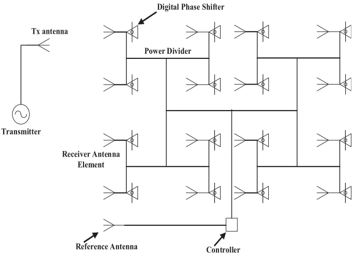
Recently, development in planar phased array antennas is equipped with electronic components varying with temperature change, drift over time, and aging effects, causing unwanted amplitude and phase errors in array elements [1–3]. Therefore, it is essential for the calibration of phased array to ascertain the amplitude and phase corrections for each element in order to attain the desired array performance. An active phased array antenna (APAA) as shown in Figure 1 consists of arrays of elements for transmitting and receiving radiation signals. The radiating elements are fed with one or more signals whose amplitude and phase determine the beam direction. The summation of the signals received with phase shifting and attenuation dictates the desired direction of the beam for each of the radiated signals [2]. Hence, to achieve maximum gain and phase for a phased array antenna, an accurate pointing of the beam of the phased array requires precise control of the amplitude and phase. Calibration is important in an active phased array antenna to compensate those amplitude and phase errors [4]. There are two categories of calibration methods, namely, single and multiple element measurement methods [1]. Researchers consider calibration techniques as an important tool in the online calibration of an active phased array antenna to establish phase and amplitude corrections for each array element in order to attain the original array performance [4]. In most single element calibration methods, antenna elements are analyzed with one by one measurement technique which are the rotating element electric field vector (REV) method proposed by Sorace [2], the phase toggling method [8], and the mutual coupling method [9]. The REV method exploits variation of the electric field when the phase shift of RF channel changes in the range of [0, 2π] [13]. Sorace’s REV method requires the output power of the measurement probe measured with one element excitation evolving all phase states. The elements are excited in four orthogonal states with the phase of each element successively shifted from 0◦ to 360◦ to determine the amplitude and phase maximum likelihood algorithm of the elements [2]. An efficient calibration
Received 5 December 2018, Accepted 13 January 2019, Scheduled 17 January 2019 * Corresponding author: Akinwale Oluwaseyi Fadamiro ([email protected]).
Tx antenna
Transmitter
Digital Phase Shifter
Receiver Antenna Element
Power Divider
Controller Reference Antenna
Figure 1. Schematic measurement configuration for the proposed 4×4 APAA calibration.
scheme using REV considers three different phase measurements at 45◦, 135◦, and 315◦ relative to the initial reference state for each element reducing the total number of measurements to perform the calibration [10].
A phase toggling method using element excitation calculates the difference value between two complex array signals measured when the phase of the element excitation is varied from 0◦ to 180◦ [8]. The geometric symmetry is very important when the measurement probe uses the antenna element next to the element being measured [9]. Multiple element measurements simultaneously calibrate a lot of elements in an array and are more efficient for large phased arrays with minimal time slot allocated to the calibration of the array antenna [1]. However, single measurement probe usually has fewer hardware facilities and simpler data processing algorithms than multiple element measurement techniques [11– 14]. Several methods have been proposed to calibrate receiver arrays at multiple element positions with planar near-field measurements and far-field radiation patterns measurement [16–26]. In [27], a complex element field is varied with every phase shift of a digital phase shifter using higher order Fourier coefficients of array power response measured with the conventional rotating element electric field vector (REV) method. The use of antennas arrays for reconfigurability and wireless sensor improves the performances of communication systems when being combined with digital back end processing unit [28–30].
The main challenge in multielement phase toggle (MEP) method is based on the number of elements calibrated in parallel, which are restricted by the bit number of the digital phase shifters. In practice, digitally controlled phase shifters are used to toggle elements phases causing amplitude and phase errors at every phase shift. These errors degrade the array performances in achieving an accurate beamforming phased arrays. Hence, it is necessary to obtain a complex element field at every phase shift and compensate for phase-to-phase variations. Therefore, numerous numerical iterations and optimizations are required to determine the corresponding element fields without an adequate guarantee that the solutions are always correct since all conventional techniques have drawbacks [27].
is organized as follows. In Section 2, theoretical principle of the proposed method is presented showing the formulas used in the antenna element excitation. In Section 3, results and discussions are provided to examine the performance of the method. Finally, some conclusions are drawn in Section 4.
2. THEORY
This proposed calibration technique characterizes the amplitude and phase of the M ×N antenna elements in a planar array using complex excitation of all elements in operation. A 2D planar array configuration is considered for all elements with proper element spacing. The receiving mode of the array is considered for the calibration of array signal measurements. Figure 1 shows a typical measurement configuration for an active phased array calibration system comprising multiple measurements with each antenna element connected to a digitally controlled phase shifter. The phase shifters are periodically modulated with the excitation of the electric field on each element and the phase shift changing from 0 to 180◦ sequentially. In this measurement process, the element electric field of theM×N planar array arranged in a rectangular grid is expressed in Equations (1) and (2).
E[m, n] =
M
m=1
Imej∅m∗ N
n=1
Inej∅n (1)
E[m, n] =
M m=1 N n=1
Imnej∅mn (2)
The electric fields errors are caused by the phase shifters (K) creating some transmitting variations different from others, where K is the maximum number of successive phase shifts set to the maximum number of phase states of the digital phase shifters. Equation (3) assumes a perfect phase and amplitude control of the element signal which is referred to as the reference state 0. The phase shifters are unlikely to give exact phase settings, hence a new phase setting is created and accompanied by a limited variation in the insertion loss. Therefore, the occurrence of the phase shifters imperfections affects the calibration process. The phase shifter errors and the quantity representing the complex signal imperfection of phase shifter are considered in Equations (4) and (5). Statistically, the smallest final error will be attained if all phase states of a digital phase shifter are utilized [6]. The electric fields measured for all phase states in each element in the array are given as
E[m, n]K = 1 K M m=1 N n=1
Imn,kej∅mn,k (3)
where E[m, n]K is the reference electric field (complex), having directly measured electric field with the successive phase shift caused by the phase shifters. The elements under calibration (EUC) ares, t, which are caused by the effect of phase shifters as given in Equations (4) and (5),
E = E[m, n]K+E[s, t]K (4)
E = 1
K M m=1 N n=1
Imn,kej∅mn,k+
1 K S s=1 T t=1
Ist,kej∅st,k (5)
array factor is expressed in matrix form as
AF[m, n] =
M
m=1 Emej
2π
λdxsinθcos∅+βx ∗
N
n=1 Enej
2π
λdysinθsin∅+βy (6)
where λis the wavelength; dx and dy are the distances between the elements along the x and y plane
axes; βx and βy are independent of each other and can be adjusted so that the main beam of E[m, x] is not the same as the E[n, y]. It is important that E[m, x] and E[n, y] intersect, and their maxima can be directed toward the same direction. The progressive shift between the elements in bothxand y directions for a planar array is given as
βx = −kdxsinθcos∅o (7)
βy = −kdysinθsin∅o (8)
wherek= 2λπ.
Hence, inserting Equation (4) in Equation (6), the derived equation can be expressed as the superposition of the planar array factor given as
F = AF[m, n]K+AF[s, t]K (9)
F = M m=1 N n=1
Emn,kej
2π
λdxsinθcos∅+βx+
S s=1 T t=1
Est,kej
2π
λdysinθsin∅+βy (10)
The second term on the right-hand side of Equations (9) and (10) representss, tarray factors generating AF scanned main beams all pointing in different directions due to the unique slope of applied phase shifters. The incremental phase shift errors, resulting from the phase shifters, are selected in such a way that there is a limited overlap. The array factor represents the contribution of the m, n not involved in the antenna array calibration, ands, t is the EUCs. The receiving antenna is placed in the far-field region of the active phased array antenna as illustrated in Figure 1. The amplitude and phase of the array are calculated with the electric field and array factor of the EUCs in Equations (5) and (10), respectively.
2.1. Calibration Method
The calibration method proposed for the active phased antenna array is solved using Euler’s numerical method on the error at receiving signals as illustrated in Figure 2, at the calibration unit. The calibration uses a feedback from the reference antenna to calibrate the error signal using a simple numerical algorithm. This feedback allows real time comparison of the calibrated signal with the reference. The phase shifters are used to toggle elements phases causing amplitude and phase errors at every phase shift as illustrated in Equations (5) and (10). The noise introduces an error vector on the right-hand side of Equations (5) and (10) on the s, t elements in the array. Euler’s numerical method is used to generate the solution to state 0 of the reference active phased array antenna as illustrated below,
yn+o = f(x) =xn (11)
yo = f(x) =xo (12)
hn = yn+o−yo (13)
yn+o = yo±h2n (14)
The complex signal tolerance is evaluated for h <= 0.01;
yn+o> yo; Subtract (15)
yn+o< yo; Add (16)
The algorithm represents the numerical method used to correct the errors withh representing error;xo
and yo represent the original signal; xn represents the error signal whileyn+o represents the corrected
Antenna Element
Beam Steering Command (θ, φ)
Calibration Unit
Reference Antenna
(A), (ϕ) (A)
Amplitude
Calculation Phase Calculation
(ϕ)
Figure 2. Schematic diagram of the active phased array calibration system.
A low tolerance error is used to evaluate the algorithm. This is to ensure that the calibrated signal has amplitude and phase as close to the reference state as possible. Furthermore, to allow critical applications where very high antenna efficiency is required, this ensures that the calibration process will be effective as the error will be minimal. The low tolerance error chosen will save resources, time and money as it would take longer time for the calibration error to vary widely than a calibration process with higher tolerance error.
2.2. Error Model for the Phase Shifters
The digital phase shifters intervals for each element on the active phased antenna array are determined independently. The phase shifts gradually increase causing errors, since an increment correlates with a bit in the digital phase shifter. The total errors obtained from the effect of the phase shifters are expressed as the increment of each bit causing errors in amplitude and phase of the EUC. A simple error model is introduced allowing for the number of known and unknown variables according to Equations (5) and (10). The number of bits could either be equal to or greater than 1 according to the numerical analysis applied. However, the unknown elements with error variations are identified along s, t in the planar array. Equation (3) assumes a perfect amplitude and phase of the active phased array antenna signal referred to as state 0. The phase shifters give an unlikely phase setting, which are compared with the signal variation. Hence, the existence of the phase shifter causes complex signal imperfection errors which affect the calibration process as described in Equations (5) and (10). The EUC, when being switched to the phase state, is repeated several times to get all elements calibrated.
3. RESULTS AND DISCUSSION
3.1. Simulation
reference state 0 for the amplitude and phase settings for each of the elements in the array.
This proposed calibration method depends on the amplitude and phase errors considered in the active phased array elements according to Equations (5) and (10) with comparison made through a feedback to the reference antenna for effective calibration. The calibration analysis evaluates three possible ways with respect to state 0 representing the perfect reference state, single, multiple and all elements calibration considerings, t as the imperfect elements in the array system.
3.2. Active Phased Array Antenna Calibration
The number of elements considered for simulation is 16, and state 0 reference state shows a perfect state for the antenna array without amplitude and phase errors as expressed in Equation (3) and illustrated in Figure 1. The element spacing used for the planar array is considered as 0.5λ. Figure 2 illustrates the algorithm used to calibrate the array system. A dynamic approach is introduced in the simulation of the array element for calibration, by evaluating state 0 reference state to the signal variation.
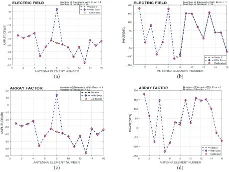
In this calibration analysis, the 16 elements uniform planar antenna array is calibrated using 5-bit phase shifters. The calibration results and errors of the amplitude and phase estimations are analyzed for comparison as shown in Figure 3–Figure 5. Hence, the accuracy of the proposed calibration method depends on the phase imperfections consider in Equations (5) and (10). This proposed calibration algorithm considers individual correction for each of the EUCs along with the phase shifts to achieve a perfect calibration.
(a) (b)
(c) (d)
3.3. Discussions
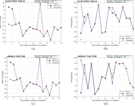
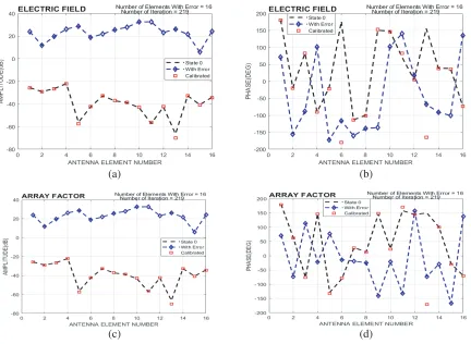
The results of the single, multiple and all elements are compared in order to validate the efficiency of the proposed calibration algorithm, shown in Figure 3–Figure 5. This analysis is based on a direct estimation of the EUCs in the array. Figure 3 shows the results of a single element calibration in an array of 16 elements. Figures 3(a)–(d) illustrate the reference state 0, the single element with error as a result of the phase shifter, and the calibration of the EUC in the electric field and array factor, respectively. The EUC has element number 8 which suffers from amplitude and phase imperfections caused by the phase shifter attached to element 8 as shown in Figure 1. The number of iterations required for correction of the error with respect to the reference state 0 is 12. Figure 4 considers 3 elements as EUCs for this calibration algorithm. The error variation of these 3 elements affects element numbers 1, 2 and 10 as a result of the phase shifters assigned to each of these elements in the array. Figures 4(a)–(d) show the calibration of the amplitude and phase of the electric field and array factor, respectively. The 3 elements considered for EUCs are calibrated within 39 iterations. Therewith, considering the entire 16 elements in the array for EUCs as shown in Figure 5, the calibration time iteration requires 219. The proposed calibration technique for single, multielement and all element calibration is illustrated in Figure 3–Figure 5, respectively. The number of iterations required to calibrate the EUCs in the active phased array element varies with the number of elements required for EUC. The results provide a comparison of the amplitudes and phases of 16 EUCs obtained from the calibration with respect to the reference state 0 at both the electric field and array factor. Hence, increase in the iteration number
(a) (b)
(c) (d)
(a) (b)
(c) (d)
Figure 5. All element (16) calibration of an active phased array antenna, (a) amplitude analysis of the electric field, (b) phase analysis of the electric, (c) amplitude analysis of the array factor, (d) phase analysis of the array factor.
creates a more accurate calibration technique relating the measurement of the signal to noise ratio experienced in the phase and amplitude deviation.
Since the calibration time increases due to the complexity of the array system, it is essential to reduce the calibration time to make the beam steering system faster. Euler’s calibration algorithm is faster, simpler and easier to integrate than previous algorithms, such as linear equation, Fast Fourier Transform, Inverse Fourier Transform, Discrete Fourier Transform and Harmonics as compared in Table 1.
Table 1. Comparison with previous work.
Approach
This work, Euler’s Method
Linear Equation
[1, 14]
Linear Equation
[3]
Higher order Fourier coefficients
[6, 15, 27]
Linear Equation
[2, 10]
Discrete Fourier transform (DFT) [13] Calibration
method Multiple Multiple Multiple Multiple Single Multiple
Calibration Type
Phase Toggle
Rotating element electric
field vector (REV)
Phase Toggle
Rotating element electric
field vector (REV)
Multi element phase-toggle
(MEP)
Phase Toggle
Complexity Simpler Complex Simpler Complex Simpler Simpler
Convergence
4. CONCLUSION
This proposed calibration technique determines a complex element electric field and array factor at every phase shift of a digital phase shifter. The entire elements of the array can be calibrated simultaneously with a larger number of iterations revolving on the phase shifters. Short calibration times are of greater advantage when the array elements consist of a larger number of radiating elements. This novel Euler’s calibration approach is designed for an active phased array antenna with a key characteristic of simultaneous calibration of all elements in a large array. The accuracy of this method is better than existing calibration methods relating the state 0 reference state to the error variation caused by the phase shifters, giving better flexibility to correct the phase shifters imperfection, enhancing the calibration accuracy of the active phased array antenna. The proposed calibration method is easily applied to an operating active phased array antenna with a significant calibration time applicable in radar, satellite and wireless communication systems.
ACKNOWLEDGMENT
The authors would like to acknowledge the support of Anhui Province Key Laboratory of simulation and design for Electronic Information System, Hefei Normal University, China; Information Science Laboratory Center of USTC for software & hardware services, MediaTek for USTC students, Micro/Nano-Electronic System Integration R&D Centre, University of Science and Technology China; and Chinese Academy of Sciences and The World Academy of Sciences (CAS-TWAS) for their financial support.
REFERENCES
1. Long, R., J. Ouyang, F. Yang, W. Han, and L. Zhou, “Multi-element phased array calibration method by solving linear equations,” IEEE Trans. on Antennas Propag., Vol. 65, No. 6, 2931– 2939, 2017.
2. Sorace, R., “Phased array calibration,”IEEE Trans. on Antennas Propag., Vol. 49, No. 4, 517–524, 2001.
3. Keizer, P. M. N., “Fast and accurate array calibration using a synthetic array approach,” IEEE Trans. on Antennas Propag., Vol. 59, No. 11, 4115–4122, 2011.
4. Miguel, S. N., M. R. O. A. Ram´on, H. A. Leandro, and S. P. Manuel, “Novel reception and transmission calibration technique for active antenna array based on phase center estimation,”
IEEE Trans. on Antennas Propag., Vol. 65, No. 10, 5511–5522, 2017.
5. Mano, S. and T. Katagi, “A method for measuring amplitude and phase of each radiating element of a phased array antenna,” Electron. Commun. Jpn., Vol. 65, No. 5, 58–64, 1982.
6. Takahashi, T., H. Miyashita, Y. Konishi, and S. Makino, “Theoretic a study on measurement accuracy of rotating element electric field vector (REV) method,”Electron. Commun. Jpn., Vol. 89, No. 1, 22–23, 2006.
7. Hu, C. N., “A novel method for calibrating deployed active antenna arrays,” IEEE Trans. on Antennas Propag., Vol. 4, No. 63, 1650–1657, 2015.
8. Lee, K. M., R. S. Chu, and S. C. Liu, “A built-in performance monitoring/fault isolation and correction (PM/FIC) system for active phased-array antennas,”IEEE Trans. on Antennas Propag., Vol. 41, No. 11, 1530–1540, 1993.
9. Aumann, H. M., A. J. Fenn, and F. G. Willwerth, “Phased array antenna calibration and pattern prediction using mutual coupling measurements,”IEEE Trans. on Antennas Propag., Vol. 37, No. 7, 844–850, 1989.
10. Zalawadia, K., P. Jain, H. Shah, and U. Dalal, “An efficient calibration scheme for satellite onboard receive digital beamformer,”IETE Journal of Research, Vol. 61, No. 6, 590–595, 2015.
12. Lier, E., M. Zemlyansky, D. Purdy, and D. Farina, “Phased array calibration and characterization based on orthogonal coding: Theory and experimental validation,”Proc. IEEE Int. Symp. Phased Array Syst. Technol., 271–278, Oct. 2010.
13. He, C., X. Liang, J. Geng, and R. Jin, “Parallel calibration method for phased array with harmonic characteristic analysis,” IEEE Trans. on Antennas Propag., Vol. 62, No. 10, 5029–5036, 2014. 14. Long, R. and J. Ou Yang, “Planar phased array calibration based on near-field measurement
system,” Progress In Electromagnetics Research C, Vol. 71, 25–31, 2017.
15. Takahashi, T., Y. Konishi, S. Makino, H. Ohmine, and H. Nakaguro, “Fast measurement technique for phased array calibration,”IEEE Trans. on Antennas Propag., Vol. 56, No. 7, 1888–1899, 2008. 16. Ng, B. C. and C. M. S. See, “Sensor-array calibration using a maximum likelihood approach,”
IEEE Trans. on Antennas Propag., Vol. 44, No. 6, 827–835, 1996.
17. Solomon, I. S. D., D. A. Gray, Y. I. Abramovich, and S. J. Anderson, “Receiver array calibration using disparate sources,”IEEE Trans. on Antennas Propag., Vol. 47, No. 3, 496–505, 1999. 18. Ng, B. P., J. P. Lie, M. H. Er, and A. Feng, “A practical simple geometry and gain/phase calibration
technique for antenna array processing,”IEEE Trans. on Antennas Propag., Vol. 57, No. 7, 1963– 1972, 2009.
19. Bucci, O. M., M. D. Migliore, G. Panariello, and P. Sgambato, “Accurate diagnosis of conformal arrays from near-field data using the matrix method,”IEEE Trans. on Antennas Propag., Vol. 53, No. 3, 1114–1120, 2005.
20. Migliore, M. D., “A compressed sensing approach for array diagnosis from a small set of near-field measurements,” IEEE Trans. on Antennas Propag., Vol. 59, No. 6, 2127–2133, 2011.
21. Long, R., J. Ouyang, F. Yang, Y. Li, K. Zhang, and L. Zhou, “Calibration method of phased array based on near-field measurement system,” Proc. IEEE Antennas Propag. Soc. Int. Symp. (APSURSI), 1161–1162, Jul. 2014.
22. Patton, W. T. and L. H. Yorinks, “Near-field alignment of phased-array antennas,” IEEE Trans. on Antennas Propag., Vol. 47, No. 3, 584–591, 1999.
23. Pawlak, H. and A. F. Jacob, “An external calibration scheme for DBF antenna arrays,” IEEE Trans. on Antennas Propag., Vol. 58, No. 1, 59–67, 2010.
24. Gupta, I. J., J. R. Baxter, S. W. Ellingson, H. G. Park, H. S. Oh, and M. G. Kyeong, “An experimental study of antenna array calibration,” IEEE Trans. on Antennas Propag., Vol. 51, No. 3, 664–667, 2003.
25. Son, S. H., S. Y. Eom, S. I. Jeon, and W. Hwang, “Automatic phase correction of phased array antennas by a genetic algorithm,” IEEE Trans. on Antennas Propag., Vol. 56, No. 8, 2751–2754, 2008.
26. Silverstein, S. D., “Application of orthogonal codes to the calibration of active phased array antennas for communication satellites,”IEEE Trans. on Antennas Propag., Vol. 45, No. 1, 206–218, 1997.
27. Takahashi, T., Y. Konishi, and I. Chiba, “A novel amplitude only measurement method to determine element fields in phased arrays,” IEEE Trans. on Antennas Propag., Vol. 60, No. 7, 3222–3230, 2012.
28. Donelli, M. and P. Febvre, “An inexpensive reconfigurable planar array for Wi-Fi applications,”
Progress In Electromagnetics Research C, Vol. 28, 71–81, 2012.
29. Viani, F., L. Lizzi, M. Donelli, D. Pregnolato, G. Oliveri, and A. Massa, “Exploitation of parasitic smart antennas in wireless sensor networks,” Journal of Electromagnetic Waves and Applications, Vol. 24, 993–1003, 2010.