Study on Temperature Sensitive Characteristics of UHF Radio
Frequency Identification Temperature Sensing Tag
Hongbin Ge*, Yuan Yao, and Junsheng Yu
Abstract—In order to design a robust passive temperature sensing tag that can operate over a wide temperature range, temperature-sensitive characteristic of UHF radio frequency identification temperature sensing chip and corresponding tags are studied. The devices under test include dipole tags with different antenna impedances. Simulation data, experiment design, system setup, measurement procedures, and test results are given. The results show that as temperature increases, the real part of chip impedance increases, and the absolute value of the imaginary part decreases, which are consistent with simulation data. In the full temperature range, the overall performance of sensing tags designed for high-temperature conditions is better than tags designed only for room temperature conditions.
1. INTRODUCTION
Passive UHF Radio frequency identification (RFID) technology is considered promising among the existing Internet of Things (IoT) solutions due to its low cost, easy maintenance, and extended operating range. Besides the conventional identification function, researchers and manufacturers have tried to add sensing functions to it, such as temperature [1], humidity [2], pressure [3], leading to an emerging research and application area.
A typical passive UHF RFID system includes tags, readers, and software, where tags are usually composed of tag antennas and chip. The tag antenna activates the chip by receiving electromagnetic waves emitted by the reader, and the minimum activation power is often called the sensitivity of the chip. Previously, the integration of sensor modules into traditional passive RFID chips was limited by power consumption, and the working distance was close. As technology evolves, the power consumption of chips and sensor modules continues to decrease, and it is no longer a constraint on integrated on-chip sensors.
Tag performance has a crucial impact on the entire system performance. In most passive RFID tag design, first, select the appropriate chip and then design the tag antenna to cooperate with it to achieve optimal tag performance.
Since the chip contains nonlinear components such as transistors and capacitors, its input impedance is power and frequency dependent. The common practice is designing the antenna impedance as the complex conjugate of the chip impedance at the sensitivity power level in order to get maximum power transfer from the tag antenna to the chip at the possible most extended reading range.
In addition to the incident power and operating frequency, the chip input impedance also relates to the environmental parameters (e.g., temperature). The environment can affect chip and tag performance, especially for sensing chips. Therefore, it is proper to incorporate the characteristics of the sensing chip into the overall tag design.
If we aim to improve the performance of temperature sensing tag under high-temperature conditions, the straightforward idea is to measure the temperature-sensing chip impedance change
Received 26 March 2019, Accepted 22 May 2019, Scheduled 31 May 2019
* Corresponding author: Hongbin Ge ([email protected]).
with temperature directly, and then design the tag antenna matching the chip according to the results. However, direct chip impedance measurement under the high-temperature condition is challenging. The final result is likely to fluctuate significantly. Measurement is easier to control and adjust at room temperature than the high-temperature condition. Accuracy cannot be guaranteed.
In this paper, we measure the overall tag performance as temperature changes, and then indirectly analyze and verify the temperature-sensitive characteristics of the chip. Design guidelines are provided for the subsequent design of robust temperature sensing tags that operate in a wide temperature range. The structure of this paper is as follows. First, the temperature-sensitive characteristics of the chip and its simulation data are described. Then, the design, setup, and procedures of the experiment are introduced, followed by the analysis and discussions of the test results. Finally, a summary and future work are presented.
2. SIMULATIONS
In this section, we will describe the temperature sensitive characteristic of a chip and its simulation data.
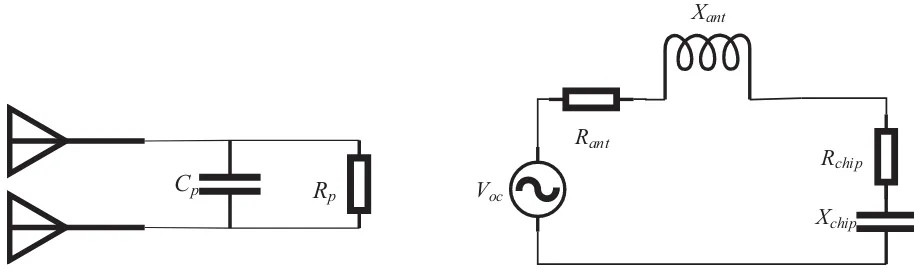
Due to the physical characteristics of the chip itself, its equivalent circuit model is usually represented as a parallel combination of resistor and capacitor [4], as shown in Figure 1. WhereRpis the equivalent parallel resistance, Cp is the equivalent parallel capacitance. However, the equivalent circuit model of the dipole antenna commonly used in the tag antenna is a series combination of resistor and inductor. In order to facilitate the analysis of the overall performance of the tag, the parallel equivalent circuit of the chip is generally converted into a corresponding series equivalent circuit model. The series equivalent circuit model of the tag is shown in Figure 2, whereVocis the open circuit voltage of the tag,
Rant and Xant are the real and imaginary parts of the tag antenna impedance, respectively, and Rchip and Xchip are the real and imaginary parts of the chip impedance, respectively.
C
pR
pFigure 1. Chip equivalent parallel circuit model.
Rant
Xant
Xchip
Rchip
Voc
Figure 2. Tag equivalent series circuit model.
For a given frequencyf =w/2π, the conversion relationship between the resistor-capacitor parallel and series equivalent circuit is
Rs= Rp
1 + (wCpRp)2; Cs =
1 + (wCpRp)2
w2C
pRp2 (1)
where Rs is the equivalent series resistance, and Cs is the equivalent series capacitance. For an equivalent series circuit, the expression of the series impedanceZs is
Zs=Rs−jωC1
s (2)
part of the chip impedance increases; if the shunt capacitance increases, the series capacitance also increases, i.e., the absolute value of the imaginary part of the chip impedance reduces.
If the antenna impedance and chip impedance are known, the power transfer coefficient τ [4] between the antenna and the chip can be calculated by Equation (3), where Zchip represents the chip impedance, and Zant represents the antenna impedance. The higher the power transfer coefficient, the better the match between the chip and the antenna. The maximum power transfer coefficient is 1 when the antenna impedance is conjugated to the chip impedance.
τ = 4RchipRant
|Zchip+ Zant|2 (3)
The temperature sensing chip used in the subsequent experiments is a passive UHF RFID temperature sensing chip (CTESIUS series LTU27 model) developed by Zhejiang JOHAR Technology Co., Ltd. The measurable temperature range of the chip is from −40◦C to 125◦C. The temperature measurement accuracy is 1◦C, while the temperature resolution is 0.13◦C.
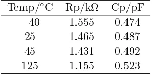
Table 1 shows the simulation data of the equivalent parallel resistance and capacitance of the chip under different temperature conditions provided by the company, as a benchmark for subsequent discussions.
It should be noted that the data listed in Table 1 are only the preliminary data. After extracting the parasitic parameters, the value ofCp needs to increase about 0.135 pF. Considering other factors such as encapsulation and glue when making tags, it is necessary to add about 0.1 to 0.2 pF. Also, the actual
Rp value may be smaller than the simulated value. The reference value of the parallel equivalent circuit
model listed in the manufacturer’s datasheet is 1.03 kΩ||0.85 pF. The simulation data show that as the temperature rises,Rp decreases andCp rises, that is, the real part of the chip impedance increases and the absolute value of the imaginary part decreases. This trend is also consistent with the relationship between the real part of the impedance and the temperature of another UHF RFID chip measured in [5]. But in [5], the imaginary part of the chip impedance is nearly unchanged with temperature because the chip has an automatic tuning function and can adjustCp within a certain range. The chip used in this paper doesn’t have this function so we can see the variation of theCp with the temperature in Table 1. Empirical formulas for the relationship between Rp, Cp and temperature T can be derived based on the simulation chip impedance data presented in Table 1.
Rp(T) = Rp0+k1rT+k2rT2 (4)
Cp(T) = Cp0+k1cT +k2cT2 (5)
where Rp0 = 1.51 kΩ is the Rp value at 0◦C; T is the temperature in ◦C; andk1r =−1.46×10⁻³ and
k2r = −1.13×10⁻⁵ are the coefficients of Rp as a function of temperature. The expression of Cp is similar, whereCp0= 0.48 pF is theCp value at 0◦C;T is the temperature in ◦C; andk1c= 2.10×10⁻⁴ and k2c= 1.02×10⁻⁶ are the coefficients of Cp as a function of temperature.
Table 2 shows the real partRs, imaginary partXs, andQof the chip series impedance corresponding to the different Rp and Cp combinations. Rp decreases, andCp rises as the temperature rises. The step of Rp is 0.1 kΩ, and the step of Cp is 0.01 pF.
In general, the bandwidth is inversely proportional to the quality factorQ, which is the ratio of the absolute value of the imaginary part of the impedance to the real part of the impedance — the lower
Table 1. Simulation data of chip impedance as a function of temperature.
Temp/◦C Rp/kΩ Cp/pF −40 1.555 0.474
25 1.465 0.487 45 1.431 0.492 125 1.155 0.523
Table 2. Chip shunt resistor and capacitor values and equivalent series impedances @922.5 MHz.
theQ value, the wider the relative operating bandwidth. The reason for choosing 922.5 MHz is that it is the center frequency of the China Radio Frequency Identification Standard 920–925 MHz band.
3. MEASUREMENTS
In this section, we will test the temperature-sensitive characteristics of the passive wireless temperature sensing tags based on the sensing chip. The purpose is to indirectly verify the chip impedance variation with temperature through the experiment and provide reference and design criteria for the design of robust temperature sensing tags in a wide temperature range.
The core device for measuring tag performance is Voyantic Tagformance, which generate commands compliant with the EPC Global Class1 Gen2 standard protocol to activate tags and measure the performance at each frequency point in a frequency band. In the subsequent measurement, the operating frequency range was the 860–960 MHz band, which covers the UHF RFID band approved by regulatory agencies in most countries and regions around the world.
Besides, the temperature range of the chip is [−40,125]◦C, and the performance of the chip is stable in the range of [−40,40]◦C according to the datasheet. So the discrete temperature 60◦C, 80◦C, 100◦C, 120◦C are selected for the convenience of measurement without losing generality meanwhile.
This test measures the temperature-sensitive characteristics of the tags using different antenna impedances by wireless means. The antenna form is the dipole antenna commonly used for tag antenna, and the classic T-match technique is used to adjust the real and imaginary parts of the antenna impedance. According to the simulation data of Table 1 and Table 2, two antennas with antenna impedances of 30 +j220 Ω and 50 +j180 Ω were selected for this test.
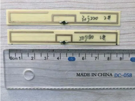
At the frequency of 922.5 MHz, the parallel combination of resistor and capacitor conjugated to the selected antenna impedances are 1.6 kΩ||0.77 pF and 0.7 kΩ||0.89 pF, respectively. The former suppose to perform better at room temperature than the latter. Theoretically, the 50 +j180 Ω antenna will be better than the 30 +j220 Ω antenna under high-temperature conditions. Subsequent measurements have verified this conjecture. Figure 3 shows the photo of the used dipole tags with 0.15 mm thick FR-4 substrate. The relative permittivity of antenna substrate material is about 4.4 at room temperature.
Figure 3. Photo of used dipole tags with different impedance.
The tag is placed 30 cm away from the reader antenna, fixed by a heat-resistant foam, and heated by a heat gun from the side. Use the Voyantic Tagformance to scan the forward reading distance of the tag. The frequency step is 0.5 MHz, and the power step is 0.1 dB. Before and after the measurement, another RFID reader is used to obtain the temperature value. When using the Voyantic Tagformance, the RFID reader must be turned off to prevent interference. At least two well-consistent tag samples were selected for both kinds of tags. For every sample, at least three tests were performed at each temperature point, and the results were averaged.
4. RESULTS
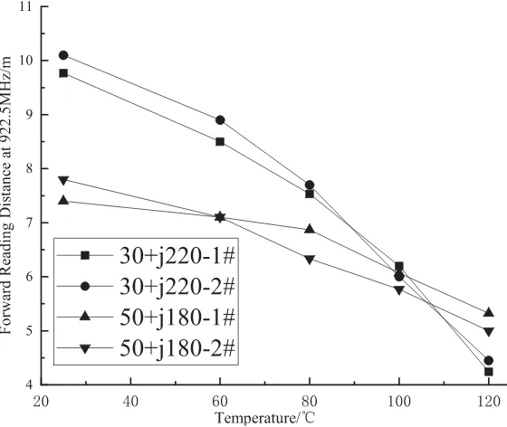
Figure 4 shows forward reading distance performances at 922.5 MHz with different temperature conditions. If the minimum reading distance over the entire wide temperature range is used as a measure of the overall performance of the tag, the tag with the antenna impedance of 50 +j180 Ω is better than the tag with the antenna impedance of 30 +j220 Ω. The 50 +j180 Ω tag antenna also has the benefit of a more comprehensive operating bandwidth due to its lower quality factor.
Figure 4. Forward reading distance of dipole tags with different impedances @922.5 MHz.
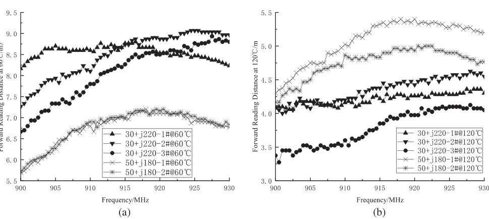
Figure 5 shows the forward reading distance for the tag antennas with two different impedances at 60◦C and 120◦C, respectively. The most representative data from the 900–930 MHz band are selected. It can be seen from Figure 5 that at 60◦C, the tag with the antenna impedance of 30 +j220 Ω performs better than the tag with the antenna impedance of 50 +j180 Ω. At 120◦C, it is the opposite. The test result is consistent with our expectation.
It is worth mentioning that the relevant tests are also carried out during the cooling process of the tag from high temperature to low temperature, and the results are consistent with the test results obtained from the heating process from low temperature to high temperature.
5. DISCUSSIONS
(a) (b)
Figure 5. Forward reading distance of dipole tags with different impedances at (a) 60◦C and (b) 120◦C.
The temperature-sensing tag designed for chip impedance under high-temperature conditions performs better than the temperature sensing tag designed only for room temperature conditions in a wide temperature range. If the temperature sensing tag is expected to work in a harsh high-temperature environment, consider designing the tag antenna as corresponding impedance, not the best impedance at room temperature.
If the evaluation criteria are the overall performance (e.g., the minimum operating distance) over the entire temperature range, it is recommended that the tag antenna is designed to be more adaptive to high-temperature conditions, even though performance at low temperature is sacrificed to some extent. However, in exchange, the overall performance of the temperature sensing tag is more stable and reliable over the entire operating temperature range.
6. CONCLUSIONS
The measured results in this paper provide reference and design ideas for the robust temperature sensing tags in the full temperature range. In future work, the method of measuring chip impedance in [6] can be improved to measure the relationship between chip impedance and temperature directly and cross-validate the results of this paper.
Alternatively, we can also explore how to accurately measure the optimal antenna impedance corresponding to the temperature change, and design the tag antenna accordingly.
Furthermore, it is possible to use a suitable temperature sensitive material as the antenna dielectric substrate, so that the antenna can adaptively adjust the antenna impedance within a certain range according to temperature changes to improve the overall performance of the temperature sensing tag.
ACKNOWLEDGMENT
The authors would like to thank Dr. Jun Yi, CTO of Zhejiang JOHAR Technology Co., Ltd., and his colleagues for their help in this project.
REFERENCES
2. Strangfeld, C., S. Johann, M. M¨uller, and M. Bartholmai, “Embedded passive RFID-based sensors for moisture monitoring in concrete,”IEEE Sensors, 1–3, 2017.
3. Fernandez, I., A. Asensio, I. Gutierrez, J. Garcia, I. Rebollo, and J. de No, “Study of the communication distance of a MEMS pressure sensor integrated in a RFID passive tag,” Advances in Electrical and Computer Engineering, Vol. 12, No. 1, 15–18, 2012.
4. Dobkin, D. M., The RF in RFID: UHF RFID in Practice, Newnes, 2012.
5. Zannas, K., H. El Matbouly, Y. Duroc, and S. Tedjini, “Self-tuning RFID tag: A new approach for temperature sensing,” IEEE Transactions on Microwave Theory and Techniques, Vol. 66, No. 12, 5885–5893, 2018.