Waveguide Integrated High-Gain Amplifier Module
for Millimeter-Wave Applications
Young Chul Lee*
Abstract—In this paper, a high-gain amplifier module has been presented for millimeter wave applications. In order to suppress oscillation of the high-gain amplification block, a rectangular waveguide (WG) is fully integrated into the metal case, on which a cascaded two-stage amplifier is mounted. Due to the integrated WG, additional microstrip line (MSL)-to-WG transitions are required. Therefore, a low-loss and wide-band WG-to-MSL transition is designed and fabricated on a 5 mil thick RT5880 substrate. Two sets of WG-to-MSL transitions in back-to-back structure are assembled in the metal case for the high-gain amplifier module and are characterized. The measured transition loss and operational return-loss (S11) bandwidth less than −10 dB are less than−0.44 dB/a transition and 15.9 GHz from 34.1 to 50 GHz, respectively. The fabricated high-gain amplifier module shows a high gain over 39.7 dB from 38 to 41 GHz. At 38.7 GHz, its maximum gain of 44.25 dB is achieved.
1. INTRODUCTION
The frequency range from 30 to 300 GHz is termed as millimeter-wave (mm-wave) frequencies, because their wavelength is between 10 to 1 mm. Because of very widely available bandwidth, several wireless communication applications such as radars [1–3], point-to-point wireless communications, radio-on- fiber (RoF) links [4], cellular wireless networks [5], etc. have migrated to mm-wave frequencies.
One of key issues for commercialization of mm-wave radios is a reproducible and cost effective packaging, aside from the active integrated circuit (IC) technology. Active IC chips are assembled on a metal or dielectric substrate carrier by using wire-bonding or flip-chip [6] interconnection and they are finally encapsulated in the plastic package or metal housing. Several materials and structures such as dielectric substrate, IC, cavity for IC mounting, waveguide (WG) are used and are integrated into the compact-volume package. Therefore, they can lead troubles such as unwanted substrate modes [6], cavity resonance [7], feedback, or crosstalk due to discontinuities [8, 9]. In the previous publications [6–9], these phenomena were well analyzed and valid models on mechanism were presented. In order to avoid them, resistivity value of the flip-chip carrier [6], resonance condition of the cavity [7], chip mounting configurations [8], and resistive coating on the lid [10] had been investigated. Various modules [1, 2, 6, 11] have been successfully implemented by reflecting these investigations. However, for the case of the high-gain amplifier block requiring higher than 30 dB, signals reflected from structural discontinuities can cause stability problem due to the feedback effects [8, 9]. The radiated signals can enter into one amplifier in the whole high-gain block by reflecting from around structures and they can be amplified. As a result, the high-gain amplifier module can be oscillated. Therefore, in order to suppress the feedback effects, a small- or medium-gain amplifier module [2, 12, 13] is cascaded in series by using external waveguides (WGs) until a required gain is satisfied or a passive component such as an attenuator and filter is
Received 11 October 2015, Accepted 11 November 2015, Scheduled 17 November 2015 * Corresponding author: Young Chul Lee ([email protected]).
5-mil thick RT5880 substrate. The simulated and tested results of the transition were presented. The high-gain amplifier module integrating a WG is fabricated and its measured performance is analyzed.
2. WAVEGUIDE INTEGRATED METAL CASE
In general, in a high-gain block or module consisting of multi-stage amplifier components, each amplifier or gain block makes spurious radiation, and it can propagate to other amplifiers or gain blocks and then it is amplified. The preventive solution for this feedback effect is isolation between two neighboring amplifiers or gain blocks. Figure 1 shows a proposed metal case inserting a 15.7 mm long WG between two cavities. This technique allows high-gain amplification without oscillation because of good isolation between two enclosed metal cavities. An amplifier IC will be assembled in each cavity. Because radiated signals can be confined to each cavity, another amplifier IC is not affected. Comparing to the conventional cascade high-gain block [2, 13] connecting external WGs or other passive components [14], the compact and low-cost module can be implemented for mm-wave system applications. In this work, the MSL-to-WG transition as well as an input and output port based on a WR22 WG has been designed and fabricated. The nominal rectangular size of the WR22 WG is 2.84×5.68 mm2. Two commercial amplifier ICs [15] are cascaded for high-gain remote antenna units (RAU) in the 40 GHz RoF system [4] requiring the gain of over 40 dB. The amplifier ICs and components for DC bias are mounted on a 5 mil thick RT5880 substrate [16]. Soldering pads for the amplifier ICs and 50 Ω microstrip lines (MSLs) as the signal line are designed on it. Because of the integrated WG, four MSL-to-WR22 WG transitions should be used. The main key issue is the design of the low-loss and wide-band transition.
Cavity for mounting an amp. IC Integrated
W/G
Figure 1. Proposed metal case integrating a waveguide between cavities to mount an amplifier IC.
3. LOW-LOSS MICROSTRIP LINE-TO-WAVEGUIDE TRANSITION
(a) (b)
Figure 2. (a) The configuration of the probe transition and (b) a transition module including two sets of MSL-to-WR22 WG transitions in back-to-back structure.
(a) (b)
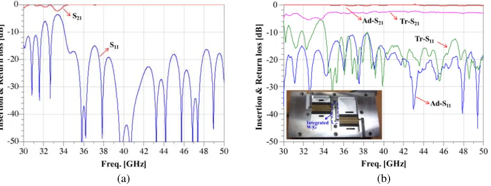
Figure 3. (a) Simulated and (b) measured results of a two-set transition in a back-to-back structure [An inset of (b): a test fixture of the fabricated MSL-to-WR22 WG transitions, Tr: transitions, and Ad: adapters].
matching line is designed for easy design and optimization. Its width and length are 295 and 1,000µm, respectively. The width of the MSL is 363µm for the 50-Ω impedance and its length between two transitions is 18.0 mm. In order to characterize its performance in a WG environment, a MSL-to-WR22 WG transition has been designed in a back-to-back structure. In order to apply it to the proposed metal case, two sets of MSL-to-WR22 WG transitions have been designed as shown in Figure 2(b). By using electromagnetic (EM) analysis software [19], MSL-to-WR22 WG transitions were simulated for low-loss and wide-band characteristics. The designed transitions were realized on the RT5880 substrate in commercial PCB foundry and the fabricated transitions were assembled on the metal case for the high-gain amplifier module.
By considering the loss components, the loss per a single transition is −0.32 and −0.44 dB at 38 and 41 GHz, respectively. Its return loss (Tr-S11) is below −10 dB from 34.1 to 50 GHz and also is similar to the simulated results. The operational bandwidth (BW) of Tr-S11for a return loss of−10 dB is also analyzed as 15.9 GHz.
4. FABRICATION OF THE HIGH-GAIN AMPLIFIER MODULE AND MEASURED PERFORMANCE
The high-gain amplifier module with an overall size of 79×42×32 mm3 was assembled in the proposed metal case. Two amplifiers are connected in series for high-gain requirement of the RoF system. Landing patterns for attachment of a SMT-type amplifier IC [15] were designed by referring to application note [20] and were realized on the RT5880 substrate. However, circuits for an input, output and inter-stage matching were not designed. In this substrate, MSL-to-WR22 WG transitions were also included in order to connect with WG.
The assembled high-gain amplifier module is presented as shown in Figure 4(a). S-parameters of the fabricated high-gain amplifier module were measured at a drain supply voltage of 5 V and total DC current of 1,000 mA and the measured results are presented in Figure 4(b), compared with characteristics plotted from a datasheet of an amplifier IC [15]. For the high-gain amplifier module, the measured gain (M-S21) more than 39.7 dB is achieved between 38 to 41 GHz. At 38.7 GHz, the maximum gain of 44.25 dB is obtained. Compared to the return losses (IC-S11 and IC-S22) of an amplifier IC, the measured input and output return loss (M-S11 and M-S22) of the high-gain amplifier module are degraded and improved, respectively, because these performances depend on assembly quality of the substrate including MSL-to-WR22 WG transitions.
In briefly, M-S21 is nearly two times of IC-S21 and M-S22 shows below −20 dB. These results demonstrate that the integrated WG provides good isolation between two amplifier ICs and suppress effectively oscillation due to feedback effects in the high-gain path.
(a) (b)
5. CONCLUSION
In this work, a high-gain amplifier module with a 40 dB gain without oscillation has been presented for millimeter wave applications. It has been demonstrated that a cascaded amplifier module can amplify the gain more than 40 dB. In order to enhance isolation between two amplifier ICs, a waveguide (WG) was fully integrated into the metal case. Due to the integrated WG, a low-loss and wide-band MSL-to-WR22 WG transition was realized on a 5 mil thick RT5880 substrate. Its measured loss and operational bandwidth were less than −0.44 dB/a transition and 15.9 GHz, respectively. The fabricated high-gain amplifier module showed a high gain over 39.7 dB from 38 to 41 GHz. Its maximum gain of 44.25 dB was obtained at 38.7 GHz. This work can contribute to the design of a small-size and low-cost high-gain amplifier module for millimeter wave applications.
ACKNOWLEDGMENT
This work was supported by Telecom Malaysia Research and Development (TMRND), Malaysia.
REFERENCES
1. Tessmann, A., S. Kudszus, T. Feltgen, M. Riessle, C. Sklarczyk, and W. H. Haydl, “A 94 GHz single-chip FMCW radar module for commercial sensor applications,”IEEE MTT-S International Microwave Symposium, Vol. 3, 1851–1854, 2002.
2. Tessmann, A., A. Leuther, M. Kuri, H. Massler, M. Riessle, H. Essen, H. Stanko, R. Sommer, M. Zink, R. Stibal, W. Reinert, and M. Schlechtweg, “220 GHz low-noise amplifier modules for radiometric imaging applications,” The 1st European Microwave Integrated Circuits Conference, 137–140, 2006.
3. Kim, J.-G., D.-W. Kang, B.-W. Min, and G. M. Rebeiz, “A single-chip 36–38 GHz 4-element transmit/receive phased-array with 5-bit amplitude and phase control,”IEEE MTT-S International Microwave Symposium, 561–564, 2009.
4. Yaakob, S., N. M. Samsuri, R. Mohamad, N. E. Farid, I. M. Azmi, S. M. M. Hassan, N. Khushairi, S. A. E. A. Rahim, A. I. A. Rahim, A. Rasmi, A. K. Zamzuri, S. M. Idrus, and S. Fan, “Live HD video transmission using 40 GHz radio over fibre downlink system,” IEEE 3rd International Conference on Photonics (ICP), 246–249, 2012.
5. Rangan, S., T. S. Rappaport, and E. Erkip, “Millimeter wave cellular wireless networks: Potentials and challenges,”Proceedings of the IEEE, Vol. 102, 366–385, 2014.
6. Tessmann, A., M. Riessle, S. Kudszus, and H. Massler, “A flip-chip packaged coplanar 94 GHz amplifier module with efficient suppression of parasitic substrate effects,” IEEE Microwave and Wireless Components Letters, Vol. 14, 145–147, 2004.
7. Dhar, J., R. K. Arora, A. Dasgupta, and S. S. Rana, “Enclosure effect on microwave power amplifier,”Progress In Electromagnetics Research C, Vol. 19, 163–177, 2011.
8. Krems, T., A. Tessmann, W. H. Haydl, C. Schmelz, and P. Heide, “Avoiding cross talk and feedback effects in packaging coplanar millimeter-wave circuits,” IEEE MTT-S International Microwave Symposium, Vol. 2, 1091–1094, 1998.
9. Beilenhoff, K. and W. Heinrich, “Excitation of the parasitic parallel-plate line mode at coplanar discontinuities,” IEEE MTT-S International Microwave Symposium, Vol. 3, 1789–1792, 1997. 10. Yook, J.-G., L. P. B. Katehi, R. N. Simons, and K. A. Shalkhauser, “Experimental and theoretical
study of parasitic leakage/resonance in a K/Ka-band MMIC package,” IEEE Transactions on Microwave Theory and Techniques, Vol. 44, 2,403–2,410, 1996.
11. Lee, Y. C., W.-I. Chang, and C. S. Park, “Monolithic LTCC SiP transmitter for 60 GHz wireless communication terminals,” IEEE MTT-S International Microwave Symposium, 1015–1018, 2005. 12. Radisic, V., X. Mei, S. Sarkozy, W. Yoshida, P.-H. Liu, J. Uyeda, R. Lai, and W. R. Deal, “A
[Online]. Available: http://www.datasheetlib.com/datasheet/168419/ammp-6441-tr2g avago-technologies.html.
16. Rogers Corporation [Online]. Available: http://www.rogerscorp.com.
17. Leong, Y.-C. and S. Weinreb, “Full band waveguide-to-microstrip probe transitions,”IEEE MTT-S International Microwave Symposium, 1435–1438, 1999.
18. Shireen, R., S. Shi, an D. W. Prather, “W-band microstrip-to-waveguide transition using via fences,”Progress In Electromagnetics Research Letters, Vol. 16, 151–160, 2010.
19. CST Microwave Studio [Online]. Available: https://www.cst.com.

![Figure 4. (a) The fabricated high-gain amplifier module and (b) its measured results, compared withamplifier IC (AMMP-6441) ones from its data sheet [M: measurement of the amplifier module and IC:data sheet of an amplifier IC].](https://thumb-us.123doks.com/thumbv2/123dok_us/7743129.1268498/4.612.102.517.500.685/fabricated-amplier-measured-compared-withamplier-measurement-amplier-amplier.webp)
