DSP BASED CASCADE SPEED CONTROL OF DC
MOTOR USING DUAL CONVERTER
Prof. Sandhya Kumar
1, Dr. Prof. Anjali Deshpande
2,
Prof. Ashish Ukidve
3, Prof. Servesh Gupta
41,4
Electronics and Telecommunication,
3Princilal,Vidyalankar Polytechnic,( India)
2Electronics Department, Vidyalankar Institute of Technology, (India)
ABSTRACT
Cascade control can provide better stability and faster control operation in the presence of disturbances and
variations in load. It has numerous applications in DC drive systems which are an integral part of renewable
energy systems based on wind source. In this paper we present, cascade control of PMDC motor using DSP
processor(DSPIC30F6012A) to control the speed of DC motor in both directions using dual converter.
Experimental results using cascade control show that the response of systemis improved as compared to the
system without current control as inner loop.Speed of Motor is tracked with an accuracy of 99.28% and better
time response with cascade controller as compared to single controller which has an accuracy of 98.42%.
Keywords: DSP, Cascade, Dual- Converter, DC Motor.
I. INTRODUCTION
Permanent magnet DC Motors and their control drives are playing very importantrole in industrial applications such
as electrical vehicles, steel rolling mills, electric crane, robotic manipulators and also for commercial applications
like home appliances, washers, driers and compressors. Apart from these, DC motors are also used in wind energy
which is most important source of renewable energy. For all the above applications, speed control of dc motor is
required with respect to change in load and disturbances[1].With the advent of power electronics, converter based
motor control systems have become popular. In [2], different Speed control techniques of DC motor have been
described along with comparative study of different converter based Speed control techniques. Cascade control
involving inner current control loop and outer speed control loop has been proved to be effective in improving the
response of control system. There is abundant literature available on cascade control, In [3] Author has proposed a
speed control strategy for thyristor driven DC Motor subjected to parameter variation.A dual mode adaptive inner
current loop is cascaded with a model referenced adaptive speed control loop. In [4] authors have presented
MATLAB aided Cascade designed controller to control and monitor DC Motor speed using microcontroller
PIC16F877A which is operated by PWM signal. In [5]Author presented a new speed control strategy of BLDCM
motor, to reduce the low precision of speed feedback of a brushless DC motor where a cascade DC-DC with
full-bridge circuit is introduced and motor closed loop speed control is achieved, In[6] Authors presented the
implementation of real time control algorithm for digital motor control.The steps required for The implementation
proposed in order to control the speed of the DC motor, In[7] Author Proposed three-level cascade structure for
robust velocity-tracking control of electrical motor drive is presented.They showed that with a cascade control
structure, adaption of controller of different motors can be easily accomplished and the robustness problems can be
solved with the most suitable technique at each control level. In[8] a novel scheme for the speed position control of
PMDC drives is presented. A cascade-control scheme,based on multiple instances of a second-order sliding mode
control algorithm is suggested,which provides accurate tracking performances under large uncertainty about the
motor and load parameters. All the above methods either demonstrate simulation results or real time
implementation using microcontrollers for unidirectional DC drives. As DSP provides easy implementation of
complex control with greater accuracy and speed of response, it is becoming popular in industrial drive systems. In
[9]a DSP based PID controller has been developed to control speed of PMDC motor. It is found to improve
accuracy of the speed control system to a great extent. To implement bidirectional speed control, Dual converter has
been used. In this paper, we have modified the existing system in [9], by implementing cascade control to
furtherimprove the system response and precision. For a permanent magnet DC motor the differential equations
describing the operation of electrical circuit are given as
( ) ( ) _________(1)
R- Armature Resistance in and L-Armature Inductance in H
( ) Armature terminal voltage
Armature back emf ( ) Armature current
a
a a a
a
a
a
di
V t Ri t L E
dt V t E i t
and for mechanical circuit are
e
( ) _____________(2)
T - Electromagnetic Torque in N-m
B-Friction Coefficient of motor and load
J-Moment of Inertial of motor and load e
d
T B t J
dt
The electrical time constant (L/R) for armature circuit is much smaller (i.e. faster) than the mechanical one
J/B.Hence we can break the system into two smaller and separated subsystems, i.e. the electrical and the
mechanical part and use two PID controllers. The changes in the load torque have a direct effect on the armature
current and hence if the current is controlled, then the transient response of the speed control system can be
improved as compared to a single PID controller. This technique is called as Cascade control. It is one of the
most popular complex control structuresimplemented to improve the disturbance rejection properties of a
controlled system. In cascade structure,each loop has associated its corresponding PID controller. The controller
of the inner loop is called secondary controller whereas controller of outer loop as the primary controller. The
structure is shown in Fig. 1.
Usually, conventional cascaded speed and current controllers are designed to ensure a definite separation of
speed and current loop in frequency domain. The separation in turn allows independent design of speed and
current controllers and minimum interaction among these loops. However there are number of practical cases,
Fig 1: Cascade Control System
In particular, when current loop is subjected to parameter variations, the conventional cascade control does not
guarantee for maintaining the outer loop in an acceptable performance [10]. To overcome this difficulty, we are
using one PID controller soft coded inside the DSP processor for speed control and other PI controller as
hardware for current control.
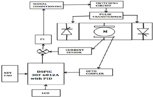
II. BLOCK DIAGRAM
The block diagram of the speed control system is as shown in Fig 2, [11]. Speed of motor is controlled below its
base speed using armature voltage control method. A Dual converter is used to provide variable voltage to the
motor in forward and reverse direction. Firing pulses for dual converter is generated using a single conditioning
unit. Optical encoder placed on the motor shaft gives real time information of speed of the motor. Current
measurement is done by Hall-effect current sensor.Hall-effect sensor produces a voltage proportional to the
measured current [12]. Output of optical encoder is compared with the voltage corresponding to preset reference
speed and the resultant error voltage is given to the PID controller.
Output of this PID controller is given to current PI controller as a set point, which is compared with the current
sensor voltage. PI controller output voltage is given to signal conditioning unit which will generate triggering
pulses for the dual converterand thus control the speed of motor.
III. HARDWARE IMPLEMENTATION
PID controller for speed is implemented using DSP.The equation for PID controller in discrete form is given
below
u
k=
u
+
K
ce
k+
K
Ie
i i=0k
å
+
K
d(
e
k-
e
k-1T
)
---(3)Where,
K
cis the Proportional gain, I ci
K
K
T
is the integral gain andK
d
K
c
T
d derivative gain and Tis Sampling time.
k
e
error at current instant
1 k
e
error at previous instantIn this project value of PID control parameters are selected by using trial and error method. The values of PID
controller parametersare given below
1
cK
sec
01
.
0
dK
sec
/
1
.
0
iK
T= 0.001sec Fsampling=1 KHzPI controller for current is implemented as shown in Fig3. Control parameters are selected as
1
2
in f pR
R
K
(From fig. 3)in c i
R
X
K
=0.03/sec whereFig 3: PI controller circuit
Motor Specifications
Motor is ¼ hp 1500rpm, 12VPMDC motor with armature current rating of 2.1amp.
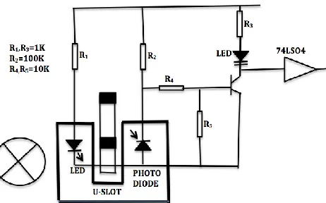
3.1 Speed Sensor
Optical encoder consists of a rotating and stationary member.The rotor is a plastic disc mounted on the motor
shaft. The disc has a kind of optical pattern that uses opaque and transparent segments which is electronically
decoded to generate position information.In this disc contains 30 strips, so encoder will generate 30 pulses in
one rotation. The stator is a module (MOC7811)consisting of an infrared emitting diode facing a photo detector
in a molded plastic housing.Output pulse of Optical encoder is converted into voltage and is given to DSP
processor.Output of DSP processor will go to PI controller as a set point.
Fig 4: Speed Sensor with Signal Conditioning
3.2 Current Sensor
Current sensor is the secondary variable of feedback used.Output of current sensor is given to PI controller as
variable input and set point of PI controller is signal generated by DSP.Current is sensed using Hall- effect
sensor ACS712. When applied current flows through this current sensor a magnetic field is produced which is
sensed by the integrated Hall IC and is converted into proportional voltage. Output of PI Controller is given to
saw tooth wave which is given to 555timer in monostable mode which produces series of pulses, which is given
to Dual Converter to trigger the SCR. The frequency of triggering pulses will change according to increase or
decrease in error voltage and accordingly firing angle will change.
Fig 5: Current Sensor with Amplifier
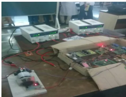
3.3 Dual Converter
Thyristors used In Dual converter is 25TT S12 with max voltage 25V.In this one converter acts as a rectifier and
other converter acts inverter. In Dual converter both the voltage and current can be reversed at dc terminal. In
this work we have used the non-circulating current control mode, which eliminates use of bulky reactor for
limiting circulating current. In this mode of operation, only one converter acts at a time. The complete hardware
implementation is given in Fig. 6.
Fig 6: Actual Implementation
IV. RESULTS
Experiments were carried out by changing the speed set-points using the keypad provided in the set-up. The
time required by the two controllers namely, single loop and cascade was observed and compared. During these
Set
Speed in
rpm
(rpm1)
Time(in sec) required to
achieve the given speed
Single
Controller
Cascade
Controller
100 20 17
200 27 24
300 34 30
400 43 39
500 52 47
600 60 53
700 67 60
800 75 67
900 84 76
1000 91 83
Table1: Response of controllers
Graph1: Response Time for Controllers
From above graph we observe that response of system with cascade control showed better performance than
system without cascade control.We also observed that at higher speed cascade system is reaching the given
speed in less time than it is for the system at lower speed.So we can observe system performance with cascade is
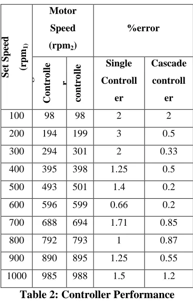
increasing at higher speed.The controller performance can be compared by calculating error as follows:
100% ] rpm2)/rpm1
-[(rpm1 =
Set Sp ee d (rpm 1) Motor Speed
(rpm2)
%error Sin g le Co ntr o lle r Ca sca de co ntr o lle r Single Controll er Cascade controll er
100 98 98 2 2
200 194 199 3 0.5
300 294 301 2 0.33
400 395 398 1.25 0.5
500 493 501 1.4 0.2
600 596 599 0.66 0.2
700 688 694 1.71 0.85
800 792 793 1 0.87
900 890 895 1.25 0.55
1000 985 988 1.5 1.2
Table 2: Controller Performance
Experimental results show that in cascade control system time required to achieve the given speed is less
compared to the time required without cascade and it has better set point tracking with an accuracy of 99.28% as
compared to single controller which has an accuracy of 98.42% as we can see in Table 2
V. CONCLUSION
The cascade speed control system is implemented for speed control of PMDC motor. Control is implemented
using DSPIC30F6012A processor and current control is implemented with separate analog control block. We
also observed that current sensor performance is better at higher speeds, possibly due to lesser effect of
disturbances. Future work includes analysis with load on a higher rated motor and also implementing circulating
current control to improve the speed of operation further.
REFERENCES
[1] Rathod Bhavina, Nitesh Jamliya, Keerti Vashishtha, (2013) “Cascade Control of a DC motor with
Advance Controller”, International Journal of Industrial Electronics and Electrical Engineering,Volume-1,
pages 18-20,ISSN:2347-6982
[2] Rohit Gupta, Ruchika Lamba, Subhransu Padhee (2012), “Thyristor based speed control techniques of dc
motor a comparative analysis”. International Journal of Scientific and Research Publication, Volume 2,
Issue 6, June 2012,ISSN :2250-3153
[3] Stephan R.M., Hahn V., Unbehauen, (1988), “Cascade adaptive Speed Control off a Thyristor driven DC
[4] Anagha, Ranjith K., Anand C P, Rahu lDas, Anusha A S(2012), “Cascade speed control of dc motor”,
International Journal of Scientific and Research Publication,Volume 2, Issue 6, ISSN:1320-2084
[5] Qingbo Hu, Zhengyu L U, Zhaoming Qian (2007), “Research on a novel Closed-loop control Technique
of brushless DC motor”, PESC2007, IEEE, pages2575-2578.
[6] Duma. R, Dobra P., Trusca M., Betea B., Sita I.V. (2012), "Embeded control of Electrical motor", ICSTC,
Pages 1-6,ISBN:978-1-4673-4534-7.
[7] Rossi C., Tonielli A.(1992)," A unifying approach to the robust control of electrical motor Drives", IEEE
conference ,vol1,Pages:95-100, ISBN:0-7803-0582-5
[8] Pisano A.,Daviala A.,Fridman L.,Usai E. (2008), "Cascade control of PMDC Drives Via Second order
Sliding-Mode Technique", IEEE journals and magazines, Volume:55, Pages:3846-3854, ISSN:0278-0046
[9] Sandhya Kumar, Anjali Deshpande (2014), “DSP based close-loop speed control system for dc motor
using dual converter.” India conference (INDICON) Annual IEEE, pages 1 – 7, ISBN:978-1-4799-5362-2
[10] P. Thrusaklhi murgan, “Robust speed controller scheme for pmbldc motor”,
www.sciencedirect.com/science/article/pu/s0019057807000717
[11] FinnHaugen, “PID Controller”,techteach.no/fag/tmpp250/v06/control/control_structures.pdf
[12] Lalit S. Patel, K.C. Dave (2011), “Cascade control technique for dc motor speed control”, In Proc of the