Simulation Comparison of Different
Dispersion Compensation Techniques in
Single Channel Optical fibre Using Optisystem
Gagandeep Kaur 1, Monika Aggarwal2
PG Student, Dept. of ECE, Bhai Gurdas Institute of Engineering &Technology, Sangrur, Punjab, India1
Associate Professor, Dept. of ECE, Bhai Gurdas Institute of Engineering &Technology, Sangrur, Punjab, India2
ABSTRACT: Advancement in Fibre Optical Technology has updated the communication sector in terms of large capacity of information transmission (video, audio, and data), high quality and cost effectiveness. The combination of photons and glass fibres provides a tremendous transmission capability improvement compared to transmission lines through electrons and copper wires. However in the C band of the optical region ranging from 1530nm-1565nm, attenuation is low but chromatic dispersion and Polarization mode dispersion puts data rate limitation in single channel network. Therefore various dispersion compensation techniques namely FBG (Fibre Bragg Grating), DCF (Dispersion compensating Fibre) and OPC (Optical Phase Conjuction) with Electroabsorption modulator and Mach-Zehnder modulator are used to compensate the dispersion so that efficient data can be transmitted through the communication medium which is typically single mode optical fibre. In this study, the performance of different dispersion compensation techniques has been studied through software OptiSystem Version 7 from Optiwave. Eye Height, BER ( Bit Error Rate) and Quality Factor (QF) have been observed to analyze the performance of these different compensation techniques to mitigate dispersion with varying bit rate from 10 Gbps to 20 Gbps and distance from 100km to 200km respectively.
KEYWORDS: Optical Fibre, Dispersion, Dispersion Compensation Techniques, Single Channel etc.
I.INTRODUCTION
Transmitting the maximum number of data bits per second over the fibre without distortion and least errors is the main objective in communication system. However, at high data rate inter-symbol interference due to dispersion causes the signal distortion, which needs to be accordingly compensated in cost effective manner. Dispersion is simply the widening of pulse duration as it travels through a fibre. As the optical pulse propagates, it gets substantially broadened to interfere with the neighbouring pulses on the optical fibre communication system, leading to Inter-Symbol Interference (ISI). Dispersion is not considered as big challenge when the bit rate was at or below 2.5 Gbps but when the distance extends to few hundred kilometers and bandwidth rose then dispersion effects the communication and needs to overcome.In long haul transmission system of over 10 Gbps speed, dispersion is major problem therefore one of the best things to speed up the optical communication networks would be to alter existing optical cables with advance cables. Hence current network has to compensate the positive dispersion of the existing single mode fibre at 1550 nm wavelength so as to make it acceptable for long distance broadband communication.Optical fibre capacity get restricted due to intensity-dependent Kerr nonlinearity limit and optical fibre channel non linear nature .So, all these limitation leads to implement different techniques to enhance the actual transmission capacity of wireless networks and optical terrestrial by implementing various compensation technique such as Fibre Bragg Grating, Uniform Fibre Bragg Grating, Ideal dispersion Compensating FBG, Optical Phase Conjuction and Dispersion Compensating Fibre.
II.DISPERSION COMPENSATION
travel with different group velocities due to the material and waveguide properties of the fibre in dispersion. Due to this all the modes reach at different times which results in “pulse broadening”. Pulse broadening depends upon distance as well as dispersion parameter. The units of dispersion parameter are ps/nm/km which varies according to fibre.
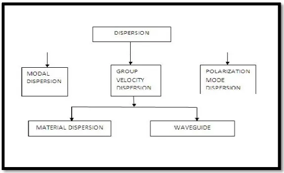
Chromatic Dispersion is the combination of material dispersion and waveguide dispersion. The classification of different types of dispersion is shown in fig.1.
Fig . 1 : Classification of different types of dispersion.
The motive of dispersion compensation is to reduce the dispersion so that transmission distance can be extended in systems operating at higher bit rate. In this paper, Dispersion Compensating Fibre Technology with diffferent modulator is used in order to reduce the dispersion caused in the system.
III.VARIOUS DISPERSION COMPENSATION TECHNIQUES
In order to increase the efficiency of the network, dispersion and other nonlinear effects should be supressed therefore, several dispersion compensation technologies were proposed as discussed below.
3.1Fibre Bragg Grating
FBG is based on the principle of Fresnel reflection, where light travelling between media having different refractive indices may refract or reflect at the interface. At a particular length the refractive index will alternate also small amount of light is reflected during refraction.These reflected light signals combine to one large reflection at a particular wavelength in which the grating period is approximately half the input lights wavelength. This is Bragg condition on the wavelength at which reflection occurs is called Bragg wavelength.The Bragg wavelength (
λβ=2
) varies along the grating length, therefore the frequency component is reflected on where the Bragg condition is satisfied. The grating dispersion= 2 (∆ )
the shorter wavelengths are delayed relative to the longer wavelengths. The chirped grating can be designed so that all wavelengths in the light pulse exit the reflector at the same time and the dispersion in the optical pulse is equalized.
3.2 Optical phase Conjucation
OPC function is to compensate chromatic dispersion and Kerr effect.The ability to compensate for Self Phase modulation through OPC was numerically calculated.Due to this ,phase distortions before conjugation that occur through Self Phase Modulation are undone by Self Phase Modulation induced phase distortions after conjugation.The prior realizations of OPC were based on stimulated Brillion scattering. Optical phase conjugation is caused with the help of device called Optical Phase Conjugator. It is used to reverse the phase propagation direction and phase of beam of light, the reversed beam is called conjugated beam. In WDM Optical system new techniques and components are being deployed to counter Four Wave Mixing effects. Methodically, it is the complex conjugate of the input power signal. In order to suppress FWM effects the optical phase conjugation is the best alternative. The Optical phase conjugator (OPC) should satisfy several requisite such as it must be transparent to signal bit-rate and modulation format, it must show a large available conjugation bandwidth, it must produce a conjugated signal with a suitable optical intensity, it must be polarization independent, and should not introduce any distortion of the signal during the OPC neither in terms of chirp nor of reduction of the optical signal to noise ratio (OSNR).
3.3 Dispersion Compensating Fibre (DCF)
The components of DCF are not easily affected by temperature and bandwidth, because DCF is more stable because they have higher negative dispersion coefficient and therefore can be connected to the transmission fibre having the positive dispersion coefficient. Therefore the overall dispersion of the link is zero.In Pre Compensation DCF is placed before the Standard Single Mode Fibre to compensate the positive dispersion of the standard fibre whereas in post Compensation DCF is placed after Standard Single Mode Fibre to compensate the positive dispersion and In Symmetrical compensation DCF is placed before as well as after Standard Single Mode Fibre (SSMF) to achieve the dispersion compensation.
Fig 2: Block diagram of Pre-compensation.
IV.PROPOSED SIMULATION MODEL
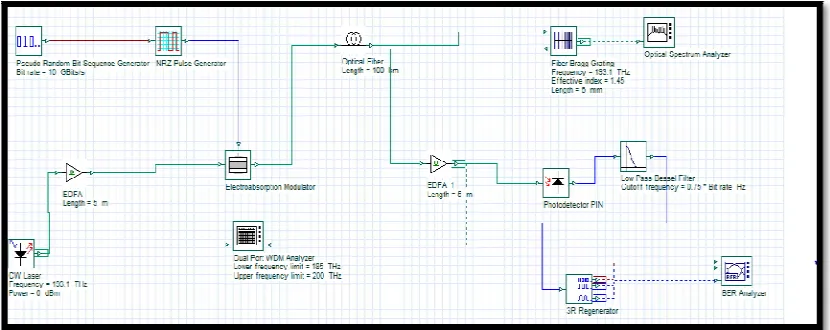
The designed system consists of block of Pseudo-Random Bit Sequence Generator (PRBS) having binary signal, sends the bit sequence to the NRZ Pulse generator.The NRZ pulse generator convert the bits into pulses and produces electrical output. The electrical output of the NRZ pulse generator is fed to the Electroabsorption Modulator. The continous wave laser emit light pulse on frequency 193.1 THz.The optical signal is then fed to Erbium doped Fibre amplifier which amplifies the light signal so it travel a long distance. In the Electroabsorption Modulator, here both the electrical and optical signal got mix and optical signal launched into optical fibre and FBG compensate the dispersion futher reduces the noise. At the receiver side, the Photo intrinsic diode(PIN) converts the optical signal into electrical signal.Low Pass Bessel Filter filters the electrical signal.The 3R regenerator consists of electrical signal as reference signal ,and binary signal and output as electrical signal also perform function of reamplification ,reshaping and retiming of data pulse .
Transmitter EDFA Single mode
fibre
EDFA
Table 1: Simulation parameters For Fibre Bragg Grating (FBG)
In uniform FBG the bandwith taken is 125 GHz .In the optical Phase conjuction and the symmetrical dispersion compensation technique the Avalanche photo diode is used.Moreover, in case of Optical Phase conjuction and pre, post and symmetrical DCF the highly non linear fibre with 0.5 km length and dispersion slope of 0.05 is considered.
Fig. 3: FBG dispersion compensation technique with Electroabsorption modulator
Parameters Values
Frequency(THz) 193.1
Power (dBm) 0
Line Width (MHz) 10
Initial Phase (deg) 0
SMF Reference waveleng(nm ) 1550
Bit Rate (Gbps) 10 -20
Length (Km) 100 -200
Attenuation (dB/Km) 0.25
Dispersion (ps/nm/Km) 5
Dispersion Slope (ps/nm/Km) 0.08
Differential Group Delay (ps/Km) 3
Apodization Function FBG Tanh
Tanh Parameter 0.5
Chirp Function Linear
Chirp Value 0.0001
Moduator Electroabsorption
Fig. 4: Optical Phase Conjuction dispersion compensation technique with Electroabsorption modulator
Fig. 5: Symmetrical dispersion compensation technique with Electroabsorption modulator
V. RESULT AND DISCUSSION
Table 2: Comparison of different dispersion compensation technique
Technique Modulator Fibre Length (Km) Bit rate (Gbps) Quality Factor (Q) Bit Error Rate (BER) Eye Height Fibre Bragg Grating Electroabsorption
100 10 38.9659 0 0.0795915
20 4.7905 7.37101 0.0257063
150
10 15.1806 1.74381 0.015215
20 3.1954 0.00067650 0.000971374
200
10 4.50815 3.00915 0.000426209
20 2.54031 0.0050172 -0.000184051
Uniform FBG
Electroabsorption
100 10 22.863 3.98519 0.0818
20 2.6828 0.00339676 -0.00966454
150 10 8.49285 6.72468 0.019405
20 2.79775 0.00235836 -0.00170955
200 10 5.51234 1.49635 0.000957247
20 2.57791 0.00432416 0.000274147
Mach-Zehnder
100 10 16.3015 4.22612 0.0828101
20 3.00285 0.00123582 8.57339
150 10 8.84657 3.52709 0.0203925
20 3.28503 0.00046107 0.00211887
200 10 6.28568 1.4955 0.00103512
20 0 1 0
Ideal dispersion compensating
fibre
Electroabsorption
100 10 10.1912 1.04185 0.0576585
20 2.9986 0.00133677 -2.67905
150
10 32.1024 1.73492 0.0228242
20 3.0193 0.001262 0.000111771
200
10 6.13974 3.62924 0.000976515
20 4.66065 1.50206 0.000583376
Mach-Zehnder
100 10 11.1085 5.4489 0.0663379
20 2.09883 0.0178804 -0.0261483
150 10 35.7336 4.43324 0.0244897
20 3.21083 0.00065848 0.00124352
200 10 6.56293 2.27497 0.00108662
20 4.44239 4.25069 0.00054171
Optical phase conjuction
Mach-Zehnder
100 10 4.45681 2.87487 5.4538
20 3.5556 0.00018822 2.13616
150 10 5.00505 2.09904 2.63165
20 1.83246 0.0306518 -2.52467
200 10 4.10655 1.87253 0.368221
From table 2 it is clear that in Fibre Bragg Grating at 100 km, 10Gbps the Q factor found is 38.9659 and BER is 0.In uniform Fibre Bragg Grating with electroabsorption modulator at 100km, 10Gbps Q factor is 22.863 and BER is 3.98519. In ideal dispersion compensating FBG with electroabsorption modulator with Mach-Zehnder modulator at 150km, 10Gbps the Q factor found is 35.7336 and BER is 4.43324. In Optical phase conjuction with Mach-Zehnder modulator at 150km at 10Gbps the Q factor found is 5.00505 and BER found is 2.09904. In post Dispersion Compensation Fibre at 10 Gbps having 100km length the Q factor is 20.0159 and BER is 1.7225. In uniform Fibre Bragg grating at 200km, 20Gbps the BER is 0. In Post DCF at 150 km, 20Gbps Q factor found is 0.At 200 km at 10Gbps and 20Gbps the results found are 0.
VI.CONCLUSION
From the results it is concluded that FBG, Uniform Fibre Bragg Grating technique and Dispersion Compensating Fibre techniques with Electro absorption gives better results than Mach-Zehnder. Dispersion Compensating Fibre techniques contains three type namely Pre dispersion compensating fibre (Pre DCF), Post Dispersion Compensating Fibre (Post DCF) and Symmetrical Compensating Fibre and among them Symmetrical DCF is best when implemented with Electroabsorption. Optical Phase Conjuction technique shows less dispersion when Machzender Modulator is used with Avalanche Photo diode instead of Photo Intrinsic diode.However, as the length and Bit rate 20Gbps increases Mach-Zehnder gives better results.In, Ideal dispersion Compensating FBG at 150km and 20Gbps Mach-Mach-Zehnder is best.
Technique Modulator
Fibre
Length
(Km)
Bit
rate
(Gbps)
Quality
Factor
(Q)
Bit
Error
Rate
(BER)
Eye Height
Pre DCF Electroabsorption100 10 19.0807 1.70088 0.201869
20 2.58358 0.004315 -0.00372272
150
10 12.2453 8.73214 0.00108851
20 2.29977 0.008986 -0.00038273
200
10 5.76947 3.76124 4.29424
20 2.31686 0.00825 -2.04567
Post DCF
Electroabsorption
100 10 20.0159 1.7225 0.0204646
20 6.02136 8.61228 0.00989347
150 10 2.61989 0.004292 -0.000200912
20 0 1 0
200 10 0 1 0
20 0 1 0
Symmetrical DCF
Electroabsorption
200 10 10.0716 3.51244 1.3711
20 2.5281 0.004746 -0.327246
300 10 2.64035 0.003921 -.000777516
20 3.20127 0.000394 0.000598704
400 10 0 1 0
REFERENCES
[1] Parul Singh and Rekha Chahar,”Performance analysis of dispersion compensation in optical fibre using DCF” The International Journal of
Engineering and Sciences, Vol.3, no.8 , pp. 18-22, 2014.
[2] Prachi Sharma et al, “A Review of the Development in the Field of Fibre Optic Communication Systems”, International Journal of Emerging
Technology and Advanced Engineering, Vol. 3, no. 5, pp. 113-119, 2013
[3] Nidhiya Shan and Asha A S, ”Simulation and analysis of Optical WDM System Using FBG as Dispersion Compensator ,” International
Journal of Engineering Research and General Science, Vol. 3,no. 2, pp. 1073-1080 , 2015.
[4] Kaushal Kumar, A.K.Jaiswal, Mukesh Kumar and Nilesh Agrawal, “Performance analysis of dispersion compensation using Fibre Bragg
Grating (FBG) in optical communication”, International journal of current engineering and technology, Vol.4, no.3, pp.1527-1531, 2014.
[5] B.Prasad, B.Mallick and A.K.Parida,” Fibre Bragg Grating as a dispersion compensator in an optical transmission system using optisystem
software”, International Research Journal of Engineering and Technology (IRJET) Vol. 2 , no.6 , pp. 9-14,2014.
[6] S. O. Mohammadi, Saeed Mozzaffari and M. Mahdi Shahidi, “Simulation of a transmission system to compensate dispersion in an optical
fibre by chirp gratings.” International Journal of the Physical Sciences, Vol. 6(32), pp. 7354 - 7360, December, 2011.
[7] K. O. Hill, F. Bilodeau, B. Malo, T. Kitagawa, S. Th´eriault, C. Johnson, J. Albert, and K. Takiguchi, “Aperiodic in-fibre Bragg gratings for
optical fibre dispersion compensation,” in Conf. Optic. Fibre Commun., OFC’94, San Jose, CA,1994.
[8] J. Harish D.Dilip Kumar and G. Aarthi, “Designing a Chromatic dispersion compensator performance comparison between NRZ and RZ”,
International Journal of Combined Research & Development (IJCRD) Vol 4,no. 5,pp. 838 -843 ,2015.
[9] Aashima Bhardwaj and Gaurav Soni,”Performance analysis of 20Gbps optical transmission system using Fibre Bragg Grating International
Journal of Scientific and Research Publications. Vol. 5, no 1, pp 1-4 , 2015 .
[10] R K Sethi, Aditya Goel “Performance Analysis of Optical Communication System using OFDM by Employing QPSK Modulation”,
International Journal on Recent and Innovation Trends in Computing and Communication (IJRITCC), vol 3, issue 1, pp.226-237 , 2015.
[11] M.A. Othman, M.M. Ismail, H.A. Sulaiman, M.H. Misran,M.A. Meor Said, Y.A. Rahim, A.N. Che Pee, M.R. Motsidi ,“An Analysis of 10