Scholarship@Western
Scholarship@Western
Electronic Thesis and Dissertation Repository
4-30-2015 12:00 AM
Power Management Strategies for a Wind Energy Source in an
Power Management Strategies for a Wind Energy Source in an
Isolated Microgrid and Grid Connected System
Isolated Microgrid and Grid Connected System
Devbratta Thakur
The University of Western Ontario
Supervisor Dr. Jin Jiang
The University of Western Ontario
Graduate Program in Electrical and Computer Engineering
A thesis submitted in partial fulfillment of the requirements for the degree in Doctor of Philosophy
© Devbratta Thakur 2015
Follow this and additional works at: https://ir.lib.uwo.ca/etd Part of the Power and Energy Commons
Recommended Citation Recommended Citation
Thakur, Devbratta, "Power Management Strategies for a Wind Energy Source in an Isolated Microgrid and Grid Connected System" (2015). Electronic Thesis and Dissertation Repository. 2839.
https://ir.lib.uwo.ca/etd/2839
This Dissertation/Thesis is brought to you for free and open access by Scholarship@Western. It has been accepted for inclusion in Electronic Thesis and Dissertation Repository by an authorized administrator of
SOURCE IN AN ISOLATED MICROGRID AND GRID CONNECTED
SYSTEM
(Thesis format: Monograph)
by
Devbratta Thakur
Graduate Program in Electrical and Computer Engineering
A thesis submitted in partial fulfillment of the requirements for the degree of
Doctor of Philosophy
The School of Graduate and Postdoctoral Studies The University of Western Ontario
London, Ontario, Canada
ii
Abstract
This thesis focuses on the development of power management control strategies for a direct drive permanent magnet synchronous generator (PMSG) based variable speed wind turbine (VSWT). Two modes of operation have been considered: (1) isolated/islanded mode, and (2) grid-connected mode.
In the isolated/islanded mode, the system requires additional energy sources and sinks to counterbalance the intermittent nature of the wind. Thus, battery energy storage and photovoltaic (PV) systems have been integrated with the wind turbine to form a microgrid with hybrid energy sources. For the wind/battery hybrid system, several energy management and control issues have been addressed, such as DC link voltage stability, imbalanced power flow, and constraints of the battery state of charge (SOC). To ensure the integrity of the microgrid, and to increase its flexibility, dump loads and an emergency back-up AC source (can be a diesel generator set) have been used to protect the system against the excessive power production from the wind and PV systems, as well as the intermittent nature of wind source. A coordinated control strategy is proposed for the dump loads and back up AC source.
An alternative control strategy is also proposed for a hybrid wind/battery system by eliminating the dedicated battery converter and the dump loads. To protect the battery against overcharging, an integrated control strategy is proposed. In addition, the dual vector voltage control (DVVC) is also developed to tackle the issues associated with unbalanced AC loads.
To improve the performance of a DC microgrid consisting wind, battery, and PV, a distributed control strategy using DC link voltage (DLV) based control law is developed. This strategy provides simpler structure, less frequent mode transitions, and effective coordination among different sources without relying on real-time communication.
iii
The proposed strategy consists of: (i) a vector current control with a feed-forward of the negative-sequence voltage (VCCF) to compensate for the negative sequence currents; and (ii) a power compensation factor (PCF) control for the VCCF to maintain the balanced power flow between the system and the grid. A sliding mode control strategy has also been developed to enhance the overall system performance. Appropriate grid code has been considered in this case.
All the developed control strategies have been validated via extensive computer simulation with realistic system parameters. Furthermore, to valid developed control strategies in a realistic environment in real-time, a microgrid has been constructed using physical components: a wind turbine simulator (WTS), power electronic converters, simulated grid, sensors, real-time controllers and protection devices. All the control strategies developed in this system have been validated experimentally on this facility.
In conclusion, several power management strategies and real-time control issues have been investigated for direct drive permanent magnet synchronous generator (PMSG) based variable speed wind turbine system in an islanded and grid-connected mode. For the islanded mode, the focuses have been on microgrid control. While for the grid-connected mode, main consideration has been on the mitigation of voltage sags at the point of common coupling (PCC).
Keywords
iv
Dedication
v
Acknowledgments
I would like to express my deep and sincere gratitude to my supervisor Prof. Jin Jiang for his excellent supervision, invaluable guidance, and immense support for the completion of this thesis.
I would like to acknowledge the University of Western Ontario, the Natural Sciences and Engineering Research Council of Canada (NSERC) and the Ontario Centre of Excellence (OCE) for supporting the research
I am highly grateful to Dr. Rajiv K. Varma, Dr. Gerry Moschopoulos, and Dr. Amirnaser Yazdani for their valuable courses and projects, which provided immense help in my research work.
I would like to thank Dr. Xinhong Huang, the research engineer with the Distributed Generation Laboratory at UWO, for her useful help in ordering parts and managing administrative work to build the experimental setup. In addition, her suggestions for thesis planning were highly appreciable.
I would also like to thank my colleagues, PhD candidate Mr. Andrew T. Moore, for providing the documents, and references for the existing inverter and the sensors in the laboratory. In addition, his experience in building physical systems was very helpful in planning my experimental setup.
I am also thankful to the group members at UWO: Elizabeth Tomaszewski, Dennis Michaelson, Hisham Mahmood, Drew J. Rankin, and Syed A. Raza for their valuable discussions and companionship.
vi
Table of Contents
Abstract ... ii
Dedication ... iv
Acknowledgments... v
Table of Contents ... vi
List of Tables ... xiv
List of Figures ... xv
Abbreviations ... xxiii
Nomenclature ... xxv
Chapter 1 ... 1
1 Introduction ... 1
1.1 General Introduction and Benefits ... 1
1.2 Motivations ... 5
1.3 Problem Statement ... 7
1.4 Objectives of the Research ... 14
1.5 Scope of the Research ... 16
1.6 Contributions of the Thesis ... 17
1.7 Literature Review... 19
1.7.1 Wind Turbine Simulator ... 20
1.7.2 Hybrid System ... 24
1.7.3 DC Microgrid ... 25
1.7.4 Grid Connected Wind System ... 27
1.8 Organization of the Thesis ... 30
Chapter 2 ... 33
vii
2.1 Wind Energy Source ... 33
2.1.1 Wind Power Production ... 34
2.1.2 Wind Energy Conversion System ... 36
2.1.3 Wind Turbine Model... 39
2.1.4 Permanent Magnet Synchronous Generator (PMSG) ... 40
2.2 Photovoltaic (PV) Energy Source ... 43
2.3 Battery Energy Storage ... 45
2.4 Structure and Control of Renewable Energy based Power System ... 47
2.4.1 Standalone System ... 47
2.4.2 Hybrid System ... 48
2.4.3 Microgrid ... 50
2.5 Conclusions ... 53
Chapter 3 ... 55
3 Design and Development of Physical Systems: Experimental Set Up ... 55
3.1 Wind Turbine Simulator (WTS) ... 55
3.1.1 Introduction ... 55
3.1.2 Structure and Design of the WTS ... 58
3.1.3 Modeling and Controller Design ... 60
3.1.4 Integration of WTS in a Microgrid ... 66
3.1.5 Experimental Validation ... 68
3.1.6 Conclusions ... 73
3.2 Commercial PV Simulator and Lead Acid Battery ... 73
3.2.1 PV Simulator ... 74
3.2.2 Lead Acid Battery ... 74
3.3 DC-DC Converter ... 76
viii
3.3.2 Design and Development of Buck Converter ... 79
3.4 DC-AC Converter (Inverter) ... 87
3.5 Real Time Controller Platforms ... 88
3.5.1 National Instrument (NI) LabVIEW ... 88
3.5.2 Texas Instrument (TI) Microcontroller ... 90
3.5.3 dSPACE ... 92
3.6 Sensors for Converters ... 94
3.7 Conclusions ... 95
Chapter 4 ... 96
4 Validation of the System Models ... 96
4.1 Permanent Magnet Synchronous Generator ... 96
4.1.1 Static Characteristics ... 97
4.1.2 Dynamic Characteristics ... 100
4.2 Photovoltaic (PV)... 103
4.3 Lead Acid Battery ... 107
4.4 Conclusions ... 113
Chapter 5 ... 114
5 Control Strategy for an Islanded Wind/Battery Hybrid System: with a Battery Converter ... 114
5.1 Introduction ... 114
5.2 Problem Statement ... 115
5.3 Conventional Structure and Control Objectives ... 116
5.4 Modeling of the System Components ... 118
5.5 Proposed Control Strategy ... 118
5.6 Simulation Studies and Discussions ... 122
ix
5.6.2 Variable Load Demand ... 126
5.7 Conclusions ... 128
Chapter 6 ... 129
6 Control Strategy for an Islanded Wind/Battery Hybrid System: without a Battery Converter ... 129
6.1 Introduction ... 129
6.2 Problem Statement ... 130
6.3 Structure of the Hybrid System... 131
6.4 Issues and Functions of the Hybrid System ... 132
6.5 Control Objectives and Strategy ... 134
6.5.1 Wind System ... 134
6.5.2 Battery System ... 136
6.6 Integrated Control Strategy (DC link) ... 137
6.6.1 Operating Strategy at DC link... 137
6.6.2 Control Strategy Selection Signal ... 138
6.7 Dual Vector Voltage Control Strategy (AC link) ... 140
6.7.1 Sequence Decomposition ... 141
6.7.2 Sequence Transformation ... 141
6.7.3 Voltage Loop ... 141
6.7.4 Current Loop ... 142
6.7.5 Sequence Composition... 143
6.7.6 Proportional-Integral (PI) Controller ... 144
6.8 Experimental Validation ... 144
6.8.1 Case Study I: System Start-Up Procedure ... 145
6.8.2 Case Study II: Charging Mode ... 146
x
6.8.4 Case Study IV: Power Curtailment ... 149
6.8.5 Case Study V: Unbalanced Voltage ... 151
6.9 Conclusions ... 153
Chapter 7 ... 154
7 Control Strategy for an Islanded Wind/PV/Battery- DC Microgrid: without a Battery Converter ... 154
7.1 Introduction ... 154
7.2 Problem Statement ... 155
7.3 Microgrid Configuration and Proposed Control Structure ... 157
7.3.1 DC Microgrid Configuration ... 157
7.3.2 Proposed Control Structure ... 158
7.4 Control and Operational Strategy ... 159
7.4.1 Control Law ... 159
7.4.2 Determination of Voltage Threshold ... 161
7.4.3 Operational Strategy ... 161
7.4.4 Smooth Operation of the Microgrid ... 162
7.5 Implementation of the Control Strategy ... 164
7.5.1 Maximum Power Point (MPP) Scheme ... 164
7.5.2 Voltage Regulation Operating (VRO) Scheme ... 165
7.6 Controller Design and Stability Analysis ... 167
7.6.1 Controller Design ... 167
7.6.2 Effect of Line Resistance and Stability Analysis ... 169
7.7 Simulation Studies ... 170
7.7.1 Case Study I: Load Shedding Scenario ... 170
7.7.2 Case Study II: Droop Control in VRO Mode ... 171
xi
7.8.1 Case Study I: Normal Operation (MPP Scheme) ... 173
7.8.2 Case Study II: Power Curtailment (VRO Scheme) ... 175
7.9 Discussions ... 177
7.10Conclusions ... 178
Chapter 8 ... 179
8 Control Strategy for a Grid Connected Wind System ... 179
8.1 Introduction ... 179
8.2 Problem Statement ... 181
8.3 System Description and Proposed Control Objectives ... 182
8.3.1 System Description ... 182
8.3.2 Control Objectives ... 183
8.4 Control System Design and Implementation ... 184
8.4.1 DC-DC Converter ... 184
8.4.2 Inverter ... 185
8.5 Simulation Studies ... 192
8.5.1 Case Study I: Without Proposed Control ... 192
8.5.2 Case Study II: Analysis of Wind System Output Current ... 193
8.6 Experimental Validation ... 194
8.6.1 Case Study I: Unbalanced Voltage Sag (13%, 63%, 50%) ... 195
8.6.2 Case Study II: Balanced Voltage Sag (46%, 46%, 46%) ... 196
8.7 Conclusions ... 198
Chapter 9 ... 199
9 Control Strategy for a Grid Connected Wind System based on Sliding Mode Control Approach ... 199
9.1 Introduction ... 199
xii
9.3 System Description ... 202
9.4 Proposed Sliding Mode Control Based Control Strategy ... 202
9.4.1 GSC: DC Link Voltage Regulation ... 203
9.4.2 NSC: Power Injection strategy... 205
9.4.3 NSC: Negative Sequence Current Regulation ... 206
9.4.4 NSC: Overall Control Strategy ... 210
9.5 Simulation Studies ... 211
9.5.1 Case Study I: Fluctuating Wind Speed ... 211
9.5.2 Case Study II: Varying System Frequency ... 212
9.5.3 Case study III: Unbalanced Grid Voltage Sag (13%, 63% and 50 %) without Compensation ... 213
9.5.4 Case study IV: Unbalanced Grid Voltage Sag (13%, 63% and 50 %) with Compensation ... 215
9.6 Experimental Validation ... 216
9.6.1 Unbalanced Grid Voltage Sag (13%, 63% and 50 %) with Compensation (SMC based control strategy) ... 216
9.7 Conclusions ... 218
Chapter 10 ... 219
10Conclusions and Future Work ... 219
10.1General Conclusion ... 219
10.2Future Work ... 223
Bibliography ... 226
Appendix A ... 246
A.1 Induction Motor Parameters (WTS) ... 246
A.2 Permanent Magnet Synchronous Generator (PMSG) Parameters ... 246
A.3 Hybrid Wind/Battery System Parameters ... 246
xiii
Appendix B ... 248
B.1 Major Components for Converter and Roof Wind Turbine Development... 248
Appendix C ... 250
C.1 Algorithm for Optimal Location and Size for a Wind Source ... 250
xiv
List of Tables
Table 1.1: Existing wind turbine simulators ... 23
Table 2.1: Aerodynamic constants of a considered wind turbine ... 35
Table 3.1:Design specifications of the WTS ... 59
Table 5.1: Control strategy for different elements in a DC microgrid ... 120
Table 6.1: Operating mode of the hybrid system (0: open, 1: close) ... 133
Table 6.2: Control strategy selection signal ... 139
Table 8.1: Critical modes for inner current and outer voltage loop ... 185
xv
List of Figures
Figure 1.1: Ontario long term energy plan [5] ... 2
Figure 1.2: Scope of the thesis using tree diagram ... 16
Figure 2.1: Type I wind system configuration ... 37
Figure 2.2: Type II wind system configuration ... 37
Figure 2.3: Type III wind system configuration ... 38
Figure 2.4: Type IV wind system configuration ... 39
Figure 2.5: Per phase model of PMSG ... 40
Figure 2.6: Stator and equivalent windings [116] ... 42
Figure 2.7: Circuit model for a PV cell... 44
Figure 2.8: A typical RES in a grid connected mode ... 48
Figure 2.9: A typical RES based hybrid system ... 49
Figure 2.10: A typical DC microgrid system ... 51
Figure 2.11: A typical AC microgrid system ... 52
Figure 3.1: An experimental microgrid ... 57
Figure 3.2: Proposed structure of the WTS ... 58
Figure 3.3: Power coefficient curve of the actual wind turbine ... 60
Figure 3.4: Representation of turbine dynamics using (a) PWT and (b) M-G set ... 61
Figure 3.5: Block diagram of WTS with the compensated torque ... 62
xvi
Figure 3.7: Configuration of the flux observer ... 66
Figure 3.8: Physical system based laboratory scale microgrid ... 67
Figure 3.9: Comparison of (a) Power curve and (b) Cp- TSR curve between the WTS and a PWT ... 68
Figure 3.10: Comparison of WTS and PWT output power, rotor speed, torque and their errors at the measured wind speed: (I) instantaneous wind profile and (II) average wind profile .... 70
Figure 3.11: Activation of pitch angle control ... 71
Figure 3.12: Performance of the WTS within a microgrid environment ... 72
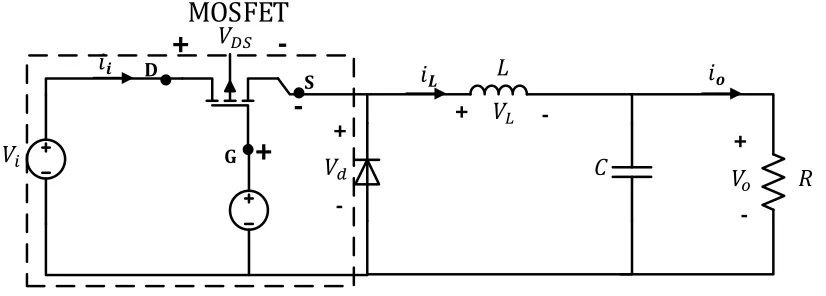
Figure 3.13: Buck converter topology ... 76
Figure 3.14: Topological mode I: Switch ON period ... 77
Figure 3.15: Topological mode I: Switch OFF period ... 77
Figure 3.16: Inductor voltage and current waveforms ... 78
Figure 3.17: Buck converter based on N-channel MOSFET ... 85
Figure 3.18: Isolated gate drive circuit ... 86
Figure 3.19: Block diagram of WTS... 89
Figure 3.20: Front panel for WTS... 89
Figure 3.21: I/O Module of NI with Chassis ... 90
Figure 3.22: Real time control of DC-DC converter in a microgrid using TI C2000... 91
Figure 3.23: Real time control of inverter using dSPACE ... 93
Figure 3.24: Inverter user interface developed using dSPACE control desk ... 93
xvii
Figure 3.26: Printed circuit board diagram for DC voltage and current sensors ... 94
Figure 4.1: Experimental set up for PMSG ... 96
Figure 4.2: AC voltage (rms) vs AC current (rms) during experiment and simulation ... 98
Figure 4.3: DC voltage vs DC current from experiment and simulation ... 100
Figure 4.4: Simulation results of PMSG under variable rpm ... 101
Figure 4.5: Experimental results of PMSG under variable rpm ... 102
Figure 4.6: Experimental configuration for PV source ... 104
Figure 4.7: I-V characteristics of PV module from simulation and experiment ... 105
Figure 4.8: P-V characteristics of PV module from simulation and experiment ... 106
Figure 4.9: CIEMAT model results from [125] ... 108
Figure 4.10: CIEMAT model results ... 109
Figure 4.11: Experimental configuration for lead acid battery ... 110
Figure 4.12: Simulation results of lead acid battery ... 111
Figure 4.13: Experimental results of lead acid battery ... 112
Figure 5.1: Hybrid system with a conventional structure in a DC microgrid ... 114
Figure 5.2: PMSG wind turbine based DC microgrid ... 117
Figure 5.3: DC link voltage control strategy ... 119
Figure 5.4: (a) Battery converter control strategy, and (b) AC source activation signal ... 120
Figure 5.5: (a) Dump load control, and (b) AC source based DC link voltage control ... 121
xviii
Figure 5.7: Zoom version of DC link voltage during transient (a) at 2s, (b) at 4s, (c) at 6s, and
(d) at 10s ... 123
Figure 5.8: Direct current (DC) under changing wind speed: (a) DC load, (b) wind, (c) dump load, (d) battery, and (e) AC source current ... 124
Figure 5.9: (a) SOC, (b) Wind switching status, (c) AC source switching status, and (d) Dump load switching status ... 126
Figure 5.10: DC output under varying load demand: (a) DCL voltage and current, (b) Wind current, (c) Dump load current, and (d) Battery current ... 126
Figure 5.11: AC link output during variable load: (a) AC voltage (ACV), and (b) AC current (ACC) ... 127
Figure 6.1: Schematic diagram of the hybrid-wind and battery system ... 131
Figure 6.2: Hybrid system in a microgrid ... 133
Figure 6.3: MPPT scheme for a wind system ... 135
Figure 6.4: Pitch angle control scheme ... 135
Figure 6.5: Block diagram of DC link voltage control ... 136
Figure 6.6: Power management scheme using integrated control strategy ... 137
Figure 6.7: Dual vector voltage control strategy for unbalanced AC link voltage ... 140
Figure 6.8: Experimental configuration of the hybrid system ... 145
Figure 6.9: Black start capability of hybrid system (a) DC link voltage (b) Load current (c) Battery current (d) Wind current (e) Power coefficient and (f) Battery’s state of charge .... 146
xix
Figure 6.11: Battery discharging mode of operation in hybrid system (a) DC link voltage (b) Load current (c) Battery current (d) Wind speed (e) Wind current (f) Power coefficient and
tip speed ratio and (g) Battery’s state of charge ... 149
Figure 6.12: Power curtailment in hybrid system (a) DC link voltage (b) Load current (c) Battery current (d) Wind current (e) Power coefficient (f) Wind turbine rotor speed (g) Pitch angle and (h) Battery’s state of charge ... 150
Figure 6.13: AC link of hybrid system under unbalanced load (a) AC link voltage (b) AC 152 Figure 6.14: AC link of hybrid system under unbalanced load with proposed technique: (a) AC link voltage (b) AC link current (c) AC link frequency ... 152
Figure 7.1: Schematic diagram of a studied islanded microgrid ... 157
Figure 7.2: Block diagram of the proposed control structure for a DC microgrid ... 159
Figure 7.3: Control law for a DC microgrid ... 160
Figure 7.4: Control law for a DC microgrid ... 163
Figure 7.5: MPP scheme for: (a) Wind (b) PV ... 164
Figure 7.6: Control block diagram for voltage threshold based VRO ... 165
Figure 7.7: Control block diagram for droop control based VRO ... 166
Figure 7.8: Control block diagram of buck converter... 167
Figure 7.9: Modes trajectories in an s-plane (a) inner current loop (b) outer voltage loop .. 168
Figure 7.10: Modes trajectories in an s-plane due to line resistance ... 169
Figure 7.11:Microgrid operation including load shedding (a) DC link voltage (b) Load shedding signal and (c) Current flow (sources, storage and load) ... 170
xx
Figure 7.13: Experimental setup for DC microgrid ... 173
Figure 7.14: Microgrid normal operation (a) DC link voltage (b) Load current (c) Battery current (d) Wind speed (e) Wind current (f) Rotor speed and (g) PV current ... 174
Figure 7.15: Microgrid operation during extreme condition: (a) DC link voltage (b) Resistive load (c) Battery current (d) Wind speed (e) Wind current (f) Power coefficient (Cp) and normalized tip speed ratio (TSR) and (g) PV current ... 176
Figure 8.1: Schematic diagram of PMSG based WPS connected to grid ... 183
Figure 8.2: Control block diagram of DC link voltage control... 184
Figure 8.3: MPPT scheme with PCF control ... 187
Figure 8.4: Characteristics curve of a wind turbine for same wind speed at different pitch angle ... 188
Figure 8.5: Vector current control in positive SRF under VCCF scheme ... 191
Figure 8.6: Performance of the wind system under an unbalanced three phase grid voltage sag without control (Zoomed waveform before and after the fault is shown just below each waveform): (a) Grid AC voltage at PCC (b) Positive-sequence axes voltage (c) Reference and positive-sequence components of current (d) Negative-sequence components of current (e) PLL-Omega (rad/s) and -axis voltage and (f) DLV ... 193
Figure 8.7: Performance of the wind system under an unbalanced three phase grid voltage sag: (a) Output currents without VCCF and PCF (b) Output currents with VCCF only (c) Output currents with both VCCF and PCF and (d) Zoomed version of (c). ... 194
Figure 8.8: Experimental setup in the laboratory... 195
xxi
Figure 8.10: Performance of the wind system under an balanced three phase grid voltage sag with the proposed control: (a) Grid AC voltage (b) Turbine power (c) Turbine torque (d) Rotational speed (e) Power coefficient (f) DLV (g) Positive-sequence components of voltage (h) Positive-and negative- sequence components of the current (i) PLL-Omega and axis voltage and (j) Active and reactive power ... 197
Figure 9.1: Schematic diagram of PMSG based VSWT in Power Grid Network ... 202
Figure 9.2: Control block diagram for VCCF ... 207
Figure 9.3: Block diagram of the simplified SMC for inverter voltage output ... 210
Figure 9.4: Control strategy for NSC in positive sequence SRF ... 210
Figure 9.5: (a) Wind speed (normalized at 9.5 m/s), (b) Control signal, (c) DC link voltage and (d) Inverter current ... 212
Figure 9.6: (a) System frequency-omega (rad/s), (b) DC link voltage (c) Inverter current .. 213
Figure 9.7: Wind system during an unbalanced voltage sag with PI control but without the proposed control strategy (zoomed version on top): (a) AC voltage at PCC, (b) Inverter negative sequence axis currents (c) Inverter positive sequence axis voltages, (d) Inverter positive sequence axis currents, (e) DC link voltage, and (f) Extracted frequency-omega (rad/s). ... 214
Figure 9.8: Wind system during an unbalanced voltage sag under the proposed SMC based control strategy (zoomed version on top): (a) Inverter negative sequence axis currents, (b) Inverter positive sequence axis voltages, (c) Inverter positive sequence axis currents, (d) DC link voltage, and (e) Extracted frequency-omega (rad/s). ... 215
Figure 9.9: Experimental setup in the laboratory... 216
xxii
xxiii
Abbreviations
AC Alternating Current
CMLP Claudette Mackay-Lassonde Pavilion
DC Direct Current DCL Direct Current Link
DCM DC Motor
DG Distributed Generation DGN Distributed Grid Network
DLV DC Link Voltage
DVCC Dual Vector Current Control
DVVC Dual Vector Voltage Control
EPS Electric Power System
GSC Grid Side Converter
IM Induction Motor
LV Low Voltage
MPP Maximum Power Point
MPPT Maximum Power Point Tracking
NSC Network Side Converter
PCC Point of Common Coupling
PCF Power Compensation Factor
PE Power Electronic
PEC Power Electronic Converter
PI Proportional Integral
PMSG Permanent Magnet Synchronous Generator
PV Photovoltaic
PWT Physical Wind Turbine
RES Renewable Energy Source
SMC Sliding Mode Controller
SOC State of Charge
xxiv
SSWT Small Scale Wind Turbine
UWO University of Western Ontario
VCCF Vector Current Control with Feed-forward VRO Voltage Regulation Operating Mode
VSWT Variable Speed Wind Turbine
VTM Vector Torque Mode
WES Wind Energy Source
WPS Wind Power System
WT Wind Turbine
xxv
Nomenclature
Mass
Wind velocity
Air density
Power coefficient
Turbine mechanical power
Tip speed ratio
Rotor angular speed
Electrical rotor angular speed
Pitch angle
Turbine mechanical torque
Turbine electrical torque
Motor torque
Magnetic strength
Flux linkage
Moment of inertia of the wind turbine
Moment of inertia of the generator
Moment of inertia of the motor
DC link voltage
Current at the maximum power point
Wind current
! Battery current
DC link output current
" Switching signal to DC-DC converter
! currents at primary side of a transformer
! voltages at primary side of a transformer
"#$% Switching signal to Inverter (full bridge) &' Input capacitor in front of a DC-DC converter
xxvi
) Total power losses from turbine to DC-DC converter
Wind power at the maximum power point
Electrical/generator output power
*,,-. - axis positive sequence reference voltages
*,,- - axis positive sequence voltages
*,,-'. - axis negative sequence reference voltages *,,-' - axis negative sequence voltages
*,,-. - axis positive sequence reference voltages
*,,- - axis positive sequence voltages
*,,-'. - axis negative sequence reference voltages *,,-' - axis negative sequence voltages
/ Rotating angle of the - synchronous reference frame
! currents at the inverter side
! voltages at the inverter side
(0 Source output current
1( Optimal tip speed ratio
2 PV array output voltage
32 PV array output current
( Source converter output DC voltage
3(0 Source converter output DC current
Current at the primary side of a transformer
( Optimal constant value in MPPT block
,, Control input of inverter in - axes & Inverter pole/terminal voltage
Voltage at the primary side of a transformer
4 Voltage at the secondary side of a transformer
xxvii
abc Stationary axes
, Synchronous - axis
55 Primary side -axis positive-sequence 55 Primary side -axis positive-sequence 56 Primary side -axis negative-sequence 56 Primary side -axis negative-sequence
Duty cycle
Chapter 1
1
Introduction
1.1 General Introduction and Benefits
Many power electric utilities around the world have been forced to change their way of operation from vertically integrated mechanisms to open market systems during the nineties, which is referred to as the “Deregulation of Power Industry”. The deregulation of power industry is motivated by bringing competition among utility companies, new choices for customers, and economic benefits. Competition brings innovation, higher efficiency and lower costs, which is a win-win situation for both suppliers and consumers. Some other critical forces that drive power industry into deregulation are: the global economic crisis, more demanding environmental issues, and managerial inefficiency in regulated companies [1].
Therefore, two major driving forces: deregulation and environmental concerns, bring interest in distributed generation (DG). DG is defined as a small size electric power source connected directly to the distribution network or on the customer site of the meter [1]. Compared to the conventional centralized power plants, DGs are sustainable, are smaller, and can be installed closer to customers. Many DGs can be installed on or close to the customers to deliver power rather than the conventional way of transmitting power from centralized power plants over transmission and distribution lines. Due to steady progress in power industry deregulation, and tight constraints imposed on the construction of new transmission lines for long distance power transmission, DGs are expected to increase in the future.
with all attractive features of DGs such as peak power saving, reliability and power quality improvement, alternative to expansion of the grid network and grid support.
Non-dispatchable DGs, such as wind and PV, are renewable energy based sources which inherently lack the capability of dispatching due to the weather dependency. However, the penetrations of these sources have increased drastically in the last few decades due to advancements in technology, free cost of energy, increasing energy consumption, soaring cost, exhaustible nature of fossil fuel, and cost reduction [3]. The wind energy source (WES) is the dominant renewable energy source (RES) compared to PV around the world.
In Canada nearly 1,600 MW wind energy source was installed in 2013, ranking 5th globally for newly installed capacity. The total installed wind capacity in 2013 was 7,802.72 MW– supplying approximately 3 % of Canada’s electricity demand with enough power to meet the needs of over 2 million Canadian homes. The dominating Canadian provinces in wind energy projects were Prince Edward Island, Nova Scotia, Quebec, Ontario, British Columbia and Saskatchewan. Ontario is leading from the front with a total installed capacity of 2,500 MW at the end of 2013 [4]. The installed capacity of RES for Ontario province keeps increasing, as shown in Figure 1.1.
According to the Ontario Ministry of Energy, the RES will grow to 46 % of Ontario’s generating capability by 2025. The renewable energy penetrations considering only wind and solar were 8 % in 2013, which will become 23 % in 2025. This shows the rising of these non-dispatchabe RESs in the power industry.
These RES based DGs can be used in different structures under different control strategies. Some non-dispatchable DGs can be used as a standalone or a hybrid system, which is either grid connected or islanded. A standalone power system is defined as an off-grid system, which operates independently without a grid support. Similarly, a standalone RES is defined in this thesis as a single source which is operated individually without any support systems, such as storage or back up source to counteract the stochastic nature or weather dependency.
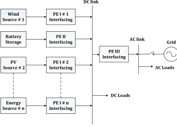
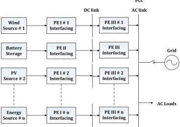
Due to the intermittent nature of RESs, the standalone wind and PV normally require energy storage devices such as battery, super-capacitor, super magnetic energy storage (SMES), flywheel, and so on. However, some RESs based DGs can complement each other. For example, PV output is high during the day whereas wind output is high during the night and vice versa; therefore, these two sources together can provide the required stable and reliable power to customers, which is referred to as a hybrid system. Similarly, a local grid consisted of dispersed loads and different DGs: dispatchable and non-dispatchable, along with or without energy storage is referred as a ‘microgrid’, which may operate in a grid connected or Islanded for small communities [6].
The concept of microgrids or many DGs at the customer’s end is mainly focused on generating an amount of power in multiple locations instead of generating a lot of power in one center; therefore, it defers the expansion of a long distance high voltage transmission line which is very expensive [7]. Furthermore, the microgrid provides the potential benefits to the customer from reliability and power quality point of view [8]. However, proper coordination is required between the sources and loads to utilize all of its useful benefits [9].
standalone or hybrid, or in a cluster such as a microgrid are still challenging tasks because there is no prominent standard specified for control and power management, especially during islanded conditions or off-grid mode. However, IEEE 1547 does provide the universal standard for interconnecting all kinds of DGs in an electric power system (grid). It provides requirements relevant to performance, operation, testing, safety and maintenance of the interconnection. But the evolution of new DGs and the different nature of the grid around the world, along with the lack of a concrete national standard, is still a challenge to the implementation of new DGs project [10].
The advancement in power electronics brings a lot of flexibility in the control strategies of non-dispatchable DGs such as wind and PV [11]. The intelligent power electronic based interfacing unit between the RES based DG and grid is changing the basic characteristics of these DGs from being an energy source to be an active power source for the grid [12]. The grid has now started demanding power at its given time from these RESs. Therefore, power management strategies for these DGs are essential to cope with all of the grid requirements. The increasing penetrations of these RESs in the grid are not only expected to increase their reliability and stability for the sake of their revenues, but also to support the grid during adverse conditions [13].
Some of the sophisticated and sensitive loads in the industries are semiconductor manufacturing, textile mills, paper mills and plastic injection molding, etc. whereas smaller commercial sensitive loads such as modern digital appliances, VCRs, microwave ovens, computers, electronic data processing equipment, and so on, are all demanding a stable and reliable power supply [14]. Nowadays, many loads are powered by RESs [15]. Therefore, even a standalone or hybrid RESs based power system requires a proper power management control strategy to meet the load demand.
and industrial/commercial power systems. Since these microgrids are not operated optimally, the energy cost and the footprint are higher than they have to be. Therefore, the current research work is mainly focused on developing control strategies for hybrid and microgrid systems with possibly reduced number of components but still maintained the same level of performance if not higher.
In summary, the deregulation of power industry, advancement in technologies, constraint in the construction of new transmission lines, customer demand for stable and highly reliable power and environmental concerns encourage to use clean and RESs, such as wind and PV in different structures such as a standalone system, hybrid system and microgrid either in islanded or grid connected mode. The intermittent nature of these RESs and non-specified standard in a hybrid and microgrid system require proper power management control strategies to meet the load demand with stable and reliable power.
1.2 Motivations
The non-dispatchable DGs such as renewable energy sources, wind and PV are utilizing broadly nowadays due to the advancement in technology, free of energy cost, less dependence on fossil fuels, and cost reductions in last few years. However, the power management control strategy for RESs is still challenging due to their weather dependency, high stability and reliable power demand and grid requirements. The advancement in power electronics provides flexibility in control, whereas increasing penetration of RESs brings issues in a grid. Similarly, increasing islanded (off-grid) applications of RESs especially with a rapidly growing DC system realizes challenges in power management. In addition, the lack of optimum control strategy for the concerned issues increase the overall cost of the system with lower efficiency. The RESs are still costly in comparison to conventional energy sources, such as gas, and diesel. Therefore, the RESs demand the cost effective system structure and control strategy to reduce the overall cost.
1.2.1 Advancement in Power Electronics
overall power generation. Although large wind farms are still being constructed all over the world, the last few years have seen increasing focus given to small scale wind turbines (< 500 kW) due to their lower impact on landscapes, lower noise levels, and their capability to operate separately from the grid in islanded communities [16]. These advantages, in turn, stem from advancements in power electronics, including improvements in the ability to cope with the intermittent nature of wind energy to meet the grid requirements. The variable speed wind turbines (VSWT) equipped with permanent magnet synchronous generators (PMSG) and full-scale power electronics-based converters are an excellent example of such advancements.
1.2.2 Grid Connected Mode
These small scale RESs are flexible in control and operation which can be used as a standalone, hybrid system or a microgrid. The standalone operation of RESs such as WPS brings lots of challenges in a grid connected and off-grid mode. In a grid connected mode, the WPS is supposed to intact with the grid at the point of common coupling (PCC) even during the adverse conditions of the grid such as fault, voltage sag and imbalanced loads etc. In the first place, the WPS should be disconnected during any ill effect at the PCC. If the increasing penetrations of these WPSs in the grid disconnects at once, then it affects the stability of the grid and could cause the catastrophic collapsing of the grid. Therefore, the grid code is designed for these RESs to be connected in the grid. The small WPS which is not sufficient itself to cure the grid problem is also asked to remain in the grid even during worst conditions at PCC. Therefore, these WPSs require a control strategy which can get rid of the effect of grid problems and remain in the grid for the specified period, according to the grid code during grid disturbances [13].
1.2.3 Islanded (Off-grid) Mode
frequency from their nominal operation [18].The integration of energy storage with the standalone operation of WPS improves the voltage and frequency responses in the presence of fluctuating wind speed and varying load demand [19]. Energy storage is capable of supplying large amounts of energy to balance power during abnormal conditions such as wind gusts and sudden load variations [20]. Battery storage is one of the best suited storage technologies for wind power applications, due to its high energy density levels [21].The off-grid WPS demands a cost effective and smaller footprint system with high level of power quality and reliability.
Microgrids can be perceived to use DC or AC voltage in the local grid, hence they can be classified into the DC and AC microgrid [22]. The DC microgrid is gaining popularity due to its attractive features such as low cost, easy control with no reactive power concern, higher energy conversion efficiency with less electronic components, modular and scalable, and recently various applications [23]-[24]. Therefore, a proper power management control strategy is required in the DC microgrid to maintain a stable and reliable power supply by considering all of its attractive features.
1.3 Problem Statement
The renewable energy source, such as a wind source, cannot operate satisfactorily within the operating limits and meet the load demand due to its intermittent nature. Some additional sources and sinks are required in order to counterbalance the fluctuating nature of the wind. With the rapid development of renewable energy and power electronics technology, cost reduction in energy storage and wider applications of the microgrid system, different control strategies and power management systems have been proposed for wind integration [163].
power is balanced within the system in all conditions and the stability of the system is also maintained by regulating the DC link voltage within the operating limits of the DC microgrid.
In contrast to the diesel generator based microgrid system in the literature where the generator is contributed constantly throughout the operation in order to counterbalance the intermittent nature of renewable sources, the developed control strategy operates the diesel generator occasionally in the presence of the battery. The proposed control strategy utilizes the local power sources owned by the community as a microgrid at maximum by deactivating the local grid. In addition, the diesel generator is activated only during abnormal (extreme) conditions, such as low battery energy storage or maintenance requirements. This strategy provides the following advantages: (i) The maximum use of local power reduces the electricity bill from the grid; and (ii) The reduction of frequent operation of the diesel generator, which cuts down the operating cost of the microgrid.
In Chapter 5, the conventional structure maintains the stability and reliability of the hybrid system by regulating the DC link voltage within the operating limits and balancing the power flow in the system irrespective of fluctuating weather and load conditions. In addition, it gives the flexibility of control, but at high structural cost. The hybrid system which is controlled with lesser power electronic components or devices not only reduces the cost, but also reduces the failure rate and maintenance period. The possible structure elements that can be removed without affecting the system performance as shown in Chapter 5, are the battery converter and a dump load. However, the challenges exist in control which requires an intelligent power management scheme to maintain the same level of power stability, and reliability of the system, which is presented in Chapter 6.
source. Therefore, the battery is charging through a regulated current value. Furthermore, the battery is charging smoothly without a high inrush current.
Therefore, the proposed control strategy in the hybrid system, presented in Chapter 6, features a power management strategy that does not require a converter for the battery, eliminates the need of a dump load and provides simple integration to the distribution network, if required, compared with a set of two standalone systems. Thus, the integration of a PMSG based VSWT in a standalone hybrid system is expected to be cost-effective and efficient.
However, the issues of balanced power flow, stable DC link voltage (DLV) within operating limits, and protection against battery overcharging and over discharging in the microgrid, cannot be solved by the integrated control strategy proposed in Chapter 6. Therefore, a distributed control strategy using a DLV based control law is proposed for a DC microgrid in Chapter 7, considering the same system configuration features: no dedicated battery converter and a dump load.
In the literature, the centralized- master/slave control, and decentralized-droop control power management strategies for a DC microgrid are commonly considered. Centralized control involves performing control action in a control center and then sending control signals to the different sources through real time high bandwidth communication links [68]. Therefore, the failure in communication links can degrade the system reliability. This issue is avoided by a decentralized control. Decentralized control refers to control action performed autonomously based on local measurements [69]. Nevertheless, this improvement is at the cost of both inaccurate power sharing or poor voltage regulation and circulating current due to the mismatch in the parallel converter’s output voltages. These issues are tackled in a droop control mechanism using a low bandwidth communication link.
distributed control for each source is incorporated. A typical distributed control strategy applied to DC microgrid is the average current sharing. This algorithm requires the average current of each source to set the voltage reference. The complexity rises with increasing number of sources. Therefore, a distributed control strategy using DLV based control law is proposed. The proposed strategy provides the following features to improve issues occurring in the literature:
(i) Unlike in a droop control, the renewable sources are operated in a current mode under the MPPT scheme as long as the source is not assigned to participate in regulating the DLV. In droop control, the sources are operated under voltage control mode to regulate the DLV together. The sources are out of MPPT scheme most of the time. (ii)Under the proposed strategy, one source at a time is operated in the voltage regulation
mode unlike in a droop control: therefore, the issues of inaccurate power sharing or poor voltage regulation and circulating current do not exist.
(iii)The proposed strategy operated in a distributed manner with local information therefore, it does not require a real time communication link as in the centralized controller.
(iv)The offline communication link is used to update the set values for sources when it requires, such as the integrating of a new sources and the revising of priority level. As a result, the renewables are at their maximum power output without frequent switching from one operating mode to another which can create a less transient effect in the system.
The issues related to DC link are studied in Chapters 5, 6, and 7 for a wind source as a hybrid system and a DC microgrid. In previous chapters, the developed control strategies are used to coordinate the sources in order to regulate the DC link voltage and maintain the DC link stability. The same concept is implemented in Chapter 8, as well, but with a grid connected wind source only. The generator side converter or DC-DC converter is used to regulate the DC link voltage and maintain the DC link stability. Therefore, issues related to the network side converter or inverter at AC link in the presence of voltage sag at the PCC is the primary focus of this chapter. The PMSG-based VSWTs that are integrated with the grid have the following issues during voltage sag:
(i) Conventionally, the controller output of the DC link voltage determines the flow of the active power, making the active power flow inaccurate to the reference. (ii) The negative-sequence currents flow from the inverter to the grid, causing
unacceptable oscillation at twice the system frequency during unbalanced voltage sags at the PCC [80]. This oscillation creates instability in the system
(iii) The imbalanced power flow occurs between the generator and the grid side inverter, causing the DC link voltage to rise abruptly with ripple during balanced voltage sags at the PCC [80], and
(i) The inverter output current can rise drastically during voltage sags.
These issues potentially may cause damage to the DC link capacitor, and the power electronic components which, in turn, forces the WPS to disconnect from the grid.
If the voltage sag issue at the PCC is not considered while developing a control strategy for a WPS, then the WPS may be disconnected from the grid or damaged during the voltage sag. In addition, the grid code is mandatory for WPS to support the grid, such as active filters or shunt/series inverters [81]. Unfortunately, this solution may not be suitable for small scale wind turbines, SSWTs (< 300 kW) in the low voltage (LV) distribution network.
Based on the issues discussed above, the following control objectives are set for PMSG-based VSWT:
(ii)The inverter control performs the following functions, depending on the conditions of the grid:
• Achieving maximum power point tracking (MPPT). • Regulating the negative-sequence currents to zero.
• Maintaining that the inverter output currents are symmetrical and at the pre-disturbance amplitude irrespective of grid pre-disturbances.
• Balancing the active power between the generator and the grid side inverter during grid voltage sags.
This configuration decouples the control objectives, allowing for the separation of control dynamics at both the generator and the grid side converter. This leads not only to the accurate flow of active power due to the direct power control, but also permits independent control of DC link voltage, and active and reactive power under the vector control strategy. An additional advantage of this control strategy is that it allows the system to ride through grid disturbances without the need to add additional components, such as a chopper to the system. Therefore, the proposed control strategy enables the wind turbine (WT) system to be optimally designed without the need for oversized converters, a large DC link capacitor and a crowbar circuit, which reduces the overall cost of the system.
However, this research work argues, if a large number of SSWTs disconnect from the LV distributed grid network (DGN) within a short period time, then the grid may also encounter instability issues. This is a foreseen condition considering the increasing penetration of SSWTs at the LV DGN. Unlike HV grid network, the LV DGN has a resistive dominant line impedance (R/X > 1), which demands more active power than reactive power to support the voltage sag [188]. Therefore, the PCF based control strategy is proposed to control the active power injection to remain in a grid during the voltage sag so that the MPPT power level can be maintained right after the fault clearance.
disturbances, but may not be effective in the presence of large disturbances, such as transient disturbances [96]. This is because PI controllers are designed based on linearized small signal models. These models become invalid under large disturbances [97]. In addition, SSWTs at the distributed grid network (DGN) are highly exposed to inherent transient disturbances, such as frequent weather fluctuations, variations in dynamic loads, and temporary faults. The reason could be the close proximity of such wind turbines (WTs) to the loads and surroundings, such as trees and buildings. These transient disturbances create stress on the PEC [184], where a large amplitude transient can shorten the life span of the components and lead to premature failures [11],[185].
In the literature, the non-linear controllers have been used in PEC such as adaptive control, hysteresis control, intelligent control, and modern control theory based controllers such as state feedback controllers and self-tuning controllers. However, most of the nonlinear controls are application dependent and difficult to design and implement, whereas sliding mode control (SMC) is an exception, as it is straightforward to design and easy to implement. Furthermore, the conventional control strategy for the grid side converter (GSC) is to carry out maximum power point tracking (MPPT) schemes, whereas the power flow in the network side converter (NSC) is determined by the DC link voltage regulation [57]. This conventional control strategy has two issues:
(i) The power flow is not accurate to the reference as the controller output of the DLV regulation determines the power flow;
(ii) The complexity arises for the implementation of SMC [103]. The number of differentiations of the output function required for the input to appear explicitly is called the relative degree of the system [186], which becomes 2 for the NSC.
(i) The reactive power is injected based on the grid code during the voltage sag to support the voltage at the grid.
(ii)The active power is the difference between the MPPT power and reactive power, so that the amplitude of converter current is maintained within the safe limits.
(iii)The VCCF in the positive synchronous reference frame (SRF) is proposed to regulate the negative sequence currents to zero during unbalanced voltage sag.
The control strategy achieved the same performance, as shown in Chapter 8, in the presence of unbalanced voltage sag at PCC, in addition to the suppressed transient effect and robustness to the parameter variations. Unlike Chapter 8, the proposed strategy is operated under the grid code (reactive power supply). In addition, the loops for feed forward terms in the control strategy proposed in Chapter 8 are eliminated with SMC approach. The complexity of the control structure is reduced.
Therefore, the power management control strategy for a WES in different power system structures: hybrid, microgrid and distribution grid, are developed to actively participate in the operation of the system with improved performance.
1.4 Objectives of the Research
The primary objectives of the research are to develop different control strategies for a WES under different structures and operating modes: islanded (hybrid/microgrid) and distribution grid network in order to maintain stable and reliable operation in the system. Thus the objectives are:
(a) To design and develop a physical hardware system in order to evaluate the developed control strategies for a power management scheme.
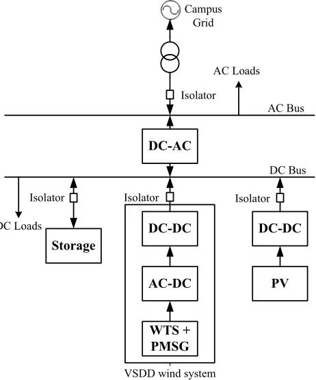
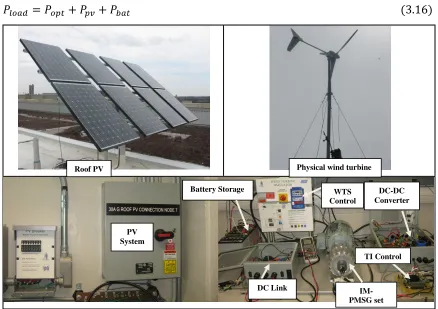
• The wind turbine simulator (WTS) is developed to mimic the steady and dynamic characteristics of a real physical 1.0 kW wind turbine on the roof of the Claudette Mackay-Lassonde Pavilion (CMLP) building at the University of Western Ontario (UWO).
• The DC and AC link buses are also developed to interface different energy sources and storage in the laboratory.
(b) To develop a comprehensive model for renewable energy sources: wind and PV, and battery energy storage system to study the power management control strategies in an islanded microgrid and a grid connected system. Furthermore, the simulation model is validated by the real physical system developed in the laboratory.
(c) To develop a power management control strategy for a wind power system along with a battery energy storage in the presence of a dedicated bidirectional converter as a hybrid system. The focus is on regulating the DC link voltage and balancing the power flow irrespective of fluctuating weather conditions and load demands. In addition, the dump loads and a diesel generator (emulated as an AC source) are also considered to protect the battery against the SOC limitations.
(d) To develop a power management control strategy for a wind power system along with battery energy storage as a hybrid system without a battery converter and a dump load. The focus is on regulating the DC link voltage and balancing the power flow irrespective of fluctuating weather conditions and load demands. In addition, the regulation of the amplitude and frequency of its terminal voltage for unbalanced load conditions is also performed.
(e) To develop a power management control strategy for a DC microgrid consists of wind, PV, battery energy storage and loads. The focus is on regulating DC link voltage and balancing the power flow irrespective of weather conditions and load demands. The control strategy is developed without a dedicated converter for battery and a dump load to increase the efficiency and reduce the cost.
(f) To develop a control strategy for a low voltage distribution grid connected WPS during voltage sag at PCC due to faults or unbalanced loads.
(g) To design a sliding mode controller for the WPS to enhance the performance during unbalanced voltage sag under the grid code. Furthermore, the comparison with a classical PI controller is also performed to show the effectiveness of the controller. (h) To validate all the developed control strategies in the laboratory based experimental
1.5 Scope of the Research
The focus in this thesis is on developing power management control strategies for a permanent magnet synchronous generator based variable speed wind turbine, a non-dispatchable DG, in different structural forms: (i) Isolated/Islanded mode as a hybrid system and a microgrid; and (ii) Grid connected mode, as illustrated through a tree diagram in Figure 1.2.
Non Dispatchable DG: Wind and PV
Isolated Mode Grid Connected Mode
Hybrid
System Microgrid
Figure 1.2: Scope of the thesis using tree diagram1
The objective of the considered structures and the developed power management control strategies broadly define the scope of this research, which are briefly introduced as follows:
(ii)Grid connected wind system: The wind system is considered to connect at the distribution grid network. Therefore, the control strategy is developed for common distribution grid disturbance- balanced and unbalanced voltage sag. However, the voltage swell which is also a problem with RES, has not been considered in this thesis. The control strategies are developed for a WES at a distribution grid with a line impedance, R/X >1 (highly resistive). In addition, the same control strategy using SMC approach is also operated under a grid code (for a low R/X ratio).
1.6 Contributions of the Thesis
The main contributions of the thesis can be summarized as:
(a) The physical hardware systems are designed and developed to validate the developed control strategies. The WTS is developed to mimic the static and dynamic characteristics of a real physical wind turbine on the roof of the Claudette Mackay-Lassonde Pavilion (CMLP) building at the University of Western Ontario. Furthermore, the design and development of power electronic based interfacing unit for a WTS, such as AC-DC converter, DC-DC converter (buck), and DC link bus, which can be interfaced to the existing DC-AC converter (inverter) in the laboratory as a PMSG based VSWT system (type IV).
a microgrid at maximum, by deactivating the grid. Moreover, the diesel generator is activated only during abnormal (extreme) conditions such as low battery energy storage or maintenance requirements. This strategy provides the following advantages: (i) Maximum use of local power reduces the electricity bill from the grid; and (ii) Reduce the frequent operation of the diesel generator, which cuts down the operating cost of the microgrid.
(c) The power management control strategy is proposed for a PMSG based VSWT along with lead acid battery energy storage as a hybrid system in an islanded (off-grid) mode. The control strategy controls the wind and battery through the same DC-DC converter and without the dump load; thus, it is referred to as an integrated control strategy. The objective of the integrated control strategy is to regulate the DC link voltage within the specified limit in order to balance the power flow irrespective of fluctuating wind speed and varying load demands and to protect the battery from overcharging. A dual vector voltage control (DVVC) strategy is also proposed at the AC side to regulate the amplitude and the frequency of AC link voltage during the unbalanced loads for an islanded hybrid system.
(d) The distributed control for power management in a DC microgrid using a DC link voltage (DLV) based control law is proposed. The operational strategy is based on the established dynamic control law which decides the operating modes: maximum power point (MPP) or voltage regulation operating (VRO) mode of the sources. The cost effective control strategy is proposed for a microgrid system (renewable dominated), which protects the battery storage against overcharging without a dedicated battery converter. Therefore, this work explains the control structure, strategy and the implementation of the distributed dynamic control law. The notable features of the proposed control strategy are: (i) straightforward implementation; (ii) less frequent mode transition; (iii) no real time communication link; and (iv) potential for plug and play. In addition, the stability analysis of the control strategy with respect to the line resistance is also performed.
work first analyzes the adverse effects of voltage sags on VSWT systems and then outlines a control strategy. The strategy consists of: (i) a vector current control with feed-forward of the negative-sequence voltage (VCCF) in order to eliminate the effect of negative-sequence components during unbalanced voltage sags; and (ii) a power compensation factor (PCF) control for the VCCF, which maintains the balanced power flow from the VSWT to the grid irrespective of voltage sag. The latter also works to keep the VSWT system’s output currents within safe limits to avoid potential damage to electronic components in the inverter. Unlike the conventional control strategy, the proposed one allows the VSWT system to use optimally sized converters without the need for large DC link capacitors and crowbars.
(f) The control strategy for a PMSG based VSWT at a grid network is further enhanced by using a non-linear sliding mode controller. The strategy not only takes care of the effect of unbalanced voltage sags, but also reduces the effect of sudden changes in the unhealthy grid by suppressing the transient effects and providing robustness to the system. In addition, the control strategy is operated under a grid code to support the voltage sag by injecting reactive power, considering line impedance, R/X<1. As a result, the VSWT remains on line without harming itself and supports the grid.
(g) The real time experiments for the hybrid, microgrid and grid connected system are performed to validate the proposed power management control strategies with the physical systems. The closed loop control algorithms are translated into versions that can operate in real-time control platforms. Different real time control platforms such as National Instrument LabVIEW, Texas Instrument (TI) C2000 microcontroller and dSPACE are used for different applications: LabVIEW is used for the control of WTS, TI microcontroller is used for the control of DC-DC converter and dSPACE is used for the control of DC-AC converter. The dSPACE is also used to gather data in real time during experiments.
1.7 Literature Review
design and development of wind turbine simulator is performed in the laboratory to support the research on wind energy sources.
1.7.1 Wind Turbine Simulator
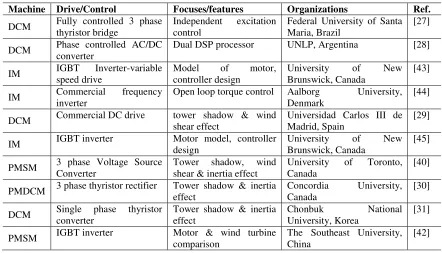
The concept of a WTS is not new, and different universities and research institutions have developed various WTSs to meet their own research needs. For example, Illinois Institute of Technology (IIT) installed the 8kW Viryd lab based wind turbine drive train system, which is used extensively for research and education [25]. In almost all WTSs, electric motors are used to realize the characteristics of the wind turbine under consideration. As a result, different types of motors lead to different WTS properties.
Three types of motors are commonly used, namely direct current motors (DCM), permanent magnet synchronous motor (PMSM), and induction motors (IM). A DCM is relatively large in size for a given power rating, expensive, and requires more frequent maintenance. However, DC motors are easy to control in order to generate the complex dynamic behavior of a physical wind turbine. A permanent magnet motor is reliable and has good power density, but it is relatively expensive. An IM is robust, inexpensive, has good power density, and low maintenance costs. However, to achieve the desired response, a more complex control system has to be used to deal with its inherent nonlinear characteristics.
A review of wind turbine simulators prior to 2000 was made in [26]. It was based on the performance of three WTS categories according to the intended use. The categories are as follows: (i) a simulator of a particular structure without specified dynamic behavior, (ii) a simulator with specific dynamic behavior, and (iii) a simulator with a general structure. The following section will review existing WTSs in the literature based on the type of motors used.
WTS Based on DC Motor
A DCM with a separate excitation and controlled by a microcomputer was used to develop a WTS at the Federal University of Santa Maria in 1995 [27]. A wind turbine emulator, another name for a WTS, was designed based on a dual digital signal processing (DSP) system at Universidad Nacional de La Plata in Argentina. It was used for developing and testing new control strategies for a wind energy conversion system [28]. A wind turbine emulator was developed to investigate the effect of oscillating torque on power quality due to wind shear and tower shadow. Both stall and pitch controlled wind turbines were emulated at Universidad Carlos III de Madrid [29].
A permanent magnet DC motor (PMDCM) driven by a thyristor based AC-DC converter was used to investigate tower shadow and inertia effects [30]. Control algorithms and implementation issues have been presented for realistic emulation of the variable characteristics of wind and rotor blades using a hardware-in-the-loop simulation concept [31]. A WTS was developed to create a controlled test environment for drive trains of wind turbines [32].
A 300 W prototype wind turbine emulator was developed in Centro Nacional de Investigacion y Desarrollo Tecnologico in Mexico to study wind energy conversion systems [33]. A wind turbine emulator was designed and implemented, with consideration given to the different requirements for the development and testing of control strategies in a doubly-fed wind power generating system [34]. The operating principles and torque characteristics of the wind turbine and DC motor were analyzed to imitate the wind turbine characteristics based on a DC motor [35].
![Figure 1.1: Ontario long term energy plan [5]](https://thumb-us.123doks.com/thumbv2/123dok_us/7768904.1278366/30.612.239.412.460.695/figure-ontario-long-term-energy-plan.webp)