Tests of advanced RF off-axis current drive techniques on DIII-D
R.I. Pinsker1,*, X. Chen1, J.M. Lohr1, C.P. Moeller1, M. Porkolab2, M.W. Brookman1, C.C. Petty1, S.J. Wukitch2,
G.M. Wallace2 and R.J. Buttery1
1General Atomics, San Diego, California, USA
2Massachusetts Institute of Technology, Cambridge, Massachusetts, USA
Abstract. The establishment of reactor-relevant radiofrequency heating and current drive techniques is a focus of work on DIII-D in the next five-year period. This paper gives an overview of the planned experimental work in the areas of (1) nearly vertically launched ECCD, (2) 'helicon' (whistlers or fast waves in the lower hybrid range of frequencies) current drive, and (3) high-field-side-launch (HFS) lower hybrid (slow wave) current drive. Each of these techniques addresses the need for efficient off-axis current drive for a steady-state tokamak reactor to supplement the bootstrap current and to provide current profile control, and each will be experimentally assessed at a coupled power level of ~1 MW on DIII-D in the next few years.
1 Introduction
A steady-state tokamak fusion reactor must have most of the plasma current self-driven by the bootstrap effect to be economically practical. Reactor design studies since the 1990s have consistently shown that along with some 'seed current' near the magnetic axis, most of the remaining non-inductively-driven current is needed in the mid-radius region. For example, the ARIES-RS study proposed [1] a combination of fast waves in the lower hybrid range of frequencies (called 'High Frequency Fast Waves' in that work) and lower hybrid slow waves to drive the non-inductive, non-bootstrap current in the outer half of the minor radius. The efficiency of the current drive, both in terms of the driven current per Watt of power absorbed in the plasma core and of the efficiency of conversion of electrical power to current drive power and of coupling the power to the plasma (rf in the cases discussed here) is critical in determining the economics of the reactor. For this reason, the DIII-D Advanced Tokamak program is exploring multiple techniques in an effort to establish efficient means of off-axis non-inductive current drive.
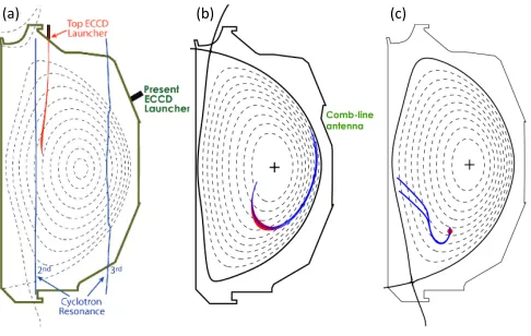
In this paper, three such techniques that will be explored on DIII-D in the next few years are described: (1) nearly-vertically-launched electron cyclotron current drive at 110 and/or 117.5 GHz, (2) 'helicon' (also known as 'fast waves in the lower hybrid range of frequencies', 'high frequency fast waves', or 'whistlers') current drive at 0.5 GHz, and (3) high-field-side-launched slow lower hybrid wave current drive (HFS LHCD) at 4.6 GHz. The three cases are illustrated in Fig. 1. Each technique will be tested on DIII-D as a proof-of-principle with ~1 MW of coupled power. Such a power level is predicted to drive sufficient non-inductive current to quantitatively compare with theoretical models and thus qualify these
techniques for next-step systems. In each case, such follow-on experiments would be possible in the future on DIII-D at power levels high enough that those systems would become viable tools for the further development of the Advanced Tokamak, along with the existing off-axis neutral beam systems on DIII-D.
2
Nearly-vertically-launched ECCD
Conventional low-field-side-launch electron cyclotron current drive (ECCD) such as is used on DIII-D (110 GHz, second harmonic X-mode) is an established technology with many applications in the DIII-D program [2]. Electron cyclotron current drive near the magnetic axis, arising from the Fisch-Boozer mechanism, on DIII-D has a predicted and observed
(a)$ (b)$ (c)$
Fig. 1. Ray tracing illustrating the three current-drive
dimensionless current drive efficiency [3] of about 0.4, where the dimensionless current drive efficiency has been normalized for the power/particle and collisionality effects and is defined as:
ζ
EC≡e3
ε
02 IECR ne
PECk Te
=3.27IEC
( )
A R( )
m ne 10 19m−3
(
)
PEC
( )
W Te(
keV)
. (1)
Reference [3] showed that the dimensionless current drive efficiency decreased as the deposition is moved to larger minor radius with the absorption location maintained to be in the midplane, due to the competing Ohkawa mechanism with opposite sign, and that this decrease is in agreement with theory. This tendency poses a problem for application of ECCD for off-axis current drive. Several authors have found that the off-axis ECCD efficiency could be significantly enhanced by changing the launch position and aiming so that the ray travels nearly vertically through the plasma at a major radius somewhat larger than that of the cold-plasma electron cyclotron absorption layer [4,5]. Use of a relatively large toroidal component to the k-vector, enabled by this geometry, allows damping on energetic electrons via the Doppler downshift and therefore more efficient current drive. Studies for DIII-D have shown a predicted improvement in dimensionless efficiency of up to a factor of two relative to outside launch for current drive at normalized minor radius of ρ=0.5-0.6, nearly recovering the efficiency of on-axis ECCD. To verify the predicted enhancement of current drive efficiency, a proof-of-principle experiment with a fixed launcher at the top of the DIII-D vacuum vessel powered by one or two existing gyrotrons will be carried out in the near future at the ~1 MW coupled power level. If the predicted improvement in current drive efficiency is experimentally demonstrated, a more flexible steerable launcher would be installed a few years later. Much more detail on this topic is given in the paper in these proceedings by X. Chen, et al.
3 Helicon current drive
Since the late 1970s, non-inductive current drive with a toroidally directive wave spectrum has been extensively studied in the lower hybrid range of frequencies (LHRF) fci << f << fce. For typical tokamak core plasma
parameters, two wave branches can propagate in this frequency range: the quasi-electrostatic slow branch, usually simply referred to as the 'lower hybrid wave', and the quasi-electromagnetic 'fast wave', also known as the 'helicon' or 'whistler' wave. To date, the most efficient non-inductive current drive technique that has been successfully demonstrated is the use of the slow wave in the LHRF [6]. It has been recognized for a long time, though, that the Fisch mechanism of high current drive efficiency (scaling as n||
−2, with n
|| the wave index of
refraction along the static magnetic field) at electron temperatures of a few keV in present devices requires accessibility of waves with high parallel phase velocities (as high as ~0.7c corresponding to a low n||≈1.5) to the
plasma core, either due to low density [7] or high
magnetic fields [8]. A further requirement is that a fraction of the wave spectrum shift to larger n|| so that it
could be absorbed by electron Landau damping (the condition n|| > 7/√Te[keV],or n|| > 2 in today’s plasmas).
Upshift of a portion of the wave spectrum is necessary to fill the “spectral gap” in n|| and maintain an energetic
electron tail pulled out from the bulk electron distribution, which is a process that follows from multi-pass toroidal ray propagation or possibly other mechanisms).We recognize, however, that this is likely not relevant for reactor-grade plasmas where the slow waves in the LHRF (henceforth simply referred to as "LH waves" here) would damp at the very edge of a large, hot, reactor-grade plasma [9] unless the waves could be launched on the high field side of the tokamak where, at typical aspect ratio, the magnetic fields are typically 70% higher than on the low field side (see Section 4 below).
For this reason, work in the 1980s began on attempts to use the other propagating wave in the LHRF for current drive, i.e. the fast LH wave [10] also known as the 'whistler' wave, or, more recently, as the 'helicon' [11]. Due to the quasi-electromagnetic polarization of this mode, with weaker rf electric field in the direction of the static magnetic field, the electron Landau damping is weaker, and the wave can reach the core of a reactor plasma with high electron beta before being strongly damped. However, in these early experiments [10] the extremely weak single-pass damping in low electron beta plasmas proved inadequate to lead to measurable current drive at high density. Recently, renewed interest in this idea led to new modeling studies [11,12]; it was found that DIII-D can now produce H-mode target plasmas with high electron beta for predicted strong single-pass damping of the helicon, and that an antenna concept proposed in 1992 [13] and developed in the mid-1990s [14] was well-suited to a proposed experimental program on DIII-D. The 'comb-line' traveling wave antenna can couple > 75% of the applied power to a highly directive spectrum peaked at n||(launch)~3, depending on the density profile in the far
SOL. Since the details of the far SOL, in the neighborhood where the local electron density is a few times 1018 m-3, are not well measured in DIII-D, the first
step in an experimental evaluation of helicon current drive was to construct and install a low-power comb-line antenna and determine the wave coupling efficiency (set by the far SOL plasma conditions) in a regime in which the core parameters are consistent with strong first-pass absorption.
The preliminary experiment was performed in 2015-2016 with the result [15] that sufficiently strong coupling to yield 75% efficiency for a toroidally longer comb-line antenna were observed in a number of regimes, and most importantly, in a regime with full first-pass absorption predicted at mid-radius. Time histories of such a discharge are shown in Fig. 2. The lowest box shows the calculated first-pass absorption for 0.476 GHz helicon waves launched at n||=3 from a
function of time; the Ohmic and L-mode portions before 800 msec in the discharge have negligible absorption (as in the 1980s experiments), while after the L/H transition signaledby the sudden drop in the D-alpha light and the consequent rise in electron beta the calculated first-pass absorption rises to 100% by 1000 msec. The quantity
Δδa (defined in [15]) plotted in the uppermost box is proportional to the measured plasma loading per element in the low-power comb-line antenna; where this quantity is larger than the dashed red line, the coupling efficiency projected to a 30-element comb-line array exceeds 75%. This criterion is easily satisfied throughout the Ohmic and L-mode portions of the discharge, and is still satisfied between ELMs through most of the ELMy portion of the shot. Only for a brief period around 2300 msec, during which an instability momentarily reduces the far SOL density (correlated with visible changes in ELM character), does the antenna loading drop below the required level; for the quasi-stationary portion of the discharge from 2500-3500 msec, the criterion is satisfied at all times at an antenna/separatrix gap of about 9 cm.
A possible issue for excitation of the helicon waves is inadvertent direct excitation of the slow lower hybrid wave. Despite the difference in polarization between the two modes at the edge of the plasma, the fact that the cut-off density for the slow wave is so much lower than that of the helicon wave would suggest the possibility of parasitic slow wave excitation. Specifically, while the 0.476 GHz helicon wave begins to propagate at a density of about 1.6×10¹⁸ m-3 for DIII-D-like parameters, the
slow wave cutoff is only 2.8×10¹⁵ m-3, a density so low
that it might be present immediately adjacent to the antenna surface during a discharge. Hence if a non-negligible component of rf electric field along the static magnetic field is present in the antenna near-field region, produced for example by a misalignment between the Faraday screen elements and the local static magnetic field, the amplitude of the fast wave fields at the cutoff might not be so much larger than the unintended slow wave fields, which would not have been reduced by evanescence. In addition to the measurements reported
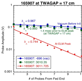
in [15], which suggested that for alignment between the magnetic field and the Faraday screen elements of better than about 10 deg the slow wave excitation appeared to be small, another piece of evidence supporting this conclusion is shown in Fig. 3. Here, direct measurements of the antenna loading deduced from fits to rf current probes in each of the twelve modules of the comb-line are shown from three times in a discharge similar to the one in Fig. 2, except the antenna/separatrix gap TWAGAP is 17 cm at around 3000 msec, compared with the 9-10 cm in Fig. 2. The slope on the semi-logarithmic plot of the probe amplitudes is inversely proportional to the antenna loading. The first measurement is a fiducial taken before the discharge starts to determine the loading due to Ohmic losses alone (no radiation), in blue. The data in green squares is in the ELMy H-mode portion of the discharge at large antenna/plasma gap, taken between two ELMs, just prior to an ELM. The slope is the same as without plasma, within the experimental error. This suggests that despite the fact that the density in the antenna near-fields probably exceeds the slow wave cutoff, the polarization must be sufficiently well defined that slow wave excitation is negligible. The ELM that occurs 1.4 msec later momentarily raises the density in the antenna near-field region above the FW cutoff and the coupling is strong, typical of what is observed in L-mode at a value of TWAGAP of ~10-12 cm. (Note that ΔδA
=0.967-0.744=0.223, comparable to the value early in 165908 before the L/H transition, shown in Fig. 2.)
Two types of nonlinear effects on antenna coupling are (i) anomalously large loading at low power levels resulting from rectified sheath dissipation in the antenna near-fields and (ii) reduction of loading at high power due to ponderomotive density depletion in the antenna near-field. An effort was made to search for evidence of sheath dissipation in the low-power experiment by scanning the power from the maximum available power of ~0.2 kW down to zero and back up in a V-shaped notch 0.1 sec wide once during each plasma shot. No power dependence of the antenna loading was ever
Fig. 2. DIII-D discharge 165908, showing a quantity
proportional to the comb-line antenna plasma loading per element in the top box, the D-alpha light at the outboard midplane in the center box, and the distance between the separatrix and the antenna surface in cm ("TWAGAP" - solid line), the calculated single-pass absorption (s.p.a.) for 476 MHz helicons (red open circles), and the line-averaged electron density (dashed line) in the lower box.
Δδa
Midplane D-alpha (a.u.)
TWAGAP (cm)
Time (ms)
Density (x 1019 m-3)
100% 50% o
o oo
o o
o o
s.p.a. (%)
0.001 0.01 0.1 1
1 3 5 7 9 11
165907 at TWAGAP = 17 cm
165907: -696 (vac)
165907: 3010.35
165907: 3011.725
Pro
b
e
Amp
lit
u
d
e
(V)
# of Probes From Fed End
At ELM Peak
Vacuum Before t=0
1.4 msec prior to ELM peak (at TWAGAP = 17 cm) δ
Α = 0.967 δ
Α = 0.960
δ
Α = 0.744
Fig. 3. Data from RF current probes built into the
observed in these power notches. If sheath dissipation were a significant portion of the total loading at low power, the fractional contribution of the sheath dissipation would change in the region where the rf sheath voltage and the local electron temperature in volts are comparable [16], a region which should be accessible even at these low power levels. Hence we conclude that the observed antenna loading in the low-power experiments is predominantly the linear wave loading. The ponderomotive effects are expected to play a role only above power levels on the order of 0.1 MW, so any such effect is a subject that can be addressed only in high-power (MW level) experiments. Since ponderomotive effects would act to reduce the loading below the linear levels, we regard the loading observed in the low-power experiments as an upper limit.
Such MW-level experiments are planned for the near future at DIII-D. At present, a high-power version of the comb-line antenna is under construction, with the principal changes from the low-power prototype being: (1) changes in the way rf power is introduced into the fed element at the 'upstream' end of the comb-line to allow excitation at up to 1 MW, (2) increasing the number of modules from 12 to 30 (this already being taken into account when the level of the dashed line indicating 75% efficiency was set in Fig. 2), and (3) reduction of the Ohmic losses (skin effect) in the modules by replacing bolted connections in the low-power version with brazed ones in the high-low-power version (also taken into account in the 75% efficiency line in Fig. 2). The several hundreds of Watts of rf power in the low-power experiments was transmitted from the feedthrough on the tokamak to the powered end of the comb-line with small-diameter sealed dielectric-insulated coaxial semi-rigid cables; these will be replaced by striplines without any dielectric materials in the high-power antenna. The stripline center conductor will be supported by quarter-wave-long shorted stubs in the vacuum vessel.
A research and development program to support the design of the high-power antenna components is ongoing at DIII-D. A test stand has been constructed with a 10 kW solid-state UHF band transmitter, a vacuum chamber and a 0.1 T solenoid in which the vacuum vessel is placed (Fig. 4). Portions of a single module of the comb-line have been tested to investigate the effect of multipactor discharges and antenna conditioning procedures and to establish upper limits on the rf voltage that can be sustained within the module without high-voltage breakdown. Such testing is performed by enclosing the module under test within a conducting box to eliminate radiation and thereby maximize the resonant 'Q' factor, which enables reaching the rf electric fields expected in 1 MW operation of the full comb-line with only 10 kW of power. In another test performed in this facility, a section of stripline was configured as a half-wavelength-long resonator and tested with several kW of rf power, for characterization of multipactor and conditioning procedures. Preliminary tests of coatings intended to reduce the secondary electron emission coefficient and thus reduce or
eliminate multipactor have been performed, without finding a clear advantage over bare copper alloy surfaces to date.
The present schedule calls for installation of the 30-module high-power comb-line into the DIII-D vacuum vessel during the present Long Torus Opening, ending in spring 2019. In parallel, a single 1.2 MW klystron obtained from the Stanford Linear Accelerator Center (SLAC) along with its power supply will be installed and tested at DIII-D. Rather than installing extensive (and expensive) runs of rectangular waveguide, existing 230 mm-diameter 50 Ohm coaxial transmission line (formerly used for ICRF experiments at up to 120 MHz) will be used to convey power from the klystron to the tokamak, a distance on the order of 100 m. Measurements of a 55-m long section of this coax in reflection from a short at one end showed that the expected loss in the entire run of 230-mm coax at 476 MHz will be approximately 0.25 dB, or 5.6% in power. A waveguide-to-coax transition is required to utilize this existing transmission line. The high-power helicon current drive experiments are planned to commence in autumn 2019.
The goals of these experiments are to verify helicon current drive efficiency that is predicted by
ray-Fig. 4. Test stand for high-power helicon antenna
tracing [12] and full-wave [17] models, (2) attempt to evaluate the importance of nonlinear effects such as parametric decay instability [18], and scattering of helicon waves from turbulent density fluctuations ('stimulated mode conversion' [19]), in addition to the non-linear effects on coupling discussed earlier. If possible deleterious nonlinear effects are ignored, the expected dimensionless current drive efficiency defined in Eq. 1 for the helicon in a discharge of the kind shown in Fig. 2 is ζHelicon ≈ 0.55 for current drive at ρ~0.5-0.6,
almost 50% more efficient than conventional ECCD at the magnetic axis in DIII-D, and hence much more efficient than conventional ECCD at mid-radius. In addition, the technological aspects of the comb-line antenna are non-trivial and themselves are an important motivation for the experiment: the 30-module comb-line will be the first MW-level traveling wave antenna tested in a magnetic confinement device, and as such is of interest for application in other frequency ranges [20].
4 High-field-side-launched LHCD
In recent years, some reactor studies have identified strong advantages to the placement of rf wave launchers on the high-field side (HFS, inboard midplane region) of the torus over the usual location in the outboard midplane region [21]. For a moderate aspect ratio torus, significant advantages of HFS launch over LFS launch for slow lower hybrid waves are particularly clear from a wave physics point of view. The highest magnetic field available in the torus is on the HFS edge, so that the minimum value of launched |n||| that can access the core
is significantly lower than from the LFS. Hence a lower value of |n||| can be launched, which makes coupling
easier for a given SOL density profile (reduced evanescence of the antenna near-fields) and the wave can reach a higher electron temperature before being strongly Landau damped. Also the lower value of |n|||
yields a higher efficiency current drive efficiency as explained earlier. Another potential advantage of HFS launch is reduced local plasma turbulence and thus weaker plasma-materials interaction. This may prove important for launcher survivability in a steady-state reactor environment. The technical difficulty of introducing a launcher on the HFS into an already existing experiment is what has to date prevented an experimental assessment of the advantages of LHCD with a launcher so located. MIT participants in the DIII-D program are leading the effort to design, install and operate the world's first HFS LHCD experiment on the DIII-D tokamak [22]. In this project, a novel compact wave launcher has been designed for installation just below the midplane on the center-post of the DIII-D device, for launching a spectrum peaked at n|| = 2.7 at 4.6
GHz at power levels over 1 MW. The launcher system obtains the poloidal/vertical split between rows of waveguides with slotted waveguides, and the toroidal split is obtained with a version of the multijunction concept. These experiments will use a subset of the 4.6 GHz system that had been used on the C-mod tokamak prior to 2016; two groups of four 0.25 MW
klystrons will be installed at DIII-D, for a total source power of 2 MW. This margin will allow for finite efficiency of the transmission lines between the klystrons and the torus, and for finite directivity of the launched spectrum. The computed directivity of the launcher is around 60%, depending somewhat on the assumed edge plasma profiles. In certain DIII-D AT regimes, the current drive efficiency predicted for this system with the combination of the GENRAY ray-tracing code and the CQL3D Fokker-Planck solver is relatively high. For example, Ref. [22] shows that for DIII-D shot 147634, an AT discharge with βN>3.5 and
qmin>1.4 (a broad current profile), the dimensionless
efficiency predicted for the HFS LHCD system is ζLH
≈
1.8, which results from 0.15 A/W driven at ρ~0.6, where the electron temperature is Te(ρ=0.6) = 2 keV and the electron density is about 4.5×10¹⁹ m-3. By comparison,
the helicon system would be predicted to drive 0.07 A/W with a flat profile within ρ≤0.6 in this discharge.
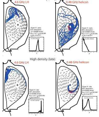
More generally, the ranges of tokamak parameter space in which the helicon and the HFS LHCD systems are most useful are complementary, in that the AT regimes in which the LH system is most useful are those with lower density and higher toroidal field, while the helicon system drives current most off-axis in the cases with low toroidal field and higher density, while high electron temperature is maintained. An example of this complementarity is exhibited in Fig. 5, where the current driven by both systems was calculated at different times in a projection along the so-called "Super-H-mode path" to high density and high plasma pressure in DIII-D. At early times and lower density, the helicon drives current at the magnetic axis, and the LH drives current at ρ~0.6, in each case at about 0.1 A/W, while at late times when the density is twice as high, the LH waves cannot access the core even from the HFS, while the helicon current drive is at ρ~0.4, at an efficiency of about 0.03 A/W. (Note that for the purposes of this comparison, the
Fri Jun 16 21:07:49 2017 ‘Super H’, late 35% absorption, 15 kA/MW driven BT=-1.9 T, Ip=0.95 MA ne(0)~9.4x10¹⁹
0.0 0.2 0.4 0.6 0.8 1.0 0 5 10 15 20
Cur Den (A/cm2)
ρ
0.0 0.2 0.4 0.6 0.8 1.0 0 2 4 6 8 10 12
Cur Den (A/cm2)
‘Super H’, late 99% absorption, 32 kA/MW driven BT=-1.9 T, Ip=0.95 MA ne(0)~9.4x10¹⁹
ρ
‘Super H’, early 81% absorption, 121 kA/MW driven BT=-1.9 T, Ip=0.95 MA ne(0)~4.4x10¹⁹
0.0 0.2 0.4 0.6 0.8 1.0 0 10 20 30 40 50 60Cur Den (A/cm2)
ρ 0.2 0.4 0.6 0.8 1.0
10 20 30 40 50 60 Cur Den (A/cm2)
‘Super H’, early 98% absorption, 132 kA/MW driven BT=-1.9 T, Ip=0.95 MA ne(0)~4.4x10¹⁹
ρ
Projection of ‘Super-H-mode’ path
Low density (early)
High density (late)
0.48 GHz helicon
0.48 GHz helicon 4.6 GHz LH
4.6 GHz LH
Fig. 5. Comparison of applicability of HFS LHCD and
location of the HFS LHCD launcher has been mirror-reflected with respect to the midplane from where it will actually be located.)
A point of practical significance for the implementation of the HFS LHCD on DIII-D is that in order to protect the feeding waveguides on the centerpost from the plasma, the thickness of the graphite tiles on the centerpost must be increased by 25 mm. Carrying out such a tile modification would mean that the wall/separatrix gap (the 'inside gap') for a geometrically identical plasma before and after the modification would differ by this amount. To investigate the effect of variation of the inside gap on confinement in AT discharges, an experiment was performed on DIII-D in which that gap was varied both dynamically and from shot to shot, in AT regimes of interest. Essentially no effect was observed, showing that installation of the modified tiles would not make comparisons of DIII-D discharges before and after the modification invalid. Another practical point regarding the installation of the launcher was the fact that DIII-D discharges always start up as limited against the centerpost so that there were concerns that the presence of a metallic structure in the region where the plasma makes contact with the centerpost could lead to unacceptable metallic impurity influx. This concern was evaluated by fabrication and installation of a mockup (unpowered) launcher built of the same materials at the same poloidal location on the centerpost as the proposed launcher. Observations of the mockup during several weeks of DIII-D operations showed no significance metallic influx from the launcher under any condition studied. Recessing the metallic face of the launcher by ~3 mm behind the carbon protective tiles appears to have been sufficient to prevent any problem with high-Z impurity influx. Of course, such a test cannot provide information on rf-specific impurities that might be generated with a powered antenna.
The present schedule for the HFS LHCD project calls for completion of the in-vessel components (launcher, modified vessel protective tiles, feed waveguides) by autumn 2019, ready for installation in the following year, with the goal being achieving high-power operation of the system in late 2020.
5 Summary and conclusion
An exciting program to investigate the physics and technology of efficient off-axis rf current drive techniques is well underway at DIII-D. The three techniques under study are: nearly-vertically-launched electron cyclotron current drive, 'helicon' current drive (fast waves in the lower hybrid range of frequencies) at 0.5 GHz, and high-field-side-launched slow lower hybrid wave current drive at 4.6 GHz. Each technique will be tested at ~1 MW coupled power levels in the next few years. The most promising technique or techniques may be expanded in subsequent years from the proof-of-principle level to higher power levels to become useful tools for the Advanced Tokamak program on DIII-D.
This work supported by the United States Department of
Energy under Award DE-FC02-04ER54698 and by US DoE
Contract No. DE-FC02-01ER54648 under a Scientific Discovery through Advanced Computing Initiative. DIII-D data shown in this paper can be obtained in digital format by following the links at https://fusion.gat.com/global/D3D_DMP.
DISCLAIMER: This report was prepared as an account of work sponsored by an agency of the United States Government. Neither the United States Government nor any agency thereof, nor any of their employees, makes any warranty, express or implied, or assumes any legal liability or responsibility for the accuracy, completeness, or usefulness of any information, apparatus, product, or process disclosed, or represents that its use would not infringe privately owned rights. Reference herein to any specific commercial product, process, or service by trade name, trademark, manufacturer, or otherwise does not necessarily constitute or imply its endorsement, recommendation, or favoring by the United States Government or any agency thereof. The views and opinions of authors expressed herein do not necessarily state or reflect those of the United States Government or any agency thereof.
References
1. S.C. Jardin, et al., Fusion Eng. Des. 38, 27 (1997) 2. R. Prater and C.C. Petty, Fus. Sci. Tech. 48, 1141
(2005)
3. C.C. Petty, et al., Nucl. Fusion 43, 700 (2003) 4. R. Prater, V. Chan, and A. Garofalo, Bull. Am.
Phys. Soc. 57, 188 (2012)
5. E. Poli, et al., Nucl. Fusion 53, 013011 (2013) 6. N.J. Fisch, Phys. Rev. Lett. 41, 873 (1978) 7. J.E. Stevens, et al., Nucl. Fusion 28, 217 (1988). 8. M. Porkolab, et al., Phys. Rev. Lett. 53, 450 (1984) 9. V.S. Chan, et al., Fus. Sci. Tech. 57, 66 (2010) 10. R.I. Pinsker, in Radio Frequency Power in Plasmas
(Proc. 10th Topical Conf., Boston, MA, 1993) (AIP,
Melville, NY) p. 179
11. V.L. Vdovin, Plasma Phys. Rep. 39, 95 (2013) 12. R. Prater, et al., Nucl. Fusion 54, 083024 (2014) 13. C.P. Moeller, et al., in Radio Frequency Power in
Plasmas (Proc. 10th Top. Conf., Boston, MA, 1993)
(AIP, Melville, NY, 1994) p. 323
14. R.I. Pinsker, et al., in Fusion Technology 1996 (Proc. 19th Symp., Lisbon, Portugal, 1996)
(Elsevier, Amsterdam, 1997) p. 629
15. R.I. Pinsker, et al., Nucl. Fusion 58, 106007 (2018) 16. D.A. D'Ippolito and J.R. Myra, Phys. Plasmas 3,
420 (1996)
17. C. Lau, et al., Nucl. Fusion 58, 066004 (2018) 18. M. Porkolab and R.I. Pinsker, EPJ Web of
Conferences 157, 03042 (2017)
19. P.L. Andrews, Phys. Rev. Lett. 54, 2022 (1985) 20. R. Ragona and A. Messiaen, Nucl. Fusion 56,
076009 (2016)
21. G.M. Wallace, et al. AIP Conf. Proceedings 1689, 030017 (2015); doi: 10.1063/1.4936482