ISSN (Print) : 2320 – 3765 ISSN (Online): 2278 – 8875
I
nternational
J
ournal of
A
dvanced
R
esearch in
E
lectrical,
E
lectronics and
I
nstrumentation
E
ngineering
(An ISO 3297: 2007 Certified Organization)
Website: www.ijareeie.com
Vol. 6, Issue 3, March 2017
A Review on Small Hydro Power Plant Model
Akhand Pratap Singh1, Atul Patni2, Divyamohan Gupta3, Dixit Malviya4 , Gaurav Bansal5
Department of Electrical Engineering, Poornima College of Engineering, Jaipur, India
ABSTRACT: This small model of a hydro power plant that generate output of 120 watt . The cost of hydroelectricity is relatively low, making it a competitive source of renewable electricity. The hydro station consumes no water, unlike coal or gas plants. The project produces no direct waste, and has a considerably lower output level of greenhouse gases than fossil fuel powered energy plants. A generating station which utilizes the potential energy of water at a high level for the generation of electrical energy is known as hydro-electric power station. As we know that the power plant is defined as the place where power is generated from a given source, so here the source is hydro that’s why we called it hydro power plant.
KEYWORDS: Small Hydro Power (SHP), water-flow rate, hydroelectricity, renewable, greenhouse
I. INTRODUCTION
A small hydropower plant cannot be considered as a smaller form of a large hydro power plant. The small hydropower plant construction planning requires a large number of technical analyses at different stages of the process with a view to determining whether a given location is technically usable, ecologically acceptable and economically justified for a project .The feasibility of a this project is specific for each location. Installed capacity of a small hydropower plant in one location depends on stream flow and water elevatation used at the location. This dependence contains some uncertainty because the amount of expected energy generation will be related to available water quantity or, will be related to the vary in stream flow duration the year. These changes have such strong impact to the generation value that they must be considered at daily and sometimes even hourly level, given the nature of the stream flow changes.
II.PROJECT SITE COMPONENT
All the following components are listed below in this section which in used in our project. Components are with their quantity and size as per our requirements.
S.No Name of Component Quantity
1 Water tank 1
2 Pen stock 1 (lenth-15 met.)
3 Turbine 1
4 Generator(Alternator) (12 volt, 10amp.)
5 Transformer As per requirement
6 Inlet and outlet valve As per requirement
7 Exciter 1
8 Water pump 1(0.25HP)
ISSN (Print) : 2320 – 3765 ISSN (Online): 2278 – 8875
I
nternational
J
ournal of
A
dvanced
R
esearch in
E
lectrical,
E
lectronics and
I
nstrumentation
E
ngineering
(An ISO 3297: 2007 Certified Organization)
Website: www.ijareeie.com
Vol. 6, Issue 3, March 2017
10 Trash rack As per requirement
11 Surge tank 150 ltr.
12 Draft tube As per requirement
Table 1. Components list
III. METHODOLOGY
The definition of criteria under which it would be possible to develop small hydropower plants at the national level, does not give results matching the situation in the field, even at the water seam level . Initial step for planning of small hydro power plants is definition of effectively feasible projects of small hydropower plants development. As a next step it is proposed to overview the potentials for activities in the space in potential locations/water streams, bearing in mind already defined and examined views concerning levels of protection of specific areas and water streams – level of strategic assessment of environmental impact. The projects (locations) which do not meet these criteria shall be ruled out from further considerations and analysis. Namely, many countries have presented theirs endeavors for maximum possible protection of environment, especially referring to technically and economically justified protection of environment and accelerated introduction of economically viable new and renewable energy sources and energy efficiency enhancement. This determination is associated with the Spatial Plan, and is translated in to legislation concerning environmental protection
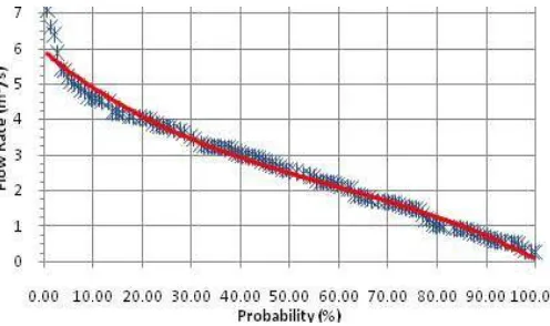
Fig-1, Flow duration curve
IV. POWER AND ENERGY POTENTIAL
Generally hydro turbines are optimized around an operating point defined by its hydraulic head, flow discharge and rotational speed. Since the design is run-of-the river type, constant head is assumed. Due to the high flow variation, the turbine would not be able to operate in the entire flow range. Therefore different flow ranges are chosen to calculate the power and energy generation potential of the project. Good turbine designs are capable of operating down to one fifth of the design flow maintaining its efficiency, so that the minimum flow rate of each window is chosen to be one fifth of the maximum.
ISSN (Print) : 2320 – 3765 ISSN (Online): 2278 – 8875
I
nternational
J
ournal of
A
dvanced
R
esearch in
E
lectrical,
E
lectronics and
I
nstrumentation
E
ngineering
(An ISO 3297: 2007 Certified Organization)
Website: www.ijareeie.com
Vol. 6, Issue 3, March 2017
Overall system efficiency of 72.2% is expected based on machinery available in the current markets. The rated power outputs for different flow ranges are calculated from the following equation.
The peak energy generation for each system size is obtained from the following equation.
The capacity factor of the power plant is an indication of the utilization of its total potential. This is also known as the pant factor and it is the ratio of average expected energy generation to the potential maximum energy generation.
The following table shows the calculated values for each flow window considered.
Max Min
Flow Rated
Max Est Capac ity Tur b Tur b Energ y Energ y S.N
o Rang
e Power
Facto r Flo
w Flow (m3/ Gen Gen
s) (kW) (%)
(m3/ s)
(m3/
s) (GWh)(GWh)
1 1.18 0.25 0.93
752.2
0 6.59 0.75 11.45
2 1.61 0.32 1.29
1026.
30 8.99 1.41 15.68
3 2.08 0.42 1.66
1325.
90 11.61 2.51 21.59
4 2.50 0.50 2.00
1593.
63 13.96 3.59 25.73
5 3.03 0.61 2.42
1931.
49 16.92 5.10 30.16
6 3.56 0.71 2.85
2269.
34 19.88 6.98 35.13
7 4.11 0.82 3.29
2619.
94 22.95 9.02 39.32
8 4.32 0.86 3.46
2753.
80 24.12 9.51 39.40
9 4.72 0.94 3.78
3008.
78 26.36 10.19 38.67
10 6.59 1.32 5.27
4200.
82 36.80 10.98 29.85
Table – 2, Power and energy generation
ISSN (Print) : 2320 – 3765 ISSN (Online): 2278 – 8875
I
nternational
J
ournal of
A
dvanced
R
esearch in
E
lectrical,
E
lectronics and
I
nstrumentation
E
ngineering
(An ISO 3297: 2007 Certified Organization)
Website: www.ijareeie.com
Vol. 6, Issue 3, March 2017
Fig-2, Projected energy generation v/s capacity
V .WORKING
plants capture the energy of falling water to generate electricity. A turbine converts the kinetic energy of falling water into mechanical energy. Then a generator converts the mechanical energy from the turbine into electrical energy.
Parts of a Hydroelectric Plant
Dam -Raises the water level of the river to create falling water. Also controls the flow of water. The reservoir that is formed is, in effect, stored energy.
Turbine - The force of falling water pushing against the turbine's blades causes the turbine to spin. A water turbine is much like a windmill, except the energy is provided by falling water instead of wind. The turbine converts the kinetic energy of falling water into mechanical energy
Generator - Connected to the turbine by shafts and possibly gears so when the turbine spins it causes the generator to spin also converts the mechanical energy from the turbine into electric energy. Generators in hydropower plants work just like the generators in other types of power plants.
Transmission lines. Conduct electricity from the hydropower plant to homes and business.
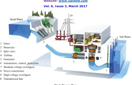
. VI. PROCESS DIAGRAM
Basic block diagram of hydro power plant model and process flow. Which is shows working, operation of power plant.
ISSN (Print) : 2320 – 3765 ISSN (Online): 2278 – 8875
I
nternational
J
ournal of
A
dvanced
R
esearch in
E
lectrical,
E
lectronics and
I
nstrumentation
E
ngineering
(An ISO 3297: 2007 Certified Organization)
Website: www.ijareeie.com
Vol. 6, Issue 3, March 2017
Fig 4. Process Flow
VII. COST ESTIMATION
As per our specification the cost of components that we used in this project is as following.
S.No. Component Name Rating Component
Requirement
Cost
1. Water tank 50 lit. 1 200/-
2. Mechanical Support 4feet 1 400/-
3. Turbine (35cm.,250-
300rpm)
1
250/-4. Generator(Alternator) 12 volt, 10 amp,20W
1
2000/-5. Bearing 22-25mm 4
200/-6. Water Pump As Per Requirement 1
800/-7. Shaft 25mm ,80cm 1
-8. Pulley 25mm 1
50/-9. U coupling As Per Requirement 1
Table 3. Cost table
VIII. CONCLUSIONS
ISSN (Print) : 2320 – 3765 ISSN (Online): 2278 – 8875
I
nternational
J
ournal of
A
dvanced
R
esearch in
E
lectrical,
E
lectronics and
I
nstrumentation
E
ngineering
(An ISO 3297: 2007 Certified Organization)
Website: www.ijareeie.com
Vol. 6, Issue 3, March 2017
Appendix
The notation used in this paper is as follows: P – Power
E – Energy
η – Efficiency of the system ρ – Density of water (kg/m3) g – Gravitational acceleration Q – Volumetric flow rate of water (m2/s) t – Hours per year
n1 – Start of flow window (minimum) nn – End of flow window (maximum)
Nk – Absolute probability of given flow rate occuring Hn – Net head
V – Water jet velocity N – Number of nozzles ds- Water jet diameter
D – Turbine runner diameter Z – Number of buckets
Un - Tangential speed of the turbine wheel in m/s. r – Radius of the turbine wheel.
ω – Rational speed of the turbine in rad/s. Egen - Annual Electricity Generation (GWh)
αCO2 - Baseline CO2 reduction factor for SHP in Sri Lanka
REFERENCES
[1]. British Hydropower Association, www.british-hydro.org visited on 1 May 2011
[2].Scientific and technological reference energy technology indicators, Working Document, European Small Hydropower Association, 2010.
[3].Celso Penche, Layman’s Guidebook on how to develop a small hydro site, Handbook, European Commission, 1998.
[4].Small Hydro Power Handbook, http://www.smallhydropower.com/manual3.htm ,visited on1 May 2011.
[5].Matlab/Simulink SimPowerSystems, Product Documentation, www.mathworks.com/help visited on 1 May 2011
[5].Zoeb Husain, Zulkirfly Abdullah, Zainal Alimuddin, Basic Fluid Mechanics and Hydraulic Mechanics, BS Publications, 2008.
[6]. Tze-Fun Chan, (2003), Synchronous Machines, in Encyclopedia of Life Support Systems (EOLSS), Eolss Publishers, Oxford UK, 2003.