Speed Sensorless Vector Control of Induction Motor Using
Reduced Order Extended Kalman Filter
AkashP
1
P
, Mahadevi BiradarP
2
PG Scholar P
1
P
, ProfessorP
2
Department of EEE
Poojya Doddappa Appa College of Engineering, Kalaburagi, Karnataka, India.
Abstract
Vector control is a speed control technique used to obtain fast and accurate speed control of induction motor. Speed sensors degrades reliability hence speed sensorless speed control is proposed. This work presents accurate electrical parameter estimation such as flux, torque, theta and speed using reduced order extended Kalman filter based induction motor control is proposed. The Kalman filter is based on the minimization of the estimation error and it is suitable for obtaining high accuracy estimates of state variables and model parameters and eliminating measurement noises. Here no need of speed, torque, flux, rotor position and stator voltage sensors, alternatively the stator current will be measured by three current transformers (CT’s) with supporting of mathematical equations. The proposed method has some advantages of saving computation time in comparison with the full order extended Kalman filter. The proposed work is implemented by a hardware using DSPIC30F4011 controller and simulated with help of MATLAB SIMULINK R2010a version. Keywords—.Vector control, Extended Kalman filter, Current
transformers, Speed sensorless, Coordinate transformation
1. Introduction
The induction machine is the heart of the most widely used form of electrical AC drive. Induction motor can be considered as the workhorse of the industry. Induction motors are classified into single phase induction motor and three phase induction motor based on given input supply. Three phase induction motors are the most common motors used in industrial control systems and commercial applications. In the past, induction motors were preferred only for constant speed applications. Adjustment of speed of induction motor was very difficult and also needs high cost. But the rapid growth in power electronics and semiconductor technology results, many kinds of induction motor variable speed drives have been developed and now the induction motors are very good alternative for variable speed applications. The robustness, low cost, the better performance and the ease of maintenance make the induction motor advantageous in many industrial applications for general applications. A fast and controlled speed response from an induction motor is obtained most effectively if the principle of vector control is used.
Vector control method is also called as field oriented control method. Vector control method is valid for both steady state as well as dynamic state conditions. In vector control it controls not only the amplitude, frequency but also their phase angle. The main disadvantages are the huge computational capability and accurate measurements of the motor parameters are required. In the direct vector control, information about the actual values of the magnitude and position of the rotor flux and rotor speed is necessary. Vector controlled induction motor drives are widely used in the industrial applications where high performance, like fast torque and speed responses, are demanded. The main concept of vector control is to decouple the control of induction motor's flux and torque via coordinate transformations and to control not only the amplitudes of current and flux but also their phase angle
.
The Kalman filter is based on the minimization of the estimation error and it is suitable for obtaining high accuracy estimates of state variables and model parameters and eliminating measurement noises. A lot of researches are carried out to develop accurate speed estimation techniques. To obtain accurate, high performance like fast torque, speed responses and more reliable in three phase induction motor drive system the vector control method has been proposed. The work is mainly focused on speed sensorless speed control of three phase induction motor using vector control technique through reduced order extended Kalman filter. For this purpose of modelling and design of induction motor drive I am developing hardware and simulating with help of MATLAB SIMULINK R2010a version.
2. Modeling of Induction Motor
The IM mathematical model may perhaps be explained in the rotating direct–quadrature (d-q) frame as given below where id and iq, Vdand Vq,ωr, TL,ψrdand θrepresents stator currents, stator voltages, rotor speed, load torque, direct-axis rotor flux, and flux angle, correspondingly. Parameter τr= Lr/
Rrindicates the rotor time constant and 𝜎= 1− 𝐿2𝑚⁄𝐿𝑠𝐿𝑟
⎩ ⎪ ⎪ ⎪ ⎪ ⎨ ⎪ ⎪ ⎪ ⎪ ⎧ did
dt =−
LrRs+ L2mRr
σLsL2r +
Lm
τrσLsLrψrd+ pωriq+
Lm
τrψrdiq 2+ 1
σLsVd
diq
dt =−
LrRs+ L2mRqr
σLsL2r iq−
Lm
σLsLrpωrψrd−pωrid+
Lm
τrψrdidiq+
1 σLsVq
dθ
dt = pωr+τLm rψrdiq
dψrd
dt =− 1 τrψrd+
1 τrLmid
dωr
dt = pLm
Lr ψrdiq−
1 J TL
(1)
In order to simplify the investigation, fix m =
(LrRs+ L2mRr)⁄σLsL2r,γ= Lm⁄σLsLr,ς= 1⁄σLs, k =
1⁄τr,ρ= pLm⁄Lr, and (1) can be modified as follows:
In this work, only the stator currents are necessary to be computed for control calculations, thus leading to a sensorless induction drive system.
⎩ ⎪ ⎪ ⎪ ⎪ ⎨ ⎪ ⎪ ⎪ ⎪ ⎧ did
dt =−mid+ kγψrd+ pωriq+ kψLm rdiq
2+ςV d
diq
dt =−miq− γpωrψrd−pωrid−kψLm
rdidiq+ςVq
dθ
dt = pωr+ kψLm rdiq
dψrd
dt =−kψrd+ kLmid
dωr
dt =ρψrdiq−1J TL
... (2)
3. Design of Reduced order Kalman filter
In this approach, the three-phase stator currents are the solitary
essential measurements, and these are converted from the
three-phase reference frame to a diphase reference frame, and
subsequently to the frame of the rotating field (d-q) as given
below: ⎩ ⎪ ⎨ ⎪ ⎧i
d=�23 2
�cos�θ��ia+ cos�θ� −23π�ib+ cos�θ�+23π�ic�
iq=�23 2
�−sin�θ��ia−sin�θ� −23π�ib−sin�θ�+23π�ic�
(3)
Where𝑖𝑎, 𝑖𝑏 and 𝑖𝑐signifies the three-phase stator currents, correspondingly and 𝜃�represents the estimated flux angle. 𝑉𝑑,
𝑉 𝜃�
The stator flux vector Ψ𝑒𝑠𝑡 and the torque generated by the motor, T𝑒𝑠𝑡, can be estimated with the help of (1) and (2), correspondingly.
φsd =�(Vsd−Rs. isd) . dt
φsq =�(Vsq−Rs. isq) . dt
…4
The previous equations only need the stator resistance Rs. The magnitude of stator flux is decided by
Ψest=�(φsd2+φsq2)
At this moment, with the stator flux and the diphase reference frame from the stator currents, together with the motor poles 𝑃, Torque is estimated depending on the equation below.
Test=32 P(φsd. isq− φsq. isd) … (5)
Where,𝜑𝑠𝑑 and 𝜑𝑠𝑞 represents the stator flux, 𝑖𝑠𝑑 and 𝑖𝑠𝑞 represents the stator currents Estimated Flux angle can be computed from the equation given below.
θ= tan−1�φsqφsd� … (6)
3.1
Speed sensorless speed estimation
With the intention of estimating the sensor less speed, the estimated stator flux has to be transformed into rotor flux depending on the magnetizing inductance in addition to the secondary inductance per phase.
𝜑𝑟𝑑=𝐿𝑚
𝐿𝑟𝜑𝑠𝑑; 𝜑𝑟𝑞= 𝐿𝑚
𝐿𝑟𝜑𝑠𝑞 .….. (7)
Square of rotor flux, 𝜑𝑟𝑑2+𝜑𝑟𝑞2
For the purpose of determining the speed of rotor field, the achieved rotor flux has to be transformed into 𝛼, 𝛽 coordinates, by means of the transfer function.
Speed of rotor field = (𝜑𝑟𝑑× 𝜑𝑟𝛽)−(𝜑𝑟𝑞× 𝜑𝑟𝛼) ….(8)
3.2
Speed control
The function of participation of the PI adjuster is to fine-tune the speed in a small range to make sure the speed tracking precision and the final zero static state error.
In the same way, for the purpose of obtaining the desired𝑉𝑠𝑞, the obtained reference torque and the estimated torque from sliding mode observer is managed through the torque PI adjuster to achieve the zero static state torque error.
𝑉𝑠𝑞=�𝑇𝑟𝑒𝑓− 𝑇𝑒𝑠𝑡� �𝐾𝑝𝑇+𝐾𝑆𝑖𝑇� ..(10)
Stator Flux Reference
Ψ𝑟𝑒𝑓=𝜑𝑟𝑒𝑓∗𝜔𝑏𝜔𝑒𝑠𝑡 …(11)
Where 𝜔𝑏= 157 𝑟𝑎𝑑/𝑠 represents the consider base speed 𝜑𝑟𝑒𝑓= 0.95. 𝜔𝑒𝑠𝑡 is
acquired from the sliding mode observer.
..….(11)
𝑉𝑠𝑑=�Ψ𝑟𝑒𝑓− Ψ𝑒𝑠𝑡� �𝐾𝑝𝜑+𝐾𝑆𝑖𝜑� ..(12) ….(13)
In the same way for the purpose of obtaining the desired 𝑉𝑠𝑑, the obtained stator flux reference and the estimated stator flux from sliding mode observer is managed through the torque PI adjuster to achieve the zero static state flux error.
The obtained d-q frame voltages 𝑉𝑠𝑑 and 𝑉𝑠𝑞 are subsequently given as feedback to the sliding mode observer to approximate the necessary electrical constraints of the induction motor. This evaluation is performed by taking simply stator current. Inverse park transformation is exploited to transform the diphase voltage (𝑉𝑠𝑑 and 𝑉𝑠𝑞) into a three phase voltage (𝑉𝑎 , 𝑉𝑏and 𝑉𝑐) which is then taken as input to the Space Vector Pulse Width Modulation.
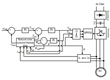
4. Block diagram and its explanation
The figure1 shows the complete block diagram of the proposed work, it consists of three phase diode bridge rectifier, DC link capacitance filter, three phase VSI inverter, reduced order extended Kalman filter (sliding mode observer). The operation of the proposed system is managed by reduced order extended Kalman filter (sliding mode observer) and Pulse Width Modulation. In this proposed system, there is no necessity for speed, torque, flux, position and also voltage measurements. The sliding mode observer has the capacity to perfectly approximate the speed, flux, theta and torque with the help of the phase currents sensing alone.
Fig. 1 Block diagram of the proposed system
The single phase input ac voltage is rectified to dc voltage by means of diode rectifier and then the DC link voltage VRdcR is given as input to the three phase voltage source inverter. The three phase VSI converts dc supply into three phase ac supply. The SPWM control technique to get the desired output from VSI. Then this three phase ac supply is given to stator of the three phase induction motor. Initially the three phase stator currents are measured through current transformers and then they are converted into two phase by axis or co-ordinate transformation using phase angle(θ) which is generated byreduced order extended Kalman filter and then these two phase stator currents iRsqR and iRsdR are given as input to the reduced order extended Kalman filter.
Then these two phase voltages VRsq Rand VRsd Rare converted back by inverse transformation using phase angle (θ) and these three phase reference voltages are given to PWM driver unit. The driver unit uses sinusoidal PWM technique compares the carrier signal(triangular wave) and the given three phase reference signal(sinusoidal wave) and generates the PWM pulses of width varied according to the three phase reference voltage signal and these PWM signals are given to the MOSFET switches in the VSI for switching action . As the three phase reference voltage is varied according to the set speed and in turn PWM signal pulse width is varied according to the three phase reference voltage and in turn the output of VSI is varied according to the PWM pulses and in turn the input of the motor is the output of VSI and in turn the speed of motor is varied as the input of the motor is varied, hence we will get desired set speed and this type the speed of three phase induction motor is controlled.
4. Simulation results and discussion
Fig 4.1 Block diagram of complete simulation system
The Block diagram of the complete simulation system is shown in Figure 4.1. Thesimulation of the work is simulated for the time duration from 0.0 seconds to 2.0 seconds and the results are observed and they are presented below.
CASE: Given step input for a speed 1000r.p.m from 0.0 to1.0 seconds and 600r.p.m from 1.0 second to 2.0 seconds:
Fig 4.2 a) Set speed v/s actual speed, b) Electromagnetic torque, c) Stator current iRa Rwaveforms
From the figure 4.2(a) it is clear that the speed of the induction motor is catching the set speed 1000 rpm from 0.0 to 1.0 sec and 600 rpm from 1.0 to 2.0 seconds.
From the figure 4.2(b) it can be concluded that the torque is remaining constant of magnitude 2N-m.
From the figure 4.3 the three phase stator currents of magnitude 3.5A, 65 Hz frequency for duration 0.0 to 1.0 second and same magnitude but frequency of 40 Hz for duration from 1.0 to 2.0 seconds. The three phase stator currents are sinusoidal in shape and are balanced that is all three phase have same magnitude with 120P
0
P
phase difference and the frequency of three phase stator current is varying according to the change in speed by keeping magnitude constant.
Fig 4.4 a) VRalpha beta R, b) Stator flux waveforms
From the figure 4.4(a) VRalpha beta Ris of magnitude 220 volts for duration 0 to 1.0 second and magnitude of 130 volts for duration 1.0 to 2.0 seconds. The two phase stator voltage VRalpha
beta Ris two phase sinusoidal voltage and whose magnitude is varying according to the speed change.
From the figure 4.4(b) it can be concluded that the stator flux is remaining constant of magnitude of 1 Weber. The stator flux is sinusoidal and two phase containing both quadrature and direct components of stator flux and it is maintained to constant magnitude of 1 Weber irrespective of speed change.
Fig 4.5 a) VRdc R, b) Three phase reference voltage waveforms From the figure 4.5(a) it is clear that the VRdc Ris the pulsating dc voltage approximately magnitude of 325 volts remaining constant.
From The figure 4.5(b) three phase reference voltageR Ris of magnitude 220 volts for duration 0.0 to 1.0 second and magnitude of 130 volts for duration 1.0 to 2.0 seconds. The three phase reference voltage is sinusoidal voltage and whose magnitude is varying according to the speed change.
Fig 4.6 PWM signal waveform
5. Experimental setup and its results
Fig. 5.1 Experimental set up of hardware
The figure 5.1 shows the experimental set up of the hardware unit. It consists of single phase ac power supply, three phase diode bridge rectifier, dc link capacitor filter, three phase voltage source inverter, current transformers, control relay circuit, DSPIC30F4011 Controller, MOSFET driver unit and three phase induction motor.
The hardware is connected as shown in figure 5.1. The required supplies are turned on then the motor starts to run. The speed of motor is set to 1000 rpm and the three parameters are measuring through Digital Storage Oscilloscope are stator voltage, stator current and PWM pulses and they are represented below
The figure 5.2 shows the stator voltage waveform of peak to peak magnitude of 8.4 volts and rms magnitude of 2.42 volts with frequency 52.28 Hz.
Fig 5.3 Stator current waveform
The above figure represents the stator current waveform. The magnitude of stator current is approximately 0.3 amps, 50 Hz.
Fig 5.4 PWM pulses waveform
6. Conclusion
A model to control the speed of three phase induction motor by vector control method using reduced order extended Kalman filter has been successfully implemented for ½ HP, 440V, 0.75A, 50Hz three phase induction motor. The hardware of proposed work is implemented by using DSPIC30F4011 controller and the work is simulated with help of MATLAB SIMULINK R2010a version. The outputs of simulation and hardware are taken and are found quite satisfactory. The stator voltage of peak to peak magnitude of 8.4 volts and r.m.s magnitude of 2.42 volts with frequency 52.28 Hz is obtained. The magnitude of stator current is approximately 0.3 amps, 50 Hz and the PWM pulse is of magnitude 260 volts. The accurate and fast speed control is achieved. The accuracy of speed control is achieved by minimizing estimation errors by using reduced order extended Kalman filter. A fast control is achieved by saving computation time compared with full order Kalman filter. The accuracy and reliability of system is improved by replacing the speed sensors with current transformers. The problem as dynamic response and coupling effect of scalar control are solved. The problem of speed sensors as error in measurement itself and low reliability are solved. Easy of maintenance due to not present of mechanical commutators, bushes, slip rings and speed sensors. Performance of proposed drive has been found quite satisfactory by accurate and fast controlling the speed of three phase induction motor. This type of speed control of three phase induction motor can be used in industries where a high performance drive like fast and accurate speed control and high reliability is required.
References
[1] Young-Seok Kim, Sang-Uk Kim and Iee-Woo Yang “Implementation of a speed sensor-less vector control of induction motor by reduced-order extended Kalman filter" in Applied Power Electronics Conference and Exposition, APEC '95. Conference Proceedings 1995, Tenth Annual, vol. no.0, vol.1, 5-9, Mar 1995, pp.197-203
[2] G.Garcia Soto, E.Mendes and A.Razek "Reduced-order observers for rotor flux, rotor resistance and speed estimation for vector controlled induction motor drives using the extended Kalman filter technique" in Electric Power Applications, IEE Proceedings - vol.146, no.3, May 1999, pp.282-288
[3] Young-Real Kim, Seung-Ki Sul and Min-Ho Park "Speed sensorless vector control of induction motor using extended Kalman filter" in Industry Applications, IEEE Transactions on , vol.30, no.5, Sep/Oct 1994, pp.1225-1233
[4] A. Dell'Aquila, F. Cupertino, L. Salvatore and S. Stasi "Kalman filter estimators applied to robust control of induction motor drives" in Industrial Electronics Society, 1998. IECON '98. Proceedings of the 24th Annual Conference of the IEEE, vol.4, 31 Aug-4 Sep 1998, pp.2257-2262
[5] Li-Cheng Zai, Christopher L. DeMarco and Thomas A. Lipo "An extended Kalman filter approach to rotor time constant measurement in PWM induction motor drives," in Industry Applications, IEEE Transactions on, vol.28, no.1, Jan/Feb 1992 pp.96-104
[6] TsugutoshiOhtani, Noriyuki Takada and Koji Tanaka"Vector control of induction motor without shaft encoder," in Industry Applications, IEEE Transactions on , vol.28, no.1, , Jan/Feb 1992, pp.157-164
[7]Juanjuan Sun and Yongdong Li "Voltage-Oriented Vector Control of induction motor: Principle and dynamic performance improvement" in1T1TPower Electronics and Applications, 2009. EPE '09. 13th European Conference on, vol, no. 8-10 Sept. 2009 pp.1-10
[8] Francesco Alonge, FilippoD’Ippolito and AntoninoSferlazza"Sensorless Control of Induction-Motor Drive Based on Robust Kalman Filter and Adaptive Speed Estimation" in1T1TIndustrial Electronics, IEEE Transactions on1T1T, vol.61, no.3, March 2014 pp.1444-1453
[9] AsgharTaheri and Mohsen Mohammadbeigi "Speed sensor-less estimation and predictive control of six-phase induction motor using extended kalman filter" in1T1TPower Electronics, Drive Systems and Technologies Conference (PEDSTC), 2014 5th1T1T, vol., no., 5-6 Feb. 2014 pp.13-18
[10] Bimal K. Bose “Modern Power Electronics and AC Drives” published by Dorling Kindersley (India) Pvt. Ltd. Sixth Impression, 2009
Author’s profile:
Akash, PG Scholar Dept of EEE, Poojya Doddappa college of engineering,
kalaburagi, Karnataka, India, [email protected]
Mahadevi Biradar, Professor, Dept. of EEE, Poojya Doddappa Appa