Miniaturized Multistubs Loaded Rectangular Monopole Antenna for
Multiband Applications Based on Theory of Characteristics Modes
Ashok Kumar1, *, Jitendra K. Deegwal2, and Mahendra M. Sharma3
Abstract—A miniaturized rectangular monopole antenna (RMA) integrated with a T-shaped stub, inverted long and short L-shaped stub resonators based on application of the theory of characteristic modes (CMs) is investigated for multiband operation. CMs of embedded multistubs resonators on the RMA are examined and perceived that the entire structure is able to excite magnetic and electric CMs, in which three valuable CMs at 2.69/3.68/5.35 GHz are attained to cover WiMAX and WLAN bands. Based on CM analysis, the design formulation of multistubs resonators loaded antenna is presented. The proposed multiband antenna has been fabricated, tested, and experimentally characterized. The measured fractional bandwidths (FBWs) are 7.03% (180 MHz, 2.47–2.65 GHz), 10.43% (360 MHz, 3.27– 3.63 GHz), and 11.42% (630 MHz, 5.20–5.83 GHz). The antenna exhibits isolated multiple frequency bands, stable monopole-like radiation patterns, and flat realized gains over the operating resonance bands while maintaining the small antenna size.
1. INTRODUCTION
The theory of characteristic mode (TCM) is a new mechanism to design and analyze the functionality of antennas in a free space to calculate resonance modes, modal currents, and radiated fields, which was first proposed by Garbacz in 1965 [1] and reformulated by Harrington and Mautz in 1971 [2, 3]. It provides fascinating physical insights into current and radiation phenomena of each mode of an arbitrarily shaped radiating body taking place in various kinds of antennas and could be efficiently optimized along with choice of feed technique to excite desired modes [4]. Numerous antennas for various wireless communication applications based on TCM have been reported [5–12]. It is used for the analysis and design of different categories of antennas such as an ultra-wideband (UWB) antennas [7, 8], planar bevel-shaped and C-shaped monopole antennas [9, 10], loop and printed inverted-F antennas [11], and slotline antennas [12] for diverse applications.
Conversely, numerous varieties of microstrip-fed/coplanar-fed multiband planar slot/monopole antennas without CM theory have been reported and experimentally characterized [13–28] using various kinds of techniques mainly embedding/etching single/multiple stubs/strips/slots/parasitic elements of length in the order of one-fourth or half of guided wavelength (λg/4 orλg/2) that can explore multiple operating frequencies. To attain multiple operating resonances mainly to cover WLAN and WiMAX wireless standards, embedding a pair of T-shaped strips in a staircase wide rectangular slot antenna [13], a fractal Koch shaped slot antenna [14], three parallel rectangular open slots etched in the ground plane of the printed antenna [15], a pair of inverted-L slots in the ground plane and loaded split-ring resonator (SRR) in circular split-ring antenna [16], a dual-split-ring resonator loaded wide-slot fork-like monopole antenna [17], a bow-tie antenna [18], a dual U-shaped strips monopole antenna [19], a pair
Received 20 February 2019, Accepted 30 April 2019, Scheduled 13 May 2019
* Corresponding author: Ashok Kumar ([email protected]).
of edge resonators loaded bevelled square monopole antenna [20], a claw-shaped monopole antenna with modified ground plane [21], three λg/4 length of inverted L-shaped strips loaded antenna [22], an asymmetric split-ring resonator patch antenna [23], a crooked U-shaped and three straight strips loaded S-shaped strip rectangular ring antenna [24], fork-shaped strip width with modified ring and a rectangular defected ground structure (DGS) antenna [25], a λg/4 length of inverted L-shaped stubs and integrated horizontally T-shaped stub monopole antenna [26], and a slotted bowtie antenna [27] are demonstrated. However, these slot and monopole multiband antennas have a large volume for the limited space of wireless terminals. So far, a pair of symmetrical edges and a T-shaped stub resonator loaded miniaturized U-shaped monopole antenna [28] is presented for WLAN and WiMAX operation, but the antenna has a complex structure, very small peak gain about 1.1 dBi at 2.45 GHz and 1.9 dBi at 3.5 GHz operating bands along with larger ground plane area due to T-shaped stub resonator and a pair of rectangular strips, which limit its applications.
Correspondingly, the alternative techniques to achieve distinct multiple operating bands and reduce the size of antennas are the coupled-resonator-based circuit modal [29], fractal geometries [30], metamaterial-inspired structures [31], loading shorting metallized vias/pins [32], and hexagonal fractal loop antenna with DGS [33]. Aforementioned techniques based antennas may suffer from complexity of the design, difficulty in fabrication, nonstability of radiation patterns, and difficulty in accomplishing additional operating resonances. For instance, in [32], a multiband operation is achieved by etching inverted multiple U-shapes and reduction in size by loading shorting vias, but the antenna has very narrow operating bands and complex structure.
In this article, a low-profile miniaturized multiband monopole antenna loaded with multistubs resonators based on TCM with monopole-like stable radiation patterns and flat peak gain at each operating band is introduced for WLAN and WiMAX wireless standards. The antenna has different current distributions on multistubs resonators to excite diverse characteristic modes (CMs) in accordance with the TCM. The triple operating bands and their resonances can be adjusted by tuning the coupling between multistubs resonators.
The CMA of the proposed multistubs loaded antenna is discussed in Section 2 with theory of CMs. The antenna configuration, design formulation for multistubs resonators, and parametric analysis are discussed in Section 3. The experimental results of constructed prototype and broad outcomes of the study are presented in Sections 4 and 5, respectively.
2. CHARACTERISTICS MODE ANALYSIS 2.1. Theory of Characteristic Mode
TCM is a technique to calculate a set of current modes for arbitrarily shaped perfect electric conducting (PEC) bodies in free space. It can gives valuable information for antenna design such as resonant frequencies and radiating modes of irregularly shaped antennas to excite particular CM without using feed port in the structure. Generally, CMs are analyzed by using eigenvalues, modal significance, characteristic angle, characteristic current distributions, and field radiations [4]. The CMs can be computed by using a base eigenvalue Equation (1) with the help of following formula:
X(Jn) =λnR(Jn) (1)
whereRandXare the real and imaginary parts of generalized impedance matrix;λnis the characteristic eigenvalue of nth mode; and Jn is the eigencurrent of the nth mode. The eigenvalue λn is the ratio of reactive power Prect, n to radiative power Prad, n of the nth mode (λn = Prect, n/Prad, n), and it is an important parameter to analyse the modes and radiation information of the CM [8]. Modes with small λn are the effective radiating modes of planar antenna, while those with largeλn are very poor radiating modes. In some situations, the eigenvalue against frequency plot has a very large λn, then it is difficult to distinguish these modes. Therefore, modal significance (MS) and characteristic angle (αn) are introduced to analyze the radiation capability of each mode.
The MS is the normalized form of eigenvalue and can be computed by using Eq. (2) as:
MSn= 1 1 +jλn
MS is considered to determine the modal resonance. Modes with small λn (whereλn= 0 at resonance) are good radiators, and those with large λn are poor radiators. At any frequency, the most significant CM is defined by the CM with the maximum valued MSn. When a mode is in resonance, the value of MSn= 1 (i.e., maximum value), and modes which do not contribute to the resonance and field radiation are defined by MSn= 0 (i.e., minimum value).
αn can be computed directly from the eigenvalues by using Eq. (3) with the help of the following formula:
αn= 180◦−arctan (λn) (3)
It models the phase angle between the real characteristic currents and its associated characteristic fields. When a CM resonates, the value ofαn= 180◦. Otherwise, the structure stores magnetic energy when αn lies between 90◦ and 180◦ or electric energy whenαn lies between 180◦ and 270◦.
In this article, CMA of the proposed antenna is carried out using commercially available simulation software CST Microwave Studio ver. 2018 by using a multilayer solver.
2.2. CMA Performance of the Proposed Antenna
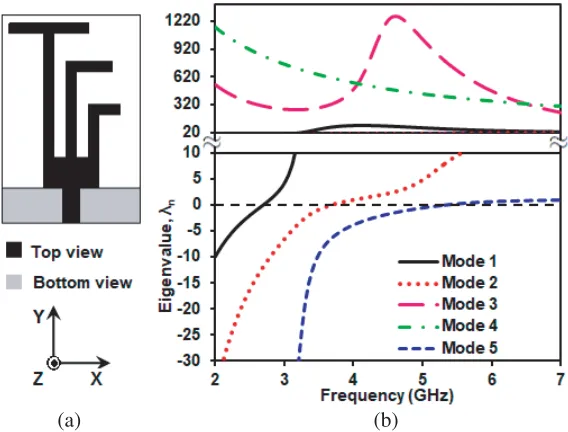
The CMA performance of the proposed multistubs loaded planar monopole antenna [34] is explored in this subsection. The configuration of antenna structure used for CMA is depicted in Fig. 1(a) and analyzed using multilayer solver of CST MWS. In multilayer solver, the radiating elements and ground plane are set to be PEC, and substrate material is set to be loss free. For CMA, there is no feed port used in the antenna structure.
(a) (b)
Figure 1. (a) Configuration of antenna used for CMA, and (b) predicted eigenvalues plot.
0 0.2 0.4 0.6 0.8 1
2 3 4 5 6 7
Modal signif
icance
Frequency (GHz)
Mode 1 Mode 2 Mode 3 Mode 4 Mode 5
Figure 2. Predicted modal significances plot of first five CMs for the proposed antenna.
90 120 150 180 210 240 270
2 3 4 5 6 7
Characteristi
c angle
(
o)
Frequency (GHz)
Mode 1 Mode 2 Mode 3 Mode 4 Mode 5
Figure 3. Predicted characteristic angles plot of first five CMs for the proposed antenna.
Figure 4. Predicted current distributions at excited CMs frequencies for the proposed antenna.
The predicted modal significance plot of the first five CMs for the proposed antenna structure is presented in Fig. 2. The resonance frequencies are determined by MSn= 1 for the nth mode, and the larger the MS value is, the more significant the mode is. The most significant modes (mode 1, 2, and 5) of an antenna structure are found to be 2.69, 3.68, and 5.35 GHz frequencies (where MS1,2,5 = 1), while mode 3 and 4 are insignificant (where MS3,4= 0). Moreover, the MS plot provides evidence that each significant CM contributes to radiate fields while insignificant CMs do not contribute to the radiated fields.
Further to analyse the CMs, the plot of predicted characteristic angles of the first five modes for the antenna structure is presented in Fig. 3. αn provide values ranging from 90◦ to 270◦ and are used to describe the CMs of the antenna structure. It is revealed that mode 1, mode 2, and mode 5 strongly resonate at 2.69, 3.68, and 5.35 GHz frequencies due toα1,2,5 = 180◦, while mode 3 and mode 4 do not resonate due to α3,4 = 90◦, which mainly store magnetic energy so that no resonance occurs.
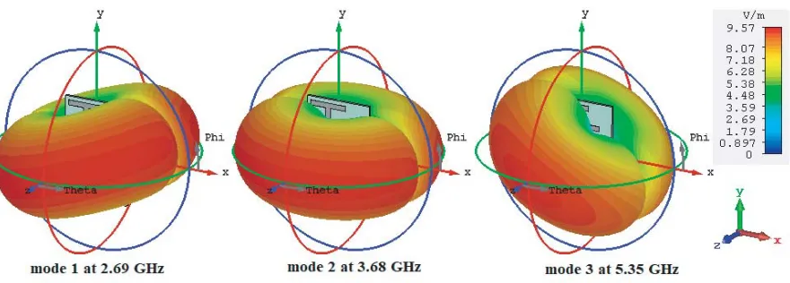
Figure 5. Predicted 3D fields at excited CMs frequencies for the proposed antenna.
(λg/4) due to presence of vertical current on the monopole. The predicted 3D field radiation of the antenna structure at excited CMs frequencies of 2.69, 3.68, and 5.35 GHz is presented in Fig. 5. As can be seen, all excited CMs have their maximal field in thexz-plane, and null occurs along they-axis. This shows that all CMs produce an omnidirectional pattern.
3. ANTENNA DESIGN AND ANALYSIS 3.1. Antenna Configuration
Figure 6(a) illustrates the configuration of the proposed multistubs loaded planar monopole antenna designed on a low loss Rogers RT/duroid 5880 dielectric substrate having dielectric constant (εr) 2.2, thickness 0.79 mm, and loss tangent 0.0009. The antenna is composed of a small rectangular patch Lp×Wp, a 50 Ω microstrip feed line of width Wf, a T-shaped stub resonator, inverted long and short L-shaped stub resonators with equal widths d = 1.5 mm on the front side and partial ground plane Lg×W on back side of substrate. Embedding three quarter guided wavelength (λg/4) stub resonators vertically (alongy-axis) with distinct gap ofg1 andg2 on upper contour of rectangular patch attributes to distinct triple resonances, much smaller size, and simple configuration. Overall size of the antenna
(a) (b)
is 20×30 mm2 (0.17λ0×0.26λ0, whereλ0 is the free space wavelength at 2.6 GHz).
Further to analyse the resonance modes of the proposed multistubs loaded monopole antenna, real (Re{Zin}) and imaginary (Im{Zin}) parts of the input impedance are plotted in Fig. 6(b). It can be observed that the oval regions I, II, and III exhibit fr1, fr2, and fr3 resonances of the antenna due to having almost 50 Ω real (resistance) with very low (i.e., almost zero) imaginary (reactance) part of impedance and produce resonances at about 2.60, 3.52, and 5.45 GHz, respectively. The optimized values of a planar structure after simulation on CST MWS are summarized in Table 1.
Table 1. Optimized parameters of the proposed multistubs loaded planar monopole antenna.
Parameter L Lp Lg L1 L2 L3 W Wp Wf W1 W2 W3 g1 g2
Value (mm) 30 4.5 5 17.8 12.3 6.15 20 8 2.44 5 5.3 4.5 1.7 1.8
3.2. Design Formulation for Multistubs Resonators
On the basis of the results of characteristics mode theory, we propose the subsequent design guidelines to excite three resonances in three steps for the multistubs resonators loaded antenna. The design formulation for the excitation of triple resonance modes (mode 1, 2, and 5) due to multistubs resonators and to compute the ith resonance frequency fri and effective dielectric constant εeff using Eqs. (4)
and (5) are as follows:
fri = c
4Lsi√εeff; i= 1,2,3 (4)
εeff ≈ εr+ 1
2 (5)
wherec= speed of light in vacuum (3×10⁸meter/second),εr = dielectric constant of the substrate, and Lsi = total length of the ith stub resonator responsible for resonance mode. For εr = 2.2, εeff = 1.60
by (5) is considered for computing the triple resonance frequencies.
Step 1: The firstfr1 frequency is excited due to one-fourth of guided wavelength of the T-shaped stub resonator, and it depends on the vertical arm lengthL1 and horizontal arm lengthW1as perceived current distributions from Fig. 4(a). The total length of T-shaped stub resonator forfr1(i= 1) can be computed by Eq. (6) with the help of following expression:
Ls1=L1+W1 ≈ λg
4 (6)
Step 2: The second fr2 frequency is excited due to one-fourth of guided wavelength inverted long L-shaped stub of vertical arm lengthL2 and horizontal arm lengthW2as perceived current distributions from Fig. 4(b). The total length of inverted long L-shaped stub for fr2(i = 2) can be computed by Eq. (7) with the help of following expression:
Ls2=L2+W2 ≈ λg
4 (7)
Step 3: The third fr3 frequency is excited due to one-fourth of guided wavelength inverted short L-shaped stub of vertical arm lengthL3 and horizontal arm lengthW3as perceived current distributions from Fig. 4(c). The total length of inverted short L-stub for fr3 (i= 3) can be computed by Eq. (8) with the help of subsequent expression:
Ls3=L3+W3 ≈ λg
4 (8)
3.3. Parametric Study of the Antenna
length of inverted long L-shaped stub L2, and vertical arm length of inverted short L-shaped stub L3 on the impedance bandwidth and resonances.
The bandwidth of the first resonance band is mainly affected by the vertical arm length L1 of T-shaped stub resonator. The impact of length L1 on the impedance bandwidth is shown in Fig. 7. It is observed that as length L1 increases, the first resonance mode frequency fr1 decreases, and there is no effect ofL1 on the secondfr2 and third fr3 frequencies. fr1 as a function of L1 is shown in Table 2. We see that thefr1calculated from Eq. (4) using Eqs. (5) and (6) agrees well with full-wave CST MWS simulation.
Table 2. First resonance mode frequency fr1 as a function ofL1.
L1,mm W1,mm Ls1,mm [Eq. (6)] fr1,GHz [Eq. (4)] fr1, GHz [CST MWS]
16.8 5 21.8 2.73 2.65
17.8 5 22.8 2.60 2.60
18.8 5 23.8 2.50 2.55
-40 -35 -30 -25 -20 -15 -10 -5 0
2 2.5 3 3.5 4 4.5 5 5.5 6 6.5 7 |S11
| (dB)
Frequency (GHz)
L1 = 16.8 mm
L1 = 17.8 mm
L1 = 18.8 mm
Figure 7. Effect of L1 on |S11| of the proposed multiband antenna.
-40 -35 -30 -25 -20 -15 -10 -5 0
2 2.5 3 3.5 4 4.5 5 5.5 6 6.5 7
|S11| (dB)
Frequency (GHz)
L2 = 11.8 mm L2 = 12.3 mm
L2 = 12.8 mm
Figure 8. Effect of L2 on |S11| of the proposed multiband antenna.
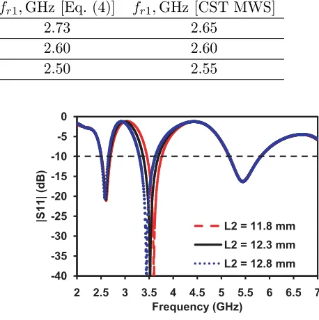
The bandwidth of the second resonance band is mainly affected by the vertical arm length L2 of inverted long L-shaped stub resonator. The impact of length L2 on the impedance bandwidth is displayed in Fig. 8. It is perceived that as lengthL2 increases, the second resonance mode frequencyfr2 decreases, and there is no effect of L2 on the firstfr1 and thirdfr3 frequencies. The fr2 as a function of L2 is shown in Table 3. We see that the fr2 calculated from Eq. (4) using Eqs. (5) and (7) agrees well with full-wave CST MWS simulation.
Table 3. Second resonance mode frequency fr2 as a function of L2.
L2,mm W2,mm Ls2,mm [Eq. (7)] fr2,GHz [Eq. (4)] fr2, GHz [CST MWS]
11.8 5.3 17.1 3.48 3.59
12.3 5.3 17.6 3.37 3.52
12.8 5.3 18.1 3.29 3.44
-40 -35 -30 -25 -20 -15 -10 -5 0
2 2.5 3 3.5 4 4.5 5 5.5 6 6.5 7
|S
11
| (dB)
Frequency (GHz)
L3 = 5.65 mm L3 = 6.15 mm L3 = 6.65 mm
Figure 9. Effect ofL3 on |S11|of the proposed multiband antenna. Table 4. Third resonance mode frequency fr3 as a function of L3.
L3,mm W3,mm Ls3,mm [Eq. (8)] fr3,GHz [Eq. (4)] fr3, GHz [CST MWS]
5.65 4.5 10.15 5.86 5.68
6.15 4.5 10.65 5.57 5.45
6.65 4.5 11.15 5.34 5.22
Table 5. Resonance frequencies obtained from different techniques used for the multiband antenna.
Calculated frequency (GHz)
Simulated TCM (GHz)
Simulated CST MWS (GHz)
Measured frequency (GHz)
2.60 2.69 2.60 2.55
3.37 3.68 3.52 3.42
5.57 5.35 5.45 5.50
shown in Table 4. We see that the fr3 calculated from Eq. (4) using Eqs. (5) and (8) agrees well with full-wave CST MWS simulation.
4. EXPERIMENTAL RESULTS AND DISCUSSION
The proposed optimized multiband antenna is fabricated on a Rogers RT/duroid 5880 substrate, and top and bottom views of the prototype are shown in Figs. 10(a) and (b), respectively. The reflection coefficient (|S11|) is measured on Agilent N5234A PNA-L network analyser for the validation of the simulated (|S11|) on CST MWS in open environment as displayed in Fig. 10(c). It resonates at 2.55/3.42/5.5 GHz frequencies with corresponding impedance bandwidths (IBWs) of 180 MHz (2.47–2.65 GHz)/360 MHz (3.27–3.63 GHz)/630 MHz (5.20–5.83 GHz) and FBWs of 7.03/10.43/11.4%, respectively. Comparison of resonance frequencies obtained from different techniques of the proposed multiband antenna is summarized in Table 5. We observe that the simulated resonance frequencies by TCM and CST MWS are nearly close to calculated and measured ones.
The automatic measurement setup used for radiation characteristics of the proposed multiband antenna in anechoic chamber is depicted in Fig. 11 along with zoomed view of the fabricated prototype. The broadband LB-10180 horn antenna (2–18 GHz) is used as reference antenna and developed fabricated prototype as the antenna under test (AUT) in an anechoic chamber.
(a) (b) (c)
Figure 10. Fabricated prototype (a) top view, (b) back view, and (c) simulated and measured|S11|of the proposed multiband antenna.
Figure 11. Measurement setup used for radiation characteristics of the proposed antenna.
0 1 2 3 4 5 6
2 2.5 3 3.5 4 4.5 5 5.5 6 6.5 7
Peak
gain (dBi)
Frequency (GHz)
Simulated Measured
Figure 12. Measured and simulated peak gain of the proposed antenna.
variation less than±0.35 dBi while the simulated gain 2.0–2.72, 1.96–2.58, and 1.94–2.62 dBi is achieved in 2.6 GHz, 3.5 GHz, and 5.5 GHz operating bands with gain variation less than ±0.4 dBi, respectively. Results support that the flat gain is achieved in the entire WiMAX/WLAN operating bands.
(a)
(b)
(c)
Figure 13. Measured and simulated radiation patterns at (a) fr1 = 2.55, (b) fr2 = 3.42, and (c) fr3 = 5.5 GHz frequencies.
can affect the measured radiation efficiency compared to simulated radiation efficiency.
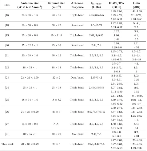
A performance comparison of previously reported related microstrip-fed/CPW-fed dual-/triple-band antennas with the proposed multidual-/triple-band antenna is summarized in Table 6. The antenna reported in [23] has small ground plane size of 22×2 mm2, yet it has dual-band functionality only. To the authors’ best knowledge, the proposed antenna is a step ahead that it has the smallest antenna volume (20×30 ×0.79 = 474 mm3), small ground plane size, very simple geometry to realize useable triple operating bands, and flat peak gain capability at all resonance frequencies as compared to other similar works reported in Table 6.
Table 6. Comparative study of the proposed antenna with previous microstrip-fed/CPW-fed dual-/triple-band antennas.
Ref. Antenna size
(W ×L×hmm3)
Ground size (mm2)
Antenna Response
fr1/r2/r3 (GHz)
IBWs/BW (GHz)
Gain (dBi)
[16] 23×38×1.6 23×16 Triple-band 2.45/3.5/5.5
2.28–2.56, 3.29–4.21, 5.05–5.91 1.48–1.96, 2.1–3.22, 2.63–3.56
[18] 50×50×0.8 50×22 Dual-band 1.54/5.73 1.22–1.89, 5.24–6.37
N.A., N.A.
[19] 25×30×0.8 25×11.5 Triple-band 2.61/4/5.85
0.22, 1.66, 1.48 3.5, 4.1, 5.5
[20] 25×32.5×1 25×10 Dual-band 2.44/5.8 0.08, 3.29–6.0
1.91, 4.53
[21] 30×38×1.6 30×12 Triple-band 2.5/3.5/5.5
2.35–2.72, 3.34–3.7, 4.81–6.74 1.5–2.7, 1.9–2.4, 3.4–4.9
[22] 18×33×1 18×13 Triple-band 2.6/3.4/5.5
2.5–2.7, 3.4–3.72, 5–6.8 −2, 1.5, 1
[23] 22×24×1.59 22×2 Dual-band 2.45/3.42 2.4–2.57, 3.3–3.61
3.02, 3.26
[24] 25×35×1 25×18 Triple-band 2.45/3.5/5.5
2.34–2.50, 3.07–3.82, 5.13–5.89 2.05, 2.6, 3.55
[25] 18×34×1.6 18×8.7 Triple-band 2.5/3.5/5.5
2.41–2.63, 3.39–3.70, 4.96–6.32
−0.1–0.28, 0.24–1.4,
2.6–4.7
[26] 24×30×0.79 24×5 Triple-band 2.62/3.47/5.42
2.50–2.71, 3.37–3.63, 5.20–5.85 1.33–2.52, 1.35–2.43, 1.25–2.62
[27] 73×60×0.8 N.A. Triple-band 3.5/4.5/5.8
3.47–3.51, 4.50–4.60, 5.75–5.81 1.1, 3.34, 5.1
[31] 40×45×1 40×30 Dual-band 2.44/5.5 2.3–4.0, 5.0–6.6
3.2, 2.34
This work 20×30×0.79 20×5 Triple-band 2.55/3.42/5.5
5. CONCLUSION
In this article, a simply structured low-profile miniaturized (0.17λ0 × 0.26λ0) multistubs loaded multiband antenna based on characteristic modes has been presented for WiMAX and WLAN applications. CMs analysis provides the guidance for excited electric and magnetic modes, feed position, and responsible parameter optimizations. The investigations and design formulation on the effect of multistubs resonators are carried out, and it has been considered to realize multiband antenna. A prototype has been fabricated and tested to demonstrate the validity of the proposed multiband antenna. The proposed antenna is best suited for 2.5/3.5/5.5 GHz WiMAX and 5.2/5.8 GHz WLAN applications.
ACKNOWLEDGMENT
The authors would like to acknowledge and convey their sincere thanks to Department of Electrical Engineering, Indian Institute of Technology, Kanpur, Uttar Pradesh, India and Government Mahila Engineering College, Ajmer, India for providing necessary facilities of measurement lab to complete this research work.
REFERENCES
1. Garbacz, R. J., “Modal expansions for resonance scattering phenomena,” Proc. IEEE, Vol. 53, No. 8, 856–864, 1965.
2. Harrington, R. F. and J. R. Mautz, “The theory of characteristic modes for conducting bodies,” IEEE Trans. Antennas Propag., Vol. 19, No. 5, 622–628, 1971.
3. Harrington, R. F. and J. R. Mautz, “Computation of characteristic modes for conducting bodies,” IEEE Trans. Antennas Propag., Vol. 19, No. 5, 629–639, 1971.
4. Chen, Y. and C.-F. Wang,Characteristic Modes: Theory and Applications in Antenna Engineering, John Wiley & Sons, Inc., Hoboken, New Jersey, 2015.
5. Cabedo-Fabres, M., E. Antonino-Daviu, A. Valero-Nogueira, and M. F. Bataller, “The theory of characteristic modes revisited: A contribution to the design of antennas for modern applications,” IEEE Antennas Propag. Mag., Vol. 49, No. 5, 52–68, 2007.
6. Yang, X., Y. Liu, and S.-X. Gong, “Design of a wideband omnidirectional antenna with characteristic mode analysis,” IEEE Antennas Wireless Propag. Lett., Vol. 17, No. 6, 993–997, 2018.
7. Zhao, X., S. P. Yeo, and L. C. Ong, “Planar UWB MIMO antenna with pattern diversity and isolation improvement for mobile platform based on the theory of characteristic modes,” IEEE Trans. Antennas Propag., Vol. 66, No. 1, 420–425, 2018.
8. Zhang, Q. and Y. Gao, “Compact low-profile UWB antenna with characteristic mode analysis for UHF TV white space devices,” IET Microw. Antennas Propag., Vol. 11, No. 11, 1629–1635, 2017. 9. Wu, W. and Y. P. Zhang, “Analysis of ultra-wideband printed planar quasi-monopole antennas using the theory of characteristic modes,” IEEE Trans. Antennas Propag. Mag., Vol. 52, No. 6, 67–77, 2010.
10. Tran, H. H., N. Nguyen-Trong, and A. M. Abbosh, “Simple design procedure of a broadband circularly polarized slot monopole antenna assisted by characteristic mode analysis,”IEEE Access, Vol. 6, 78386–78396, 2018.
11. Ghalib, A. and M. S. Sharawi, “New antenna mode generation based on theory of characteristic modes,”Int. J. RF Microw. Comput. Aided Eng., e21686, 2018, doi: 10.1002/mmce.21686.
12. Lu, W.-J. and L. Zhu, “Wideband stub-loaded slotline antennas under multi-mode resonance operation,” IEEE Trans. Antennas Propag., Vol. 63, No. 2, 818–823, 2015.
13. Zhang, X. Q., Y. C. Jiao, and W. H. Wang, “Compact wide tri-band slot antenna for WLAN/WiMAX applications,” Electron. Lett., Vol. 48, No. 2, 64–65, 2012.
15. Li, W.-M., B. Liu, and H.-Y. Zhao, “Parallel rectangular open slots structure in multiband printed antenna design,”IEEE Antennas Wireless Propag. Lett., Vol. 14, 1161–1164, 2015.
16. Xu, Y., C. Zhang, Y.-Z. Yin, and Z. Yang, “Compact triple-band monopole antenna with inverted-L slots and SRR for Winverted-LAN/WiMAX applications,”Progress In Electromagnetics Research Letters, Vol. 55, 1–6, 2015.
17. Liu, G., Y. Liu, and S. Gong, “Compact tri-band wide-slot monopole antenna with dual-ring resonator for WLAN/WiMAX applications,” Microw. Opt. Technol. Lett., Vol. 58, No. 5, 1097– 1101, 2016.
18. Liu, H.-W., F. Qin, J.-H. Lei, P. Wen, B.-P. Ren, and X. Xiao, “Dual-band microstrip-fed bow-tie antenna for GPS and WLAN application,”Microw. Opt. Technol. Lett., Vol. 56, No. 9, 2088–2091, 2014.
19. Lu, J.-H. and W.-C. Chou, “Planar dual U-shaped monopole antenna with multiband operation for IEEE 802.16e,” IEEE Antennas Wireless Propag. Lett., Vol. 9, 1006–1009, 2010.
20. Yang, X., Y.-Z. Yin, W. Hu, and K. Song, “Dual-band planar monopole antenna loaded with pair of edge resonators,” Electron. Lett., Vol. 46, No. 21, 1419–1421, 2010.
21. He, K., R.-X. Wang, Y.-F. Wang, and B.-H. Sun, “Compact tri-band claw-shaped monopole antenna for WLAN/WiMAX applications,” Journal of Electromagnetic Waves and Applications, Vol. 25, Nos. 5–6, 869–877, 2011.
22. Ellis, S. M., Z. Zhao, J. Wu, Z.-P. Nie, and Q. H. Liu, “A new compact microstrip-fed monopole antenna for triple band WLAN/WiMAX applications,” Progress In Electromagnetics Research Letters, Vol. 48, 129–135, 2014.
23. Naik, K. K., “Asymmetric CPW-fed SRR patch antenna for WLAN/WiMAX applications,” Int. J. Electron. Commun., Vol. 93, 103–108, 2018.
24. Xu, Y., Y.-C. Jiao, and Y.-C. Luan, “Compact CPW-fed printed monopole antenna with triple-band characteristics for WLAN/WiMAX applications,”Electron. Lett., Vol. 48, No. 24, 1519–1520, 2012.
25. Li, L., X. Zhang, X. Yin, and L. Zhou, “A compact triple-band printed monopole antenna for WLAN/WiMAX applications,” IEEE Antennas Wireless Propag. Lett., Vol. 15, 1853–1855, 2016. 26. Kumar, A., D. Jhanwar, and M. M. Sharma, “A compact printed multistubs loaded resonator
rectangular monopole antenna design for multiband wireless systems,”Int. J. RF Microw. Comput. Aided Eng., Vol. 27, No. 9, e21147, 2017.
27. Liu, H. W., H. Jiang, X. Guan, J. H. Lei, and S. Li, “Single-feed slotted bowtie antenna for triband applications,” IEEE Antennas Wireless Propag. Lett., Vol. 12, 1658–1661, 2013.
28. Hu, W., Y.-Z. Yin, X. Yang, and P. Fei, “Compact multiresonator-loaded planar antenna for multiband operation,”IEEE Trans. Antennas Propag., Vol. 61, No. 5, 2838–2841, 2013.
29. Mao, C.-X., S. Gao, Y. Wang, and B. Sanz-Izquierdo, “A novel multiband directional antenna for wireless communications,”IEEE Antennas Wireless Propag. Lett., Vol. 16, 1217–1220, 2017. 30. Weng, W.-C. and C.-L. Hung, “An H-fractal antenna for multiband applications,”IEEE Antennas
Wireless Propag. Lett., Vol. 13, 1705–1708, 2014.
31. Huang, H., Y. Liu, S. Zhang, and S. Gong, “Multiband metamaterial-loaded monopole antenna for WLAN/WiMAX applications,” IEEE Antennas Wireless Propag. Lett., Vol. 14, 662–665, 2015. 32. Boukarkar, A., X. Q. Lin, Y. Jiang, and Y. Q. Yu, “Miniaturized single-feed multiband patch
antennas,”IEEE Trans. Antennas Propag., Vol. 65, No. 2, 850–854, 2017.
33. Mark, R., N. Mishra, K. Mandal, P. P. Sarkar, and S. Das, “Hexagonal ring fractal antenna with dumb bell shaped defected ground structure for multiband wireless applications,”Int. J. Electron. Commun., Vol. 94, 42–50, 2018.