8
Satellite Image Processing Using Singular Value
Decomposition and Discrete Wavelet Transform
Kodhinayaki E
1, vinothkumar S
2, Karthikeyan T
3Department of ECE1, 2, 3, p.g scholar1, project coordinator2, guide3 Aksheyaa College of engineering1, 2, 3
Email:[email protected]
Abstract-To propose a new satellite image contrast enhancement technique based on the discrete wavelet
transform (DWT) and singular value decomposition (SVD). The technique DWT decomposes the input low contrast satellite image into four frequency sub bands referred to as low-low (LL), high-low (HL). Low-high (LH), high-high (HH) and estimates the singular value matrix of the low-low sub band image. The singular value matrix represents the intensity information of the given image and any change on the singular values change the intensity of the input image. After reconstructing the final image by using inverse dwt, the resultant image will not only be enhanced with respect to illumination but also will be sharper with good contrast. This technique is compared with conventional image equalization technique general histogram equalization (GHE) and state-of-the-art technique singular value equalization (SVE). The visual and quantitative results suggest that the proposed dwt and svd method clearly out performs the GHE and SVE method.
Index terms- contrast enhancement, discrete wavelet Transform (DWT), singular value decomposition.
1. INTRODUCTION
The aim of this project is to enhance the contrast
of the satellite image using Discrete Wavelet Transform (DWT) and Singular Value Decomposition (SVD). In these three techniques are discussed, DWT and SVD, GHE, SVE. While comparing these techniques, the visual and quantitative results suggest that the proposed DWT and SVD method clearly out performs the GHE and SVE method. One of the most important quality factors in satellite images comes from its contrast. Contrast enhancements frequently referred to as one of the most important issues in image processing. Contrast is created by the difference in luminance reflected from two adjacent surfaces. In visual perception, contrast is determined by the difference in the color and brightness therefore, we can perceive the world similarly regardless of the considerable changes in illumination conditions. If the contrast of an image is highly concentrated on a specific range, the information may be lost in those areas which are excessively and uniformly concentrated. The problem is to optimize the contrast of an image in order to represent all the information in the input image. There have been several techniques, such as general histogram equalization (GHE) and Singular Value Decomposition (SVE).9
method which is based on the singular-value decomposition of the LL sub band of the discrete wavelet transform (DWT). In spite of the improved contrast of the image, this method tends to distort image details in low- and high-intensity regions.
In remote sensing images, the common artifacts caused by existing contrast enhancement methods, such as drifting brightness, saturation, and distorted details; need to be minimized because pieces of important information are widespread throughout the image in the sense of both spatial locations and intensity levels. For this reason, enhancement algorithms for satellite images not only improve the contrast but also minimize pixel distortion in the low- and high-intensity regions. To achieve this goal, we present a novel contrast enhancement method for remote sensing images using dominant brightness level analysis s and adaptive intensity transformation. More specifically, the proposed contrast enhancement algorithm first performs the DWT to decompose the input image into a set of band-limited components, called HH, HL, LH, and LL sub bands. Because the LL sub band has the illumination information, the log-average luminance is computed in the LL sub band for computing the dominant brightness level of the input image. The LL sub band is decomposed into low-, middle-, and high-intensity layers according to the dominant brightness level. The adaptive intensity transfer function is computed in three decomposed layers using the dominant brightness level, the knee transfer function, and the gamma adjustment function.
2. SINGULAR VALUE DECOMPOSITION
In this paper, a novel technique based on the singular value decomposition (SVD) and discrete wavelet transform (DWT) has been proposed for enhancement of low-contrast satellite images. SVD technique is based on a theorem from linear algebra which says that a rectangular matrix A, that can be broken down into the product of three matrices, as follows: (i) an orthogonal matrix UA, (ii) a diagonal matrix ∑A and (iii)
the transpose of an orthogonal matrix VA. The singular- value-based image equalization (SVE) technique is based on equalizing the singular
Where UA and VA are orthogonal square matrices and ΣA matrix contains singular values on its main diagonal. Basic enhancement occurs due to scaling of singular values of the DCT coefficients. The singular value matrix represents the intensity information of input image and any change on the singular value of the generated normalized matrix, with mean zero and variance of one, over a particular image can be calculated using the equation as:
ξ = (∑ ( , ))
(∑ ) ………… (2)
By using this coefficient to regenerate an equalized image using used to remove the problem of the illumination.
Singular value decomposition (SVD) can be calculated mainly by the three mutually compatible points of view. On the one hand, we can view it as a method for transforming World Academy of Science, Engineering and Technology 55 2011 36 correlated variables into a set of uncorrelated ones that better expose the various relationships among the original data items. At the same time, SVD is a method for identifying and ordering the dimensions along which data points exhibit the most variation. This ties in to the third way of viewing SVD, which is that once we have identified where the most variation is present, then it is possible to find the best approximation of the original data points using fewer dimensions
10
space that exposes the substructure of the original data more clearly and orders it from most variation to the least.
fig.2(a)
Fig: 2(a) Lower and higher frequency distribution of an image (b) Zigzag (highest to lowest energy coefficients of DCT)
3. DISCRETE WAVELET TRANSFORM
The discrete wavelet transform which is based on the sub band coding is found to yield a fast computation of wavelet transform. It is easy to implement and reduces the computation time and resource required.
The foundations of DWT go back to 1976 when techniques to decompose discrete time signals were devised. Similar work was done in speech signal coding which was named as sub band coding.
In 1983, a technique similar to sub band coding was named pyramidal coding. Later many improvements were made to these coding schemes which resulted in efficient multi-resolution analysis schemes.
Fig. (a) Result of 2-D DWT
This operation results in four decomposed sub band images based on DWT referred to as low–
low (LL), low–high (LH), high–low (HL), and high–high (HH).
These techniques decompose the images into four frequency sub-bands by using DWT and estimate the singular value matrix of the low-low sub-band images.
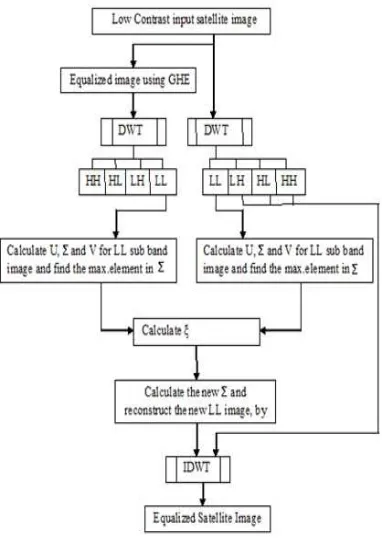
Fig3: Flow Chart for DWT-SVD
ALGORITHM
Step1: In the very first step, a low contrast input
satellite image has been taken for the analysis
Step2: Equalize the satellite image using general
histogram equalization technique.
Step3: After equalization, compute the discrete
wavelet transform for the contrast enhancement.
Step4: DWT of an image decomposed four sub
band images referred to as (LL, LH, HL, and HH)
Step5: calculate U, ∑ and V for LL sub band image
Step6: calculate ξ using the equation following
ξ =max (∑LLÂ)/max (∑LLA)
11
Step7: calculate the new ∑ and reconstruct the new LL image by using the IDWT
The LL image is composed by
∑͞LLA = ξ∑LLA LL͞A = ULLA ∑͞LLA VLLA
Now LL͞A, LHA, HLA and HHA sub band images of the original image are recombined by applying IDWT to generate the resultant equalized image
step8: equalized satellite image obtained .
(A̅ = IDWT LL̅A,LHA,HLA,HHA )
the proposed method has been used for enhancement of the several satellite images. Different satellite images are included to demonstrate the usefulness of this algorithm. The performance of this method is measured in terms of following significant parameters
Mean (µ) = ∑ ∑ ( , )
(σ) = ∑ ∑ { ( , )-µ)} 2
Mean (µ) is the average of all intensity value. It denotes average brightness of the image; whereas standard deviation (σ) is the deviation of the intensity values about mean. It denotes average contrast of the image. Here I(x, y) is the intensity value of the pixel (x, y), and (M, N) are the dimension of the image.
3.1 Enhancement of image
For performance evaluation, we used the measure of enhancement (EME), which is computed
EME = ∑ ∑ ( , )
( , ) ! ln
( , ) ( , ) !
Where k1k2 represents the total number of blocks in an image, Imax(k, l) represents the maximum value of the block, Imin(k, l) represents the minimum value of the block, and c represents a small constant to avoid dividing by zero.
4. RESULT
Experimental results demonstrate that the proposed
algorithm can enhance the low-contrast satellite images and is suitable for various imaging devices such as consumer camcorders, real-time 3-D reconstruction systems, and computational cameras.
(a)
(b)
(c)
(a) Low contrast original image for analysis (b) Equalized image by the GHE12
TABLE 1
MEAN AND STANDARD DEVIATION
Svd-dwt methods enhance gray scale images only and this method takes more processing time to enhance the low contrast satellite images. so, now propose FFT and bi-log transform to enhance the images
5
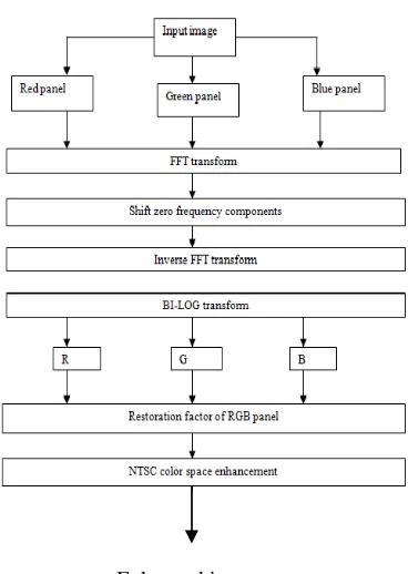
. FFT AND BI-LOG TRANSFORMWe propose a naturalness preserved enhancement algorithm for non-uniform illumination images. In general, we discuss three major issues, namely, the naturalness preservation, the intensity decomposition, and the illumination effect.
5.1 Fast Fourier transform
The Fourier Transform is an important image processing tool which is used to decompose an image into its sine and cosine components. The output of the transformation represents the image in the Fourier or frequency domain, while the input image is the spatial domain equivalent.
5.2 Bi-log transform
The intensity of the images log-shape histogram specification processed by histogram specification appears similar. In fact, the mapped illumination should look slightly different based on different intensity of input images. As can render the mapped illumination bright enough, we represent the difference by slightly increasing the pixels of low gray levels, according to the gray-level distribution of the input illumination.
5.3 Image enhancement
Increasing contrast is to apply an s-shaped curve to each of the RGB channels. One issue that arises is that the R G B ratio does not stay the same, resulting in saturation shifts (as well as hue shifts).
Enhanced image Fig. using FFT and bi-log
This is most visible as an overall increase in saturation. An algorithm that maintains the R G B ratio will not have such dramatic shifts in saturation.
6. CONCLUSION
In this paper, a new Satellite image contrast enhancement technique based on DWT and SVD has been proposed. This technique decomposed the input image into the DWT sub bands, and after updating the singular value matrix of the LL sub band, it reconstructed the image by using IDWT. The proposed technique was compared with GHE and SVE techniques for visual and quantitative performance evaluation. The quantitative results supports the visual results that the quality and information content of the equalized images are better preserved through the proposed DWT and SVD technique over GHE technique and SVE techniques.
FFT and bi-log transform enhance contrast as well as brightness better compared than svd-dwt method. And also enhance color images.
Input Image Mean (µ) & Standard Deviation (σ)
GHE Image Mean (µ) & Standard Deviation (σ)
DWT-SVD image Mean (µ) &
Standard Deviation (σ)
µ=162.018
σ=1.0767e+00
3
µ=114.854
σ=937.7782
µ=141.6760
σ=4.9526e+0
13
REFERENCES
1. E. Reinhard, M. Stark, P. Shirley, and J. Ferwerda, “Photographic tone reproduction for digital images,” in Proc. SIGGRAPH Annu.
Conf. Comput. Graph., Jul. 2002, pp. 249–
256.
2. H. Demirel, C. Ozcinar, and G. Anbarjafari, “Satellite image contrast enhancement using discrete wavelet transform and singular value decomposition,” IEEE Geosci. Reomte Sens.
Lett., vol. 7, no. 2, pp. 3333–337, Apr. 2010.
3. H. Demirel, G. Anbarjafari, and M. Jahromi, “Image equalization based on singular value decomposition,” in Proc. 23rd IEEE Int. Symp.
Comput. Inf. Sci., Istanbul, Turkey, Oct. 2008,
pp. 1–5.
4. L.Meylan and S. Susstrunk, “High dynamic range image rendering with a retinex-based adaptive filter,” IEEE Trans. Image Process., vol. 15, no. 9, pp. 2820–2830, Sep. 2006. 5. S. Chen and A. Beghdadi, “Nature rendering
of color image based on retinex,” in Proc.
IEEE Int. Conf. Image Process., Nov. 2009,
pp. 1813–1816.
6. S. Chen and A. Ramli, “Contrast enhancement using recursive mean separate histogram equalization for scalable brightness preservation,” IEEE Trans. Consum. Electron., vol. 49, no. 4, pp. 1301–1309, Nov. 2003. 7. S. Kim, W. Kang, E. Lee, and J. Paik,
“Wavelet-domain color image enhancement using filtered directional bases and frequency-adaptive shrinkage,” IEEE Trans. Consum.
Electron., vol. 56, no. 2, pp. 1063– 1070, May
2010.
8. S. Lee, “An efficient contrast-based image enhancement in the compressed domain using retinex theory,” IEEE Trans. Circuit Syst.
Video Technol.,vol. 17, no. 2, pp. 199–213,
Feb. 2007.
9. S. S. Agaian, B. Silver, and K. A. Panetta, “Transform coefficient histogram-based image enhancement algorithms using contrast entropy,”IEEE Trans. Image Process., vol. IP-16, no. 3, pp. 741–758, Mar. 2007.
10. T. Kim and J. Paik, “Adaptive contrast enhancement using gain controllable clipped histogram equalization,” IEEE Trans. Consum.
Electron., vol. 54, no. 4, pp. 1803–1810, Nov.
2008.
11. W. Ke, C. Chen, and C. Chiu, “BiTA/SWCE: Image enhancement with bilateral tone adjustment and saliency weighted contrast enhancement,” IEEE Trans. Circuit Syst.
Video Technol., vol. 21, no. 3, pp. 360–364,
Mar. 2010.