Installation & Operations Manual
NEC America, Inc.
NEC America reserves the right to change the specifications, functions, or features in this document at any time without notice. NEC America has prepared this document for use by its employees and customers. The information contained herein is the property of NEC America and shall not be reproduced without prior written approval from NEC America.
Copyright 1996
TABLE OF CONTENTS
Page
Chapter 1 - INTRODUCTION . . . 1
OVERVIEW. . . 1
MANUAL ORGANIZATION . . . 3
Chapter 2 . . . 3
Chapter 3 . . . 3
SCREEN ILLUSTRATIONS . . . 3
PROCEDURES . . . 5
GENERAL KEY USAGE . . . 5
REQUIREMENTS . . . 6
UAP Basic Configuration. . . 6
PBX Basic Configuration. . . 6
Chapter 2 - INSTALLATION INTRODUCTION . . . 7
Software Installation. . . 7
Application Configuration . . . 7
Tenant Database Configuration . . . 7
MAT Assignments . . . 7
Initialization / Termination . . . 7
SOFTWARE INSTALLATION . . . 9
STEP 1: Active CFC Application Check . . . 9
STEP 2: Existing CFC Installation Check . . . 9
STEP 3: Superuser (Root) Password . . . 10
STEP 4: MCS Enhancement or Independent APM Application . . . 10
STEP 5: CFC Directories and Database. . . 10
STEP 6: CFC Login Names . . . 11
STEP 7: CFC Auto-Config . . . 12
STEP 8: CFC Installation Processing (No input required.) . . . 13
STEP 9: CFC Installation Complete . . . 14
STEP 10: SCO UNIX Subsystem Database . . . 14
STEP 11: Reboot . . . 15
APPLICATION CONFIGURATION . . . 16
STEP 1: APPLICATION CHARACTERISTICS . . . 16
STEP 2: PRIMARY CONFIGURATION PARAMETERS . . . 17
STEP 3: FACILITIES . . . 18
STEP 4: OAI CONFIGURATION . . . 18
STEP 5: USER-DEFINED PARAMETERS . . . 19
MCI_SERVER. . . 20
STEP 1: APPLICATION CHARACTERISTICS . . . 20
STEP 2: PRIMARY CONFIGURATION PARAMETERS . . . 20
STEP 3: USER-DEFINED PARAMETERS . . . 21
TENANT DATABASE . . . 22
TENANT DATABASE RECORDS. . . 22
TENANT DATABASE EXAMPLES . . . 23
TENANT DATABASE CONFIGURATION . . . 23
STEP 1: BUILD THE MASTER DATABASE. . . 23
STEP 2: PROCESS THE APPLICATION DATABASE . . . 24
STEP 3: INSTALL THE APPLICATION DATABASE . . . 24
Page
INITIALIZATION/TERMINATION . . . 26
INITIALIZATION . . . 26
TERMINATION . . . 26
Chapter 3 - ADMINISTRATOR MAIN MENU INTRODUCTION. . . 27
STARTING THE CFC ADMINISTRATOR PROGRAM. . . 29
MAIN MENU OPTIONS . . . . 30
Extensions - . . . 30
Hard Forward Control - . . . . 30
Call Routing Control - . . . 30
Time Parameters - . . . 30
Special Events - . . . 30
Validate and Install - . . . 31
Quit - . . . 31
ASSIGNMENT WORKSHEETS . . . 31
EXTENSIONS. . . 34
OVERVIEW . . . 34
Procedure . . . 34
Commands . . . 34
Number of Extensions. . . . 34
Expanded Display . . . 35
ADD AN EXTENSION. . . 35
Procedure . . . 35
Field Entries . . . 36
DELETE AN EXTENSION . . . 36
Procedure . . . 36
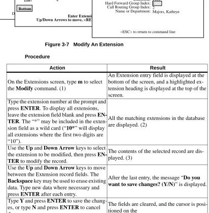
MODIFY AN EXTENSION . . . 37
Procedure . . . 37
Database Search . . . 38
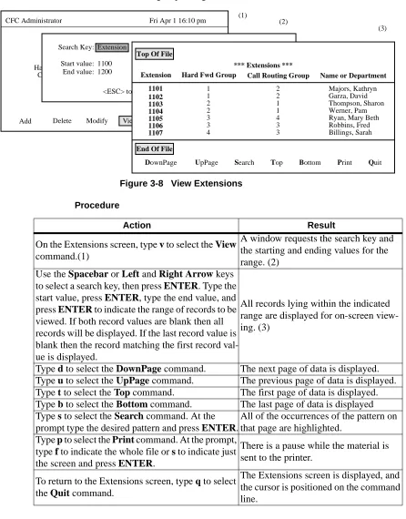
VIEW EXTENSIONS. . . 39
Procedure . . . 39
PRINT EXTENSIONS . . . 40
Procedure . . . 40
HARD FORWARD CONTROL . . . 41
OVERVIEW . . . 41
Procedure . . . 41
Groups - . . . 41
Patterns - . . . 41
Quit - . . . 42
HARD FORWARD GROUPS . . . 42
OVERVIEW . . . 42
Procedure . . . 42
Hard Forward Group Information . . . 42
Commands . . . 43
Expanded Display . . . 43
ADD A HARD FORWARD GROUP . . . 44
Procedure . . . 44
DELETE A HARD FORWARD GROUP . . . 45
Procedure . . . 45
Page
Procedure . . . 46
Database Search . . . 47
VIEW HARD FORWARD GROUPS . . . 48
Procedure . . . 48
PRINT HARD FORWARD GROUPS . . . 49
Procedure . . . 49
HARD FORWARD PATTERNS . . . 50
OVERVIEW . . . 50
Procedure . . . 50
Hard Forward Patterns Information. . . 50
Commands . . . 51
Expanded Display . . . 51
ADD A HARD FORWARD PATTERN. . . 52
Procedure . . . 53
DELETE A HARD FORWARD PATTERN . . . 54
Procedure . . . 54
. . . 54
MODIFY A HARD FORWARD PATTERN . . . 55
Procedure . . . 55
Database Search . . . 56
VIEW HARD FORWARD PATTERNS . . . 57
Procedure . . . 57
PRINT HARD FORWARD PATTERNS . . . 58
Procedure . . . 58
CALL ROUTING CONTROL. . . 59
OVERVIEW . . . 59
Procedure . . . 59
Monitored Numbers - . . . . 59
Groups - . . . 59
Patterns - . . . 60
Destinations - . . . 60
Quit - . . . 60
CALL ROUTING MONITORED NUMBERS . . . 61
OVERVIEW . . . 61
Procedure . . . 61
CALL ROUTING GROUPS. . . 62
OVERVIEW . . . 62
Procedure . . . 62
Call Routing Group Information. . . 62
Expanded Displays . . . 62
Commands . . . 63
ADD A CALL ROUTING GROUP . . . 64
Procedure . . . 64
DELETE A CALL ROUTING GROUP . . . 65
Procedure . . . 65
MODIFY A CALL ROUTING GROUP . . . 66
Procedure . . . 66
Database Search . . . 67
VIEW CALL ROUTING GROUPS. . . 68
Procedure . . . 68
Page
Procedure . . . 69
CALL ROUTING PATTERNS . . . 70
OVERVIEW . . . 70
Procedure . . . 70
Call Routing Pattern Information. . . 70
Expanded Display . . . 70
Movement Among Fields . . . 71
ADD A CALL ROUTING PATTERN . . . 72
Procedure . . . 72
DELETE A CALL ROUTING PATTERN . . . 73
Procedure . . . 73
MODIFY A CALL ROUTING PATTERN . . . 74
Procedure . . . 74
Database Search . . . 75
VIEW CALL ROUTING PATTERNS . . . 76
Procedure . . . 76
PRINT CALL ROUTING PATTERNS . . . 77
Procedure . . . 77
CALL ROUTING DESTINATIONS . . . 78
OVERVIEW . . . 78
Procedure . . . 78
Call Routing Destinations Information. . . 78
Expanded Display . . . 78
ADD A CALL ROUTING DESTINATION . . . 79
Procedure . . . 79
Non-Existent Data. . . 80
DELETE A CALL ROUTING DESTINATION . . . 81
Procedure . . . 81
MODIFY A CALL ROUTING DESTINATION . . . 82
Procedure . . . 82
Database Search . . . 83
VIEW CALL ROUTING DESTINATIONS . . . 84
Procedure . . . 84
PRINT CALL ROUTING DESTINATIONS . . . 85
Procedure . . . 85
TIME PARAMETERS . . . 86
OVERVIEW . . . 86
Procedure . . . 86
Time Parameters Information . . . 86
Time Formula . . . 86
Examples . . . 87
ADD A TIME PARAMETER . . . 88
Procedure . . . 88
DELETE A TIME PARAMETER . . . 89
Procedure . . . 89
MODIFY A TIME PARAMETER . . . 90
Procedure . . . 90
Database Search . . . 91
VIEW TIME PARAMETERS . . . 92
Procedure . . . 92
Page
Procedure . . . 93
SPECIAL EVENTS . . . 94
OVERVIEW . . . 94
Procedure . . . 94
Special Events Information . . . 94
ADD A SPECIAL EVENT . . . 95
Procedure . . . 95
Time Parameters. . . 96
Time Formula . . . 96
Examples . . . 96
MODIFY A SPECIAL EVENT . . . 97
Procedure . . . 97
MODIFY A SPECIAL EVENT’S TIME PARAMETERS . . . 98
Procedure . . . 98
MODIFY A SPECIAL EVENT’S HARD FORWARD GROUPS . . . 99
Procedure . . . 100
General Information . . . 100
MODIFY A SPECIAL EVENT’S CALL ROUTING GROUPS . . . 101
Procedure . . . 102
General Information . . . 102
DELETE A SPECIAL EVENT . . . 103
Procedure . . . 103
VIEW SPECIAL EVENTS . . . 104
Procedure . . . 104
PRINT SPECIAL EVENTS . . . 105
Procedure . . . 105
VALIDATE AND INSTALL . . . 106
OVERVIEW. . . 106
Procedure . . . 106
When to Use . . . 106
VALIDATE DATABASE. . . 107
Procedure . . . 107
Treatment of Discrepancies . . . 108
Possible Actions . . . 108
INSTALL DATABASE . . . 109
Procedure . . . 109
Validated Data . . . 110
LIST OF FIGURES
Figure Title Page
1-1 Call Forward Control System . . . 1
1-2 Main Menu with Screen Sections . . . 3
1-3 Screen Hierarchy and Movement . . . 4
1-4 Procedure Layout . . . 5
2-1 Installation Requirements . . . 8
3-1 CFC Administrator Main Menu . . . 29
3-2 Call Routing Control Assignment Worksheet . . . 32
3-3 Hard Forward Control Assignment Worksheet . . . 33
3-4 Extensions Option . . . 34
3-5 Add An Extension . . . 35
3-6 Delete An Extension . . . 36
3-7 Modify An Extension . . . 37
3-8 View Extensions . . . 39
3-9 Print Extensions . . . 40
3-10 Hard Forward Control Option . . . 41
3-11 Hard Forward Groups Option . . . 42
3-12 Add A Hard Forward Group. . . 44
3-13 Delete A Hard Forward Group. . . 45
3-14 Modify A Hard Forward Group . . . 46
3-15 View Hard Forward Groups. . . 48
3-16 Print Hard Forward Groups . . . 49
3-17 Hard Forward Patterns Option . . . 50
3-18 Add A Hard Forward Pattern . . . 52
3-19 Delete A Hard Forward Pattern . . . 54
3-20 Modify A Hard Forward Pattern. . . 55
3-21 View Hard Forward Patterns . . . 57
3-22 Print Hard Forward Patterns . . . 58
3-23 Call Routing Control Option. . . 59
3-24 Call Routing Monitored Numbers Option. . . 61
3-25 Call Routing Groups Option . . . 62
3-26 Add A Call Routing Group . . . 64
3-27 Delete A Call Routing Group . . . 65
3-28 Modify A Call Routing Group. . . 66
3-29 View Call Routing Groups . . . 68
3-30 Print Call Routing Groups . . . 69
3-31 Call Routing Patterns Option. . . 70
3-32 Add A Call Routing Pattern . . . 72
3-33 Delete A Call Routing Pattern . . . 73
3-34 Modify A Call Routing Pattern . . . 74
3-35 View Call Routing Patterns . . . 76
3-36 Print Call Routing Patterns . . . 77
3-37 Call Routing Destinations Option . . . 78
3-38 Add A Call Routing Destination . . . 79
Figure Title Page
3-40 Modify A Call Routing Destination. . . 82
3-41 View Call Routing Destinations . . . 84
3-42 Print Call Routing Destinations . . . 85
3-43 Time Parameters Option . . . 86
3-44 Add A Time Parameter . . . 88
3-45 Delete A Time Parameter . . . 89
3-46 Modify A Time Parameter . . . 90
3-47 View Time Parameters . . . 92
3-48 Print Time Parameters . . . 93
3-49 Special Events Option. . . 94
3-50 Add A Special Event . . . 95
3-51 Modify A Special Event . . . 97
3-52 Modify A Special Event’s Time Parameters . . . 98
3-53 Modify Special Event Hard Forward Groups . . . 99
3-54 Modify Special Event Call Routing Groups . . . 101
3-55 Delete A Special Event . . . 103
3-56 View Special Events . . . 104
3-57 Print Special Events . . . 105
3-58 Validate and Install . . . 106
3-59 Validate Database. . . 107
Chapter 1
INTRODUCTION
OVERVIEW
Call Forward Control (CFC) is an application suite that enhances the forwarding of incoming calls from both internal and external sources. The CFC programs use the Status Monitor, Switch Control, and Service Set facilities of the NEAX2400 IMS as accessed through the OAI. Telephones may be forwarded directly to an extension using the Hard Forward feature. Incoming calls received by an extension that has been forwarded to a monitored number may be routed to a specified destination using the Call Routing feature. Both Hard Forwarding and Call Routing can be controlled and tailored to suit the needs of the phone user based on time of day and/or day of week/year.
The CFC package consists of the following applications: • CFC Administration Program
• Call Routing Control Program (CRC) • Hard Forward Control Program (HFC)
CFC performs its call forwarding functions either within the Medical Center System (MCS) or as an independent application in the Applications Manager (APM) environment. Its communication with the NEAX PBX is based upon the NEC Open Application Interface (OAI). Figure 1-1 below illustrates the
relationship of these system components.
Figure 1-1 Call Forward Control System
NEAX PBX Internal
APM Password CFC
Incoming Hard Forward
Time
Validate, Call Routing
Special Medical Center
Extensions Extensions
Trunks
System (MCS) Menus
Administrator
Control Control Parameters
Events Process and Install
A B
Real-Time Call Rerouting
Menu-Driven Administration
Processes
OVERVIEW (Cont)
The CFC Administration program is used to create and modify the telephone databases and event schedules used by the HFC and CFC applications. Telephone extensions can be grouped by common forwarding (HFC) and routing (CRC) patterns. This grouping feature makes it possible to forward and/or reroute whole departments at a time or different departments according to different schedules or destination extensions. A Special Events table will allow Hard Forwarding and Call Routing groups to override their normal routing patterns temporarily during a specified time.
The Call Routing Control application runs in the background and performs the routing of monitored extensions using tables created by the CFC Administration application. CRC allows calls that originate internally to be routed differently than calls that originate externally. The CRC application requires the assignment of several monitored numbers, and phone users must forward their calls to these monitored numbers to activate Call Routing for their telephone. The monitored numbers will be associated with the call forwarding options available on the NEAX2400 and the Dterm phone. These forwarding options are:
• Forward all calls.
• Forward calls when line is busy. • Forward calls on no-answer.
Each forwarding option has a list of possible destinations. The first idle extension in the list is used as the routing destination. If all extensions are busy, then a default destination is used.
The Hard Forward Control application runs in the background and performs the direct forwarding of extensions to specific destinations at scheduled intervals using tables created by the CFC Administration application. Like the CRC application, HFC destinations may be specified for each of the NEAX 2400 forwarding options (all calls, busy, and no-answer). Unlike the CRC, HFC cannot route internal and external calls differently, and it only supports a single destination for each forwarding option. The HFC application may be used to forward phones
automatically to a monitored number used by CRC to provide automatic activation of Call Routing.
Briefly then, CFC makes it possible to:
• Assemble extensions into Hard Forward and Call Routing groups whose in-coming calls are forwarded and routed to the same destination(s).
• Implement different Hard Forward and Call Routing patterns at different times for the same group.
• Assign different Hard Forward and Call Routing patterns to different NEAX 2400 forwarding options (i.e., all calls, busy, no answer).
MANUAL ORGANIZATION
Chapter 2
Chapter 2 of this manual provides detailed information to be used in the software installation and configuration of Call Forwarding Control. The APM Operations Manual provides step-by-step instructions for entering the data that is presented in this chapter.
Chapter 3
This chapter describes the system of interrelated assignments that can be made through the CFC Administrator Main Menu. Each Main Menu option is described individually in a separate section in the chapter (e.g., Extensions, Groups, Forwarding Patterns, etc.). And each Main Menu option section contains subsections for the actions that can be taken with that option. For instance, extensions can be added, deleted, modified, viewed, or printed. So, within Section 3.1 Extensions, there is a separate subsection for each of these actions. This arrangement of subsections is true of most Main Menu options.
Each description contains an illustration of the screen(s) involved, information that is important to understand before making the assignment, and a step-by-step procedure for actually manipulating the CFC screens and functions. Because the assignments are very detailed and their relationships are important, an Assignment Worksheet, provided in the Main Menu Overview, makes it possible to plan and prepare the assignments before actually making them in CFC.
SCREEN ILLUSTRATIONS
The CFC screen contains the three basic sections that are shown below on the Main Menu and defined after the figure.
Figure 1-2 Main Menu with Screen Sections
CFC Administrator Fri Apr 1 16:10 pm
*** Main Menu ***
Extensions Hard Forward Control Call Routing Control Time Parameters Special Events Validate and Install Quit
Arrow keys to move cursor, <RET> to select, <ESC> to quit.
Main Working Area Heading or Title
SCREEN
ILLUSTRATIONS (Cont)
• Heading or TitleA display of the CFC name and a date and time stamp that is periodically updated.
• Main Working AreaThe area in which CFC menus are displayed, input is made to data entry prompts, and data is displayed for on-screen viewing. • Message / Command AreaThe bottom of the screen where instructions (e.g.,
Arrow keys to move cursor), commands (e.g., Add, Delete), and messages (e.g., extension must be unique.) are displayed.
The graphics in this manual illustrate both what is displayed on the terminal screens and the movement from one or more previous screens to the one under discussion. (See Figure 3)
Figure 1-3 Screen Hierarchy and Movement
CFC Administrator Fri Apr 1 16:10 pm
*** Main Menu ***
Hard Forward Control Call Routing Control Time Parameters Special Events Validate and Install Quit
Arrow keys to move cursor, <RET> to select, <ESC> to quit Extensions
CFC Administrator Fri Apr 1 16:10 pm
*** Extensions ***
Extension: Hard Forward Group Index: Call Routing Group Index:
Add Delete Modify View Print Quit
Name or Department:
CFC Administrator Fri Apr 1 16:10 pm
*** Extensions ***
Extension: Hard Forward Group Index: Call Routing Group Index:
SCREEN
ILLUSTRATIONS (Cont)
Each Section Overview displays graphically the movement from the Main Menu to the next screen level (i.e., Screen (1) to screen (2)). Thereafter, each subsection displays the movement from the second level screen to any third or fourth (i.e., Screen (2) to screen (3)). This progression of screens and the progression of subsections by Main Menu options makes it easier to stay in touch in the manual with the activity and position in the actual terminal screens.
PROCEDURES Each description includes a step-by-step set of instructions on how to select and move to the necessary screen and how to perform the possible actions. As shown below, the procedures are presented in a 2-column layout: The left column contains the action to be taken and the right, the results of having taken that action. Where there are field entries to be made on the screen, this manual provides field definitions in the right-hand column corresponding to the field name on the left.
Figure 1-4 Procedure Layout
GENERAL KEY USAGE
Throughout CFC, the following keys serve the purposes indicated for each: (Note: Clear notation is made wherever other key or key combinations apply or these do not.)
ENTER Accepts an indicated selection or field entry.
ESCGenerally exits the current screen or action to the most previous screen or action.
Arrow KeysMove the cursor in the direction indicated. If more than one screen full of items are displayed, press the DOWN arrow to scroll the list upwards and the UP arrow to scroll the list downwards.
Space BarSelects an option when more than one are available in a field; serves to toggle among scrolled or side-by-side options in a field.
BackspaceErases any data in a field.
Action Result
On the Extension menu, Press ENTER to select the Add command.(1)
The first field is highlighted for data entry. (2)
Enter data to the fields according to the defini-tions below, pressing ENTER after each
entry:
Extension - The extension number being added to the system; up to 5 digits in length; must be
assigned through the PBX MAT.
Group Index - The index to the group definition to which this extension is to be assigned; up to
3 digits in length.
After ENTER is pressed on the last field, the cursor returns to the command line.
To exit the data entry screen, enter q to select the Quit command.
GENERAL KEY USAGE (Cont)
Tab KeyPressed while in a field, displays information that corresponds to that field in other options. The following notation is includes in the description wherever this key can be used.
REQUIREMENTS Two groups of hardware are required for any OAI application: the User
Application Processor (UAP) and the Private Branch Exchange system (PBX). The minimum configuration for each of these groups is specified below.
UAP Basic Configuration
Requires a UAP 1000 or equivalent system
PBX Basic Configuration
• NEAX 2400 IMS with OAI compatible software • Release J4.80 or greater
• Interface Processor (IP) Unit (or OAI module). The specific hardware associated with the IP varies with the NEAX configuration -- IMG, MMG, UMG. Detailed lists of the hardware are provided in the OAI Module Installation Manual for the NEAX 2400 IMS.
Chapter 2
INSTALLATION INTRODUCTION
This chapter provides specific field entries that need to be made during the installation and configuration of Call Forward Control. In addition to this chapter, use instructions in the following manuals for this installation:
Applications Manager (APM) Installation Manual – Contains step-by-step instructions for installing the software from the release media.
Applications Manager (APM) Operations Manual – Explains how
applications like Call Forward Control are configured in the APM environment and how its databases are created, using the entries and values provided in this chapter.
NEAX2400 System Manuals – Give very detailed explanations about the assignments that need to be made through the Maintenance Administration Terminal (MAT) commands on the NEAX2400.
Briefly, the installation and set up of CFC involves the following sequence of steps, presented in this chapter as sections:
Software Installation
This section describes installation and configuration of the Call Forward Control software onto the User Application Processor from the release media.
Application Configuration
Call Forward Control is internally supported by the APM and must be configured in the APM environment. Call Forward Control is comprised of three internal components, all three of which must be configured. SECTION 2.2 of this chapter provides the information that must be entered into this APM configuration file. Use the instructions provided in the APM Operations Manual to make the entries contained in this section.
Tenant Database Configuration
The Call Forward Control applications use the Tenant Database, which is
configured using the APM. SECTION 2.3 of this chapter describes the creation and modification of the Tenant Database under the APM. Use the instructions provided in the APM Operations Manual to make the entries contained in this section.
MAT Assignments
There are data settings which must be assigned at the NEAX Maintenance Administration Terminal (MAT) before Call Forward Control can function. SECTION 2.4 specifies the necessary commands and the values at which they are to be set. Use the instructions provided in the NEAX2400 IMS System Manuals to make the entries contained in this section.
Initialization / Termination
The installation process, including its description in this manual and other manuals that are necessary, is illustrated in Figure 2-1.
Figure 2-1 Installation Requirements
Initialization / Termination APM Operations Manual NEAX 2400 IMS
Maintenance Administration Terminal (MAT) Assignments AMNO (Assignment of Monitored Numbers) AKYI (Assignment of Dterm Function Keys)
NEAX 2400 IMS System Manuals Application Configuration
Application Characteristics Primary Parameter Configuration
OAI Facilities (Optional) OAI Configuration Parameters (Optional)
User-Defined Parameters
APM Operations Manual Software Installation
Installationof Applications/Packages
CALL FORWARD CONTROL INSTALLATION REQUIREMENTS
APM Installation Manual
Tenant Database Configuration Define Database Fields Build Master Database Specify Application Database Fields
Process Application Database Install Application Database
SOFTWARE INSTALLATION
Installation of CFC software is initiated from the Applications Manager (APM) Platform Administration Main Menu. To display this menu, enter the login apmadm at the UNIX prompt and press ENTER. Using instructions in the APM Operations Manual, select and implement the Installation of Applications/ Packages option from this menu to load CFC software from release media. As the installation process executes, follow the steps described below as they correspond to the screen display and make input as directed. (Note: Necessary input is shown in boldface type.)
_____________________________________________
STEP 1: Active CFC Application Check
The first step performed during installation is to determine if any CFC applications are currently running on the system. If there are no active CFC programs, then installation continues with STEP 2. If CFC applications are running, then an error screen is displayed and installation is terminated. Use the APM to terminate all active CFC programs before attempting another CFC installation.
STEP 2: Existing CFC Installation Check
The next check performed during installation is to determine if a previous version of CFC is installed on the system. If CFC is not installed, then the Superuser (Root) Password screen is displayed as described in STEP 3. If CFC is installed, then a warning screen is displayed indicating that all CFC files will be saved in a backup directory if the installation is continued. Type y <ENTER> to continue or n <ENTER> to terminate.
The Call Forward Control Application is currently active. Installation cannot continue until Call Forward Control has been terminated through the Applications Manager.
Press Enter to continue. [ ] <ENTER>
WARNING: An existing CFC installation was detected on this system. If you continue with this installation, all existing CFC files will be saved in the /oai/app/cfc.s1 directory.
SOFTWARE INSTALLATION (Cont)
STEP 3: Superuser (Root) Password
Type the correct password for the root login and press <ENTER> to continue. An invalid password displays the message “Invalid root password. Do you wish to continue? (Y/N) [ ]”. Type y <ENTER> to try again, or n <ENTER> to cancel the installation.
STEP 4: MCS Enhancement or Independent APM Application
At this point in the installation, a search is made on the system to find the Medical Center software. If it is found, it is assumed that CFC is being installed to serve as an enhancement to the Medical Center System, and the screen in STEP 5 is displayed. If Medical Center software is not found, a status screen is displayed, indicating that if the installation is continued, CFC will be installed as an independent APM application. Type y <ENTER>
to continue or n <ENTER> to terminate.
STEP 5: CFC Directories and Database
The next step performed during installation is to create the necessary CFC directories. If a previous version of CFC is installed on the system, then a copy of the current database is saved. If the current database format is compatible with the new installation, the following status screen is displayed. Press the <ENTER> key
at the prompt to continue to the next step.
Super User (root) privileges are required.
Please enter the Super User Password: su/root password <ENTER>.
The CFC application can be installed as an extension of the Medical Center System or as an APM application. If you continue with this installation CFC will be installed as an APM application.
Do you wish to continue? (y/n) [y] <ENTER>
Creating CFC directories...
The existing /oai/app/cfc/data directory contains configuration information that is compatible with this version of the CFC. The /oai/app/cfc/data directory was left unchanged.
SOFTWARE INSTALLATION (Cont)
If the current database format is not compatible with the new installation, it is converted to the new database format and the following status screen is displayed. Press the
<ENTER> key at the prompt to continue to the next step.
If the database conversion fails, the following status screen is displayed. Press the
<ENTER> key at the prompt to continue to the next step.
If a previous version of CFC is not installed on the system, then the following screen is displayed. Press the <ENTER> key at the prompt to continue to the next step
STEP 6: CFC Login Names
The cfc and cfcadm login names are installed with the same user ID (default is 4010). Any change in the user ID value must be made for both login names since they both use the same user ID value. The following screen is displayed while installing the cfc user. Just press
ENTER at the user id prompt to accept the default value.
Creating CFC directories...
An existing /oai/app/cfc/data directory was found, and the contents will be saved in /oai/app/cfc.s1/data. A new /oai/app/cfc/data directory has been created, and the original database has been successfully converted. to the new data format and placed in the new directory. Press Enter to continue. [ ] <ENTER>
Creating CFC directories...
An existing /oai/app/cfc/data directory was found, and the contents will be saved in /oai/app/cfc.s1/data. A new /oai/app/cfc/data directory has been created, but the original database could not be converted to the new data format.
Press Enter to continue. [ ] <ENTER>
Creating CFC directories...
Press Enter to continue. [ ] <ENTER>
Installing cfc user on SCO UNIX Enter (cfc) user id [4010]: <ENTER> User (cfc) installed.
SOFTWARE INSTALLATION (Cont)
The following screen is displayed while installing the cfcadm user. Just press ENTER at the user id prompt to accept the default value. Note that a warning message is given when installing the cfcadm user, since it has the same user id as the cfc user. Enter y <ENTER> at the warning prompt and continue.
STEP 7: CFC Auto-Config
The installation script can load default HFC, CRC, and MCI_Server application configurations (see the Application Configuration section for additional details) if desired. The script will display the following screen:
Type n <ENTER> to skip the “auto-config” step, or y <ENTER> to load the default configurations. During the CRC configuration load the following screen is displayed:
At the prompt, type <ENTER> to continue.
Installing cfcadm user on SCO UNIX Enter (cfcadm) user id [4010]: <ENTER>
Warning: The user id [4010] is already assigned on this system. Install (cfcadm) with user id [4010]? (y/n) y <ENTER>
User (cfcadm) installed.
Press Enter to continue. [ ] <ENTER>
Would you like this script to ’auto-config’ the CFC applications into the APM Platform? You can skip applications within
’auto-config’ if already configured.
Enter Yes [y] to ’auto-config’. (y/n) [y] <ENTER>
/oai/utils/autocfg: running... /oai/utils/autocfg: CRC
SOFTWARE INSTALLATION (Cont)
During the HFC configuration load the following screen is displayed:
At the prompt, type <ENTER> to continue.
During the MCI_Server configuration load the following screen is displayed:
At the prompt, type <ENTER> to continue.
STEP 8: CFC Installation Processing (No input required.)
The installation script performs several tasks following the auto configuration and displays the results. Note that none of these actions require input. This process may include one or more of the following actions:
Installing the Tenant Database files.
Enter boot-up commands into UNIX boot-up sequence.
Install all remaining CFC files and directories as well as CFC host directories and executables.
Enter CFC crontab information.
Saving old CFC files from previous installations.
After these tasks have been completed, installation continues to the next step.
/oai/utils/autocfg: running... /oai/utils/autocfg: HFC
/oai/utils/autocfg: terminated normally Press any key to continue. <ENTER>
/oai/utils/autocfg: running... /oai/utils/autocfg: MCI_Server
SOFTWARE INSTALLATION (Cont)
STEP 9: CFC Installation Complete
When the installation script has completed the following screen is displayed.
Press <ENTER> to return the APM Administration Main Menu, then either exit the APM Administration program or use an Alt F(#) key combination to switch to another screen to perform Step 10.
STEP 10: SCO UNIX Subsystem Database
In this step, the SCO UNIX Subsystem Databases are updated to accept the new CFC information. Following this update, the passwords for the cfc and cfcadm login names are deleted, as follows:
At the SCO UNIX prompt, enter the superuser (root) and execute the SCO UNIX Subsystem Database authorization checking program (/tcb/bin/authck -s) and password deletion program (passwd -d) as shown below.
Answer yes when asked to fix the subsystem databases. This ensures that the SCO UNIX Subsystem Databases are left in a proper state. Deleting passwords for the cfc and cfcadm login names causes the system to ask for new passwords when first logging on using these names.
CFC Installation Complete
Press Enter to continue. [ ] <ENTER>
Sysname
Welcome to SCO System V/386 sysname!login: root
Password: <root password>
# /tcb/bin/authck -s
The following users have Protected Password Database entries that do not match their Subsystem Database entries:
cfc cfcadm
There are errors in the databases. Fix them (y/n)? y <ENTER>
# passwd -d cfc
Deleting password for user: cfc
Last Unsuccessful password change for cfc: Mon Mar 31 11:36:48 1997
# passwd -d cfcadm
SOFTWARE INSTALLATION (Cont)
If the MCI_Server component is used, two tty devices must be created in the SCO Subsystem database. This can be done by entering the SCO UNIX administration shell (sysadmsh), selecting Account –>Terminal –>Create and then creating each tty device (ttyn1a, ttyn1b, etc.). Refer to the SCO UNIX Administration Manual.
STEP 11: Reboot
When finished, the entire system should be rebooted. At the “#” prompt, enter the follow-ing command:
shutdown -g0 -i0 -y
When the message Safe to Power Off or Press Any Key to Reboot is displayed, reset the UAP by pressing a key and allowing it to reboot. Then continue with the installation.
This completes the loading of CFC software in the APM. Now go to Application
APPLICATION CONFIGURATION
If the “auto-config” utility was used during installation then default APM configuration data was loaded for the CRC, HFC, and MCI_Server applications. These default settings may require modification using the Select function of the Application Configuration option on the APM System Administration menu. If the “auto-config” utility was skipped, then the CRC, HFC, and MCI_Server
applications must be configured into the APM system using the Add function of the Application Configuration option on the APM System Administration menu.
–Enter the APM option from the APM Platform Management Menu. –Enter the System Administrator password at the APM password screen. –Enter the Application Configuration option from the System Administration menu.
–To add a new application type “A” and press <ENTER>. Fill out the configuration forms as described in the following steps.
–To modify an application installed by “auto-config” type “S” and press
<ENTER>. Use the arrow keys to select the desired application (HFC or CRC) and then press <ENTER>. Fill out the configuration forms as described in the following steps.
This section contains the information that should be entered to the configuration file for CRC and HFC. For specific instructions on what these parameters mean and how to make these entries, use the APM Operations Manual.
STEP 1: APPLICATION CHARACTERISTICS
When adding HFC and CRC configurations to the APM Application Configuration file, characterize, use the following values (if “auto-config” was used, these values are already set and cannot be changed):
Note: Entries for parameters that are marked with an asterisk (*) should be made exactly
as they are shown; all other entries in this section are the default values installed the “auto-config” utility and may be modified if necessary.
Parameter Entry Parameter Definition
OAI Application* Y Indicates whether or not (Yes or No) the application com-municates with the NEAX2400 using OAI processes.
CRT Application* N
Indicates whether or not (Yes or No) the application dis-plays on the same screen as the APM, rendering the APM
temporarily inaccessible.
APPLICATION CONFIGURATION (CONT)
STEP 2: PRIMARY CONFIGURATION PARAMETERS
On the APM Configuration Entry screen, make the entries shown below for CRC:
Make the entries shown below for HFC:
Parameter Entry Parameter Definition
Application Name CRC
Specifies the name to be displayed in the APM menus. This name is displayed however it is entered here; lower case letters and punctuation are acceptable; spaces are
not.
Executable Filename* /oai/app/cfc/
bin/CRC Defines the path name of the executable file. Group* CFC Names the group to which CRC is associated.
Response Mode* N(otify) Indicates the action that the APM is to take with CRC should a member of the group terminate.
Initialization Batch N(o) Indicates whether or not (Yes or No) CRC is to be initial-ized automatically when the OAI system is initialinitial-ized. Termination Mode* M(essage) Indicates how the APM is to notify CRC to terminate. Standard Output /dev/null Designates the file into which CRC output is redirected.
Number of Restarts 0 Indicates how many times the APM may restart CRC af-ter it af-terminates erroneously.
Parameter Entry Parameter Definition
Application Name HFC
Specifies the name to be displayed in the APM menus. This name is displayed however it is entered here; lower case letters and punctuation are acceptable; spaces are
not.
Executable Filename* /oai/app/cfc/
bin/HFC Defines the path name of the executable file. Group* CFC Names the group to which HFC is associated.
Response Mode* N(otify) Indicates the action that the APM is to take with HFC should a member of the group terminate.
Initialization Batch N(o) Indicates whether or not (Yes or No) HFC is to be initial-ized automatically when the OAI system is initialinitial-ized. Termination Mode* M(essage) Indicates how the APM is to notify HFC to terminate. Standard Output /dev/null Designates the file into which HFC output is redirected.
APPLICATION CONFIGURATION (CONT)
STEP 3: FACILITIES
According to instructions in the APM Operations Manual, designate the following NEAX2400 facilities for CRC using the Facilities command on the APM Configuration Entry screen:
SCF– Switch Control Facility
SMFN– Status Notification Facility
SMFR– Status Request Facility
Designate the following NEAX2400 facilities for HFC using the Facilities command on the APM Configuration Entry screen:
SSFM– Service Set Facility Monitor
SSFR– Service Set Facility Request
STEP 4: OAI CONFIGURATION
Using the OAI-Conf command on the APM Configuration Entry screen, make the entry shown for each of the following parameters for CRC and HFC: (Note: Make no entries to parameters that are not shown.)
Parameter Entry Parameter Definition
Tenant Number 1 Specifies the number of the tenant that the application
serves.
Source Link Name OAI1TCP
Identifies the port on the source side of the communication link; entry should correspond to a link name in the APM
system configuration file.
Destination Link
Name PBX1TCP
Identifies the port on the destination side of the communi-cation link; entry should correspond to a link name in the
APM system configuration file.
Association Recovery 30
Designates the number of seconds the application waits be-fore trying to re-establish an association with the NEAX
APPLICATION CONFIGURATION (CONT)
STEP 5: USER-DEFINED PARAMETERS
Make the entries below through the UserDefined command on the OAI Configuration screen for CRC:.
Make the following OAI Configuration entries for HFC:. U-D # Entry Parameter Definition
#1* /oai/app/cfc/
data/Names-File
Identifies the full path and filename of the file that contains the names of the databases used by CRC and listed on the CFC Administration Main Menu.
#2* MCI_Server If CRC is to forward calls to an existing on-site voice mail
system, indicates the name of the message center interface used to ensure correct delivery of calls to the voice mail box. If an on-site voice mail system exists and the MCI_Server
name is entered here, enter the MCI_Server configuration
informa-tion provided below to the APM Applicainforma-tion Configurainforma-tion f ile.
#3 3 Indicates the maximum number of times a call is forwarded before it is sent to the default extension that is designated for the group through the Main Menu.
#4 5 Indicates the number of seconds CRC waits before trying to deliver a call to voice mail after a previous attempt has failed. #5 0# Serves as a system default; that is, if all call forwarding
assignments in CRC were to fail, all calls are forwarded to this entry; must be the actual digits dialed, even to indicate the operator (0#).
U-D # Entry Parameter Definition #1* /oai/app/cfc/
data/Names-File
Identifies the full path and filename of the file that contains the names of the databases used by HFC and listed on the CFC Administration Main Menu.
#2* /oai/db/cur/ tenants
APPLICATION CONFIGURATION (CONT)
MCI_SERVER
If there is an existing on-site voice mail system with which CRC is to communicate, the MCI_Server application must be configured through the Application Configuration option
on the APM Administration Menu. The name MCI_Server must be entered as
User-Defined Parameter #2 in the CRC configuration (see Step 5 above). The information that should be entered to the configuration file for MCI_Server is shown below.
STEP 1: APPLICATION CHARACTERISTICS
Set the MCI_Server application characteristics as follows (if “auto-config” was used, these values are already set and cannot be changed):
STEP 2: PRIMARY CONFIGURATION PARAMETERS
Set the MCI_Server primary configuration parameters as follows:
Parameter Entry Parameter Definition
OAI Application* N Indicates whether or not (Yes or No) the application com-municates with the NEAX2400 using OAI processes.
CRT Application* N
Indicates whether or not (Yes or No) the application dis-plays on the same screen as the APM, rendering the APM
temporarily inaccessible.
Communication Queue* Y Indicates whether or not (Yes or No) the application needs an IPC queue to communicate with other processes.
Parameter Entry Parameter Definition
Application Name MCI_Server
Specifies the name to be displayed in the APM menus. This name is displayed however it is entered here; lower case letters and punctuation are acceptable; spaces are
not.
Executable Filename*
/oai/app/cfc/ bin/ MCI_Server
Defines the path name of the executable file.
Group* CFC Names the group to which MCI_Server is associated.
Response Mode* I(gnore) Indicates the action that the APM is to take with MCI_Server should a member of the group terminate.
Initialization Batch N(o)
Indicates whether or not (Yes or No) MCI_Server is to be initialized automatically when the OAI system is
initial-ized.
Termination Mode* M(essage) Indicates how the APM is to notify MCI_Server to termi-nate.
Standard Output /dev/null Designates the file into which MCI_Server output is re-directed.
Number of Restarts 0 Indicates how many times the APM may restart MCI_Server after it terminates erroneously. Communication
Queue 500
APPLICATION CONFIGURATION (CONT)
STEP 3: USER-DEFINED PARAMETERS
Make the entries below through the UserDefined command on the Configuration Entry screen:
This completes the configuration of Call Forward Control in the APM. Now go to the Tenant Database Section to set up the Tenant Database.
U-D # Entry Parameter Definition
#1 /dev/tty1a Identifies the UAP port used in the communication with the NEAX2400 IMS.
TENANT DATABASE
The Tenant Database is an APM database that is used by the HFC application and other OAI applications. It provides a mechanism for retrieving the tenant number of an extension. Since the Tenant Database may be used by other OAI Applications installed under the APM, it is configured using the APM and can not be modified by the Call Forward Control Administrator program.
TENANT DATABASE RECORDS
During CFC installation, the files tenant_m.mdf and tenants.adf are copied to the /oai/db/cur directory. The tenant_m.mdf file specifies the master database fields and contains the following definitions:
The tenants.adf file specifies the application database fields and contains the following definitions:
The Tenant Number field contains the Tenant Number that is used by one or more extensions. Tenant Numbers are associated with extensions using the following methods:
• A Tenant Number may be associated with a set of extensions defined by the First and Last Extension fields. The First Extension field contains the smallest extension number in the set, and the Last Extension field contains the largest extension number in the set.
• A Tenant Number may be associated with a single extension by setting the First and Last Extension fields to the same extension value.
• A Tenant Number may be associated with a single extension that contains a non-numeric character such as ’*’ or ’#’. The First Extension field contains the extension value, and the Last Extension field is left blank.
Field Description Type Size Minimum Value
Maximum Value First Extension ASCII 10
Last Extension ASCII 10
Tenant Number Numeric 3 1 255
Field Description Data Type First Extension ASCII
Last Extension ASCII
TENANT DATABASE EXAMPLES
The following examples display how the Tenant Database may be configured:
Example 1
All extensions use Tenant Number 1.
Example 2
Extensions 2000-2500 use Tenant Number 1. Extensions 1000-1500 use Tenant Number 2.
Extensions 1900, 2900, and 3900 use Tenant Number 3. Extensions “#68” and “*69” use Tenant Number 4. All other Extensions use Tenant Number 5.
TENANT DATABASE CONFIGURATION
The Tenant Database is configured using the Database Administration utilities provided by the APM. The following steps are required:
STEP 1: BUILD THE MASTER DATABASE
• From the APM System Administration menu, use the arrow keys to select the Database Administration command and press <ENTER>. The Database Administration menu is displayed.
• From the Database Administration menu, use the arrow keys to select the Build Master Database command and press <ENTER>. The Master File Selection menu is displayed.
• From the Master File Selection menu use the arrow keys to select the tenant_m database and press <ENTER>. The Database Entry menu is displayed.
First Extension Last Extension Tenant Number
0 99999 1
First Extension Last Extension Tenant Number
#68 4
*69 4
0 999 5
1000 1500 2
1501 1899 5
1900 1900 3
2000 2500 1
2501 2899 5
2900 2900 3
2901 3899 5
3900 3900 3
• Use the Add, Delete, and Modify commands to change the database. Use the Quit command when all changes have been made, answering ’Y’ when prompted “Do you want to save changes? (Y,N)”. The Master File Selection menu is displayed. At the Master File Selection menu press <ESC> to return to the Database Administration Menu.
STEP 2: PROCESS THE APPLICATION DATABASE
• At the Database Administration Menu use the arrow keys to select the Process Application Database command and press <ENTER>. The Process Application Database menu is displayed.
• From the Process Application Database menu use the arrow keys to select the tenant_m database and press <ENTER>.The APM will process the database, and the message “Database process operation complete” will be displayed. Press <ESC> to return to the Database Administration Menu.
STEP 3: INSTALL THE APPLICATION DATABASE
• At the Database Administration Menu use the arrow keys to select the Install Application Database command and press <ENTER>. The Install
Application Database menu is displayed.
• From the Install Application Database menu use the arrow keys to select the tenant_m database and press <ENTER>.The APM will install the database, and the message “Installing application database ’tenants’" will be
displayed. After the database is installed, the Database Administration Menu is displayed.
• At the Database Administration Menu use the arrow keys to select the Quit command and press <ENTER>. The APM System Administration menu is displayed.
MAT ASSIGNMENTS
This guide assumes that data settings that affect the operation of all OAI software on a system-wide basis have already been assigned on the NEAX Maintenance Administration Terminal (MAT). Such settings include, for instance, system index values and assignment of Interface I/O Port Data in the Interface Processor (IP).
For more information about these system data settings and for instructions in making the following Call Forward Control settings, consult the OAI Module Installation Manual for the NEAX2400 IMS.
AMNO Command (Assignment of Monitored Numbers): Whenever a call comes into a monitored number, CRC is informed and implements forwarding activity. Use this command to assign each number (forward busy, forward no answer, and forward all) to be monitored.
TN:Tenant to which the monitored number is assigned. MNO:The actual extension number that is to be monitored.
NMI:An unique and arbitrary number from 1 to 4000 assigned to the monitored number for internal use by the PBX. (Use LNMI to list indexes to determine which are available.)
UCD:A flag specifying the course of action to be taken with any call that is dialed into the monitored number when CRC is not operative, using the following values:
0 =(No) Call is not redirected to a UCD group, and caller hears re-order tone. 1 =(Yes) Call is redirected to a UCD group, which must then be specified.
AKYD Command (Assignment of Function Keys): Use this command to assign function keys on each Dterm that has previously been assigned through the ASDT command and is to be supported by CRC.
(Note: In making these assignments, the Dterm type must be indicated as Dterm.)
Station Number:Corresponds to one assigned through the ASDT Command. Dterm Type:Must be entered as Dterm.
Function Keys:Forward – all calls, Forward – busy, Forward – no answer
INITIALIZATION/TERMINATION
INITIALIZATION
The CRC and HFC applications must be initialized through the Non-CRT Application option on the APM Operations Menu according to instructions provided in the APM Operations Manual.
If an on-site voice mail system exists and the MCI_Server has been configured and named in the CRC configuration under User-Defined Parameter #2, MCI_Server must also be initialized from the Non-CRT Application option. CRC can perform its functions with or without MCI_Server, but CRC cannot communicate with a voice mail system without it.
Once the CRC, HFC, and optional MCI_Server applications are initialized, use an Alt F(#) key combination to switch to an unused screen, then enter the cfcadm at the system login prompt and press ENTER. The CFC Administrator Main Menu is displayed (refer to Chapter 3).
TERMINATION
Chapter 3
ADMINISTRATOR MAIN MENU INTRODUCTION
A brief discussion of how the CRC and HFC applications process calls will show how the Administrator Main Menu assignments fit together to equip CRC and HFC for the variety of rerouting tasks that it is capable of performing. Here are some examples:
Example 2: Hard Forward
The Engineering Department has a lunch hour from 12:00 noon to 1:00 p.m. Monday through Friday. During this time all calls received by members of this department will be handled by Pat the receptionist at extension 3470. HFC can automatically forward all engineering department telephones to Pat’s extension using the following settings:
All Engineering Department extensions are assigned to Hard Forward Group 1 (Engineering Department). Hard Forward Group 1 uses to Hard Forward Pattern 3, which specifies the following forwarding schedule:
Date and Time Destination Action
Mon-Fri, 12:00 noon 3470 Set
Mon–Fri, 1:00p.m. 3470 Cancel
At 12:00 noon Monday through Friday HFC will forward all extensions in Hard Forward Group 1 (Engineering Department) to extension 3470. At 1:00 p.m. Monday through Friday HFC will cancel the forwarding on all extensions in Hard Forward Group 1 (Engineering Department).
Example 1: Call Routing
At 9:00 Monday morning, Susan, who works in the Engineering Department, forwards her extension (3465) to the CRC monitored number 3995 so that she can attend a meeting. At 9:25 her phone receives a call from another internal extension. CRC detects the incoming call that has been forwarded from Susan’s extension. In response CRC checks its database for information about how to reroute calls to the Engineering Department and finds the following information:
Extension 3465 is assigned to Call Routing Group 1 (Engineering Department). Call Routing Group 1 uses Call Routing Pattern 3, which specifies the following routing schedule:
Date and Time Internal Destinations External Destinations Mon–Fri, 6:00 p.m. to 8 a.m. 2308, 2307, 2303, 2305 3300, 3301 Daily, 12:00 noon to 1:00 p.m. 2304, 2305, 2301, 2302 3400, 3401 Mon–Fri, 8:00a.m. to 5:00 p.m. 2300, 2301, 2302, 2303 3500, 3501 Sat & Sun, all day long 2300, 2301, 2302, 2303 3600, 3601
ADMINISTRATOR MAIN MENU INTRODUCTION (CONT)
The information which CRC and HFC use to manage the call forwarding processes described in previous examples is constructed through the CFC Administrator Main Menu options. Although it is not necessary to enter information through these Main Menu options in any particular sequence, the information must correspond from one option to another.
Example 3: Call Routing and Hard Forward
The Engineering Department has a lunch hour from 12:00 noon to 1:00 p.m. Monday through Friday. During this time all internal calls received by members of this department will be handled by receptionists at extensions 2304, 2305, 2301, and 2302. External calls will be handled by
receptionists at extensions 3400 and 3401. CRC and HFC together can accomplish these tasks using the following settings:
All Engineering Department extensions are assigned to Call Routing Group 1 (Engineering Department). Call Routing Group 1 uses Call Routing Pattern 3, which specifies the following routing schedule:
Date and Time Internal Destinations External Destinations Mon–Fri, 6:00 p.m. to 8 a.m. 2308, 2307, 2303, 2305 3300, 3301 Daily, 12:00 noon to 1:00 p.m. 2304, 2305, 2301, 2302 3400, 3401 Mon–Fri, 8:00a.m. to 5:00 p.m. 2300, 2301, 2302, 2303 3500, 3501 Sat & Sun, all day long 2300, 2301, 2302, 2303 3600, 3601
All Engineering Department extensions are also assigned to Hard Forward Group 1 (Engineering Department). Hard Forward Group 1 uses to Hard Forward Pattern 3, which specifies the following forwarding schedule:
Date and Time Destination Action
Mon-Fri, 12:00 noon 3995 Set
Mon–Fri, 1:00p.m. 3995 Cancel
STARTING THE CFC ADMINISTRATOR PROGRAM
The CFC Administrator program is started as described below:
Figure 3-1 CFC Administrator Main Menu
Action Result
At the UAP system console, press the Alt key and a function key (F1...F12) at the same time to select a
login screen
The UNIX login prompt is displayed
Type cfcadm at the UNIX prompt and press EN-TER. If prompted for a password, then type the
<password> and press ENTER.
The CFC Administrator Main Menu is displayed as shown in Figure 3-1.
Once inside the CFC menus, selection of an option or a command line function is made simply by typ-ing the highlighted key letter. It is not necessary to press
ENTER after making the selection. Also notice that the
key letter is not always the first letter of the menu option or command.
Refer to the following pages for information and instructions in the use of each option and
com-mand line function.
To exit the CFC Administrator Main Menu, type q
to select the Quit menu option.
The CFC Administrator Main Menu is cleared, and the cursor is positioned on the UNIX prompt.
CFC Administrator Fri Apr 1 16:10 pm
*** Main Menu ***
Extensions
Hard Forward Control Call Routing Control Time Parameters Special events Validate and Install Quit
MAIN MENU OPTIONS
The CFC Administrator Main Menu contains the following options:
Extensions
-Phone extensions supported by CRC and HFC are assembled into Call Routing and Hard Forward groups according to common needs. That is, if the phones in the Human Resources department are to be routed to the Operator at 5:00 p.m., all of these phones can be assembled into a Call Routing group which will route calls received by any phone in the group to the Operator after 5:00 p.m. Extensions can also be added to and deleted from the extensions database, they can be viewed on the display, or a hard copy can be printed. Each extension has a Call Routing and Hard Forward group index number which specifies the groups to which the extension belongs. One or both index values may be left blank to disable Call Routing and/or Hard Forwarding for an extension.
Hard Forward Control
-The Hard Forward Control option is used manipulate Hard Forward Control data. This option displays a sub-menu that contains Groups and Patterns options. Hard Forward groups and patterns may be created, deleted, modified, displayed, and printed using selections from this sub-menu.
Call Routing Control
-The Call Routing Control option is used manipulate Call Routing Control data. This option displays a sub-menu that contains Monitored Numbers, Groups, Patterns, and Destinations options. Call Routing groups, patterns, and destinations may be created, deleted, modified, displayed, and printed using selections from this sub-menu. Call Routing monitored numbers may also be set from this sub-menu.
Time Parameters
-Each Start Time Index identifies a schedule, or time frame, that is defined in hour, minute, month, and day detail. A time frame can be illustrated as “Daily at midnight”, “The first Monday of every month at 8:00 a.m., or “Monday through Friday, from 8:00 a.m. to 5:00 p.m.”. It is by these schedules that different Call Routing and Hard Forward patterns can be instituted for the same group at difference times. For instance, all of the phones in Accounting can be forwarded to the operator at noon every day, Monday through Friday, and to the Accounting receptionist console on Monday morning from 9:00 to 10:00 a.m.
Special Events
-There will occasionally be times during which the scheduled Call Routing and Hard Forward settings will need to be altered to accommodate holidays,
MAIN MENU OPTIONS (CONT)
Validate and Install
-CRC and HFC depend upon accurate correspondence among all of the assignments made through the CFC Administrator program. Thus, anytime a change is made to the information contained in one or more options, the Validate and Install option should be used to check compatibility of the new information with the existing information in other options and to process the changes so that CRC and HFC can implement them. Messages are displayed as necessary to notify the CFC
administrator of any errors or inconsistencies that are found during this checking and processing activity.
Quit
-The Quit option terminates the CFC Administrator program.
ASSIGNMENT WORKSHEETS
CALL ROUTING CONTROL ASSIGNMENT WORKSHEET
Group Name: ________________________________________________________________________________ Group Index:_________
Extension No. Name: Extension No. Name:
_____________ _________________________ _____________ _________________________ _____________ _________________________ _____________ _________________________ _____________ _________________________ _____________ _________________________ _____________ _________________________ _____________ _________________________ _____________ _________________________ _____________ _________________________ _____________ _________________________ _____________ _________________________ _____________ _________________________ _____________ _________________________ _____________ _________________________ _____________ _________________________
Default Destination: _____ Routing Pattern Index: ________
Internal Routing Patterns
Monitored Destination Start
No. Index Extensions Time Index Schedule
______ _____ _______________________________ _____ ___________________________ ______ _____ _______________________________ _____ ___________________________ ______ _____ _______________________________ _____ ___________________________ ______ _____ _______________________________ _____ ___________________________ ______ _____ _______________________________ _____ ___________________________ ______ _____ _______________________________ _____ ___________________________ ______ _____ _______________________________ _____ ___________________________ ______ _____ _______________________________ _____ ___________________________ ______ _____ _______________________________ _____ ___________________________ ______ _____ _______________________________ _____ ___________________________ ______ _____ _______________________________ _____ ___________________________
External Routing Patterns
Monitored Destination Start
No. Index Extensions Time Index Schedule
______ _____ _______________________________ _____ ___________________________ ______ _____ _______________________________ _____ ___________________________ ______ _____ _______________________________ _____ ___________________________ ______ _____ _______________________________ _____ ___________________________ ______ _____ _______________________________ _____ ___________________________ ______ _____ _______________________________ _____ ___________________________ ______ _____ _______________________________ _____ ___________________________ ______ _____ _______________________________ _____ ___________________________ ______ _____ _______________________________ _____ ___________________________ ______ _____ _______________________________ _____ ___________________________ ______ _____ _______________________________ _____ ___________________________
HARD FORWARD CONTROL ASSIGNMENT WORKSHEET
Group Name: __________________________________________________________________________________Group Index:_________
Extension No. Name: Extension No. Name:
_____________ _________________________ _____________ _________________________ _____________ _________________________ _____________ _________________________ _____________ _________________________ _____________ _________________________ _____________ _________________________ _____________ _________________________ _____________ _________________________ _____________ _________________________ _____________ _________________________ _____________ _________________________ _____________ _________________________ _____________ _________________________ _____________ _________________________ _____________ _________________________
Default Destination: _____ Forward Pattern Index: ________
Forward Busy Patterns
Destination Start Time Destination Start Time
Index Extension Index Action Index Extension Index Action
_____ __________ _____ ___________ _____ __________ _____ ____________ _____ __________ _____ ___________ _____ __________ _____ ____________ _____ __________ _____ ___________ _____ __________ _____ ____________ _____ __________ _____ ___________ _____ __________ _____ ____________ _____ __________ _____ ___________ _____ __________ _____ ____________ _____ __________ _____ ___________ _____ __________ _____ ____________
Forward No Answer Patterns
Destination Start Time Destination Start Time
Index Extension Index Action Index Extension Index Action
_____ __________ _____ ___________ _____ __________ _____ ____________ _____ __________ _____ ___________ _____ __________ _____ ____________ _____ __________ _____ ___________ _____ __________ _____ ____________ _____ __________ _____ ___________ _____ __________ _____ ____________ _____ __________ _____ ___________ _____ __________ _____ ____________ _____ __________ _____ ___________ _____ __________ _____ ____________
Forward All Calls Patterns
Destination Start Time Destination Start Time
Index Extension Index Action Index Extension Index Action
_____ __________ _____ ___________ _____ __________ _____ ____________ _____ __________ _____ ___________ _____ __________ _____ ____________ _____ __________ _____ ___________ _____ __________ _____ ____________ _____ __________ _____ ___________ _____ __________ _____ ____________ _____ __________ _____ ___________ _____ __________ _____ ____________ _____ __________ _____ ___________ _____ __________ _____ ____________