Simulation of SRF Based DSTATCOM With Grid
Connected PV Generation System Using Fuzzy
Logic Controller For Reactive Power Management
R. Deepak Singh1, T. Praveen Kumar2, Dr.K.Sumanth3
PG Research Scholar, Dept. of EEE, Sreenidhi Institute of Science and Technology, Hyderabad, Telangana, India1 Associate Professor, Dept. of EEE, Sreenidhi Institute of Science and Technology, Hyderabad, Telangana, India2 Professor & Principal, Dept. of EEE, Sreenidhi Institute of Science and Technology, Hyderabad, Telangana, India3
ABSTRACT: Due to extensive use of automatic and power electronic based devices in an electric distribution system, power quality problems have been substantially increased. Distribution system has poor power quality due to insufficient reactive power during steady and dynamic state. DSTATCOM is promising shunt connected custom power device for mitigating the power quality issues. In this paper investigation of SRF based DSTATCOM with grid connected PV generation system using fuzzy logic controller over PI controller is elaborated for reactive power management and is simulated using simpowersystem block sets of MATLAB. PV generation system is interfaced with the grid through boost converter and two level voltage source converter, SRF based theory is implemented for control of DSTATCOM in UPF mode of operation. The simulation results shows that fuzzy logic control provides better system response and reactive power control over PI controller.
KEYWORDS: PV Generating System,DC-DC Boost converter, SRF Theory, DSTATCOM, PI Controller, Fuzzy Logic Controller
I.INTRODUCTION
for VSC. For maintaining constant and stabilised voltage across capacitor a PI controller is used. To certain extent PI controller works satisfactorily and give better results, but for dynamic and highly non linear loads the stability of the system hampers. In place of PI controller a fuzzy controller is used in this paper and its performance is investigated. Also for operating DC-DC boost converter pulses are generated by PWM technique. In this paper simulation of SRF based DSTATCOM with grid connected PV generation system using fuzzy logic controller for reactive power management over PI controller is investigated. The comparative results are analysed and found that fuzzy logic controller gives better response compared to PI controller over study and dynamic states.
II.SYSTEM CONFIGURATION
Fig.1 shows the schematic diagram of grid interfaced 20kW solar PV power generating system through boost DC-DC converter and two level VSC based DSTATCOM used for implementing/simulating the proposed scheme in MATLAB/simulink environment using simpowersystem block sets.
Fig.1 Schematic diagram of grid interfaced solar PV power generating system through boost DC-DC converter and two-level VSC based DSTATCOM
The design and selection criteria involved for development of the entire system components such as solar photovoltaic generation, DC-DC boost converter, interfacing inductors, DC link capacitor and the ripple filter are described below [10]-[11]
A. Design of the Solar Photovoltaic generation
The SPV power generating system is designed for a 20kW peak power capacity. According to design considerations 14 modules in series 10 modules in parallel, one solar module consists of 40 cells in series. Each cell has an open circuit voltage ( ) 0.64 V and short circuit current ( ) of 3.7A.
B. Design of DC-DC Boost Converter
The DC-DC boost converter is shown in Fig.1. The voltage from PV cell is boosted by using DC-DC boost converter to 700V. The design parameters of the DC-DC boost converter are given as.
where D is duty cycle (D) = 1-( / ). This converter boosts the voltage of SPV array from = = 360 V to =700 V. The calculated value of D is 0.485 and = is output voltage from PV array. ∆ is input current ripple and for this converter design, the value of ∆ is considered 10% of input current, f is switching frequency and the value of = 10 kHz. The value of inductance ( ) from Eq. (1) is obtained as 1.5 mH.
C. Selection of DC link Capacitor
The output capacitor for this DC-DC boost converter shown in Fig.1 is given as
=
∗(∆ ∗ )
... (2)
where = ( / ) is the output current. is the output power of the DC-DC boost converter and ΔV is peak ripple in output voltage. is output voltage, the value of this ΔV is taken 3% of and value of output current ( ) is calculated as 31.25 A. The value of output capacitor ( ) from (2) is calculated as 700µF.
D. Selection of DC reference voltage
The minimum dc bus voltage of VSC should be greater than twice the peak of phase voltage of the system as,
=
√ ∗√ ... (3)
The dc bus voltage is calculated as is the ac line output voltage of VSC. Thus, is obtained from Eq. (2) as 677.69 V for of 415 V and it is selected as 700 V.
E. Selection of interfacing Inductor
The design of AC inductance ( ) of VSC is given as,
=
√ ∗ ∗( ∗ ∗ ∗∆ ) ... (4)
where ∆I is current ripple and its value is 5%, switching frequency and its value is 10 kHz, ( ) dc bus voltage and its value of is 700V, m is the modulation index and its value is 0.9, h is the overload factor and its value is given as 1.2. The calculated of is 4.97 mH. A round-off value of of 5 mH is selected.
III.CONTROL ALGORITHM
Fig.2 Schematic diagram of SRF based control algorithm for extracting reference source currents
The control approach used for estimation of reference currents for the control of VSC in a synchronous reference frame theory (SRFT) is described below. The SRF theory is based on the transformation of the load currents in synchronously rotating d-q frame. This control system is shown in Fig. 2 load currents ( , , ), PCC voltages ( , , ) and DC bus voltage ( ) of VSC are sensed as feedback signals. Load currents in the three phases are converted to dq0 frame using following transformations,
=
⎣ ⎢ ⎢ ⎢
⎡ cos −sin
cos − −sin −
cos + sin + ⎦⎥
⎥ ⎥ ⎤
... (5)
A three phase PLL (phase locked loop) is used to synchronize these signals with the PCC voltage. These d-q current components are then passed through a LPF to extract the DC component of & . The d-axis and q-axis currents consist of fundamental and harmonic components as
= + ... (6) = + ... (7)
A SRF controller extracts DC quantities by LPF and hence the non-DC quantities are separated from reference signals.
Control of Proposed System for Unity Power Factor
The control strategy for reactive power compensation for UPF mode of operation considers that the supply must deliver the dc component of direct-axis component of load current( ) along with the active power component for maintaining the dc bus meeting the losses ( ). The dc link voltage of the VSC is maintained at a predetermined voltage level using a PI controller. This facilitates active power transfer from the PV array and determination of VSC losses. The PI controller generates a compensating current signal as,
= ( −1) + { ( )− ( −1)} + ( ) ... (8)
where ( ) = ∗ ( )− ( ) is the error between the reference ( ∗ ) and sensed ( ) DC voltage at the nth sampling instant and , are the proportional and integral gain constant of the DC bus voltage PI controller
Therefore, the reference direct-axis supply current is
reverse Park’s transformation as
∗ ∗ ∗
=
cos sin 1
cos( − ) sin( − ) 1 cos( + ) sin( + ) 1
∗ ∗ ∗
... (10)
Current-Controlled Pulse width Modulation (PWM) Generator
In a current controller, the sensed and reference source currents are compared and a proportional controller is used for amplifying current error in each phase before comparing with a triangular carrier signal to generate the gating signals for six IGBT switches of VSC of DSTATCOM.
V. FUZZY CONGIC CONTROLLER
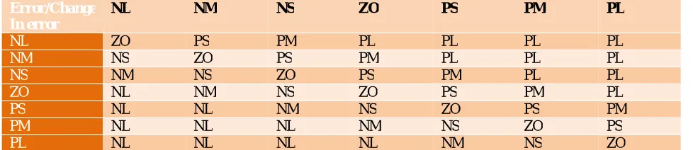
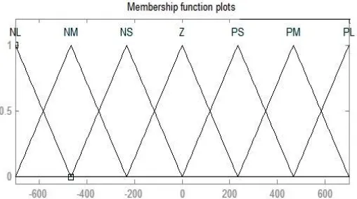
A fuzzy logic controller (FLC) consists of four elements, which are a fuzzification interface, a rule base, an inference mechanism, and a defuzzification interface. A FLC is designed for voltage regulation of DC bus. The design of the FLC for DC voltage regulator is described in detail [13]. The design of the fuzzy controllers for the AC and current regulators follows similar procedure. FLC designed for DC voltage regulator has two inputs and one output. The error e(t) (e = − ) and the rate of change of error ∗(t) the inputs and the output of the FLC is Δ . In fact, Δ is integrated to produce . Fig.3 shows schematic diagram for implementation of FLC for DC voltage regulation across DC link capacitor where GE, GCE, and GCU are the scaling factors for the inputs and output respectively given in appendix. The linguistic variables for error e(t), the rate of change of error ∗(t) and the controller output Δ will take on the following linguistic values: NL = Negative Large; NM = Negative Medium; NS = Negative Small; ZO = Zero; PS = Positive Small; PM= Positive Medium; PL = Positive Large.
Fig.3 Schematic diagram for implementation of FLC
The above linguistic quantification has been used in this paper to specify a set of rules or a rule-base. The rules are formulated from practical experience. For the FLC with two inputs and seven linguistic values for each input, there are 72 = 49 possible rules with all combination for the inputs [14]-[15]. The tabular representation of the FLC rule base (with 49 rules) of the fuzzy control based DC voltage regulator is shown in Table 1:
TABLE 1: 7 × 7 FLC RULE - BASE IN TABULAR FORM
Error/Change In error
NL NM NS ZO PS PM PL
NL ZO PS PM PL PL PL PL
NM NS ZO PS PM PL PL PL
NS NM NS ZO PS PM PL PL
ZO NL NM NS ZO PS PM PL
PS NL NL NM NS ZO PS PM
PM NL NL NL NM NS ZO PS
PL NL NL NL NL NM NS ZO
Fig. 4 Membership functions considered for scaling input error e (t) Fig. 5 Membership functions considered for scaling the rate of change of error ȇ (t)
Fig. 6 Membership functions considered for scaling the output.
VI. RESULTS
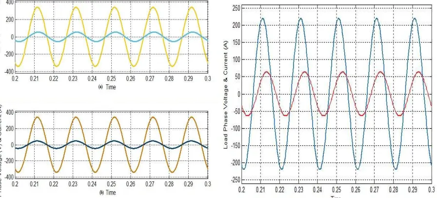
Fig.7 (a) & (b) Source Phase Voltage & Current Relation with fuzzy& PI Controlled DSTATCOM Fig.7(c) Load Phase Voltage and Current Relation without DSTATCOM
Fig. 8 (a) Reactive power flow in the system with DSTATCOM using PI controller Fig.8 (b) Reactive power flow in the system with DSTATCOM using fuzzy logic controller
Fig. 10 (a) Source Phase Voltage and Current Relation of Dynamic loads with Fuzzy controlled DSTATCOM Fig.10 (b) Load Phase Voltage and Current Relation of Dynamic loads without DSTATCOM
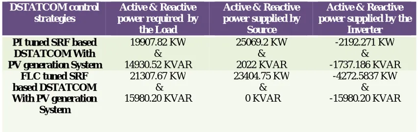
TABLE 2: Active and reactive power comparisions of SRF based DSTATCOM with grid connected PV generation system using PI & fuzzy logic controller for reactive power management
DSTATCOM control strategies
Active & Reactive power required by
the Load
Active & Reactive power supplied by
Source
Active & Reactive power supplied by the
Inverter
PI tuned SRF based DSTATCOM With PV generation System
19907.82 KW & 14930.52 KVAR
25069.2 KW & 2022 KVAR
-2192.271 KW & -1737.186 KVAR
FLC tuned SRF based DSTATCOM With PV generation
System
21307.67 KW & 15980.20 KVAR
23404.75 KW & 0 KVAR
-4272.5837 KW & -15980.20 KVAR
VII. SUMMARY AND CONCLUSIONS
APPENDIX
Simulation Data
REFERENCES
REFERENCES
[1] Reactive power Management by D.M. Tagare, Tata McGraw Hill, 2004.
[2] Afshin Izadian, Arash Pourtaherian, and Sarasadat Motahari,“Basic Model and Governing Equation of Solar Cells used in Power and Control Applications” Conference: Energy Conversion Congress and Exposition (ECCE), 2012 IEEE, DOI:10.1109/ECCE.2012.6342639
[3] Hiren Patel and Vivek Agarwal, “MATLAB-Based Modeling to Study the Effects of Partial Shading on PV Array Characteristics” IEEE Transactions On Energy Conversion, Vol. 23, No. 1, March 2008.
[4] D.Shmilovitz, “Photovoltaic Maximum Power Point Tracking Employing Load Parameters” IEEE ISIE 2005, June 20-23, 2005.
[5] N. Pandiarajan and Ranganath Muthu, “Mathematical Modeling of Photovoltaic Module with Simulink” International Conference on Electrical Energy Systems (ICEES 2011), 3-5 Jan 2011.
[6] Williams K. Francis1, Prof. Shanifa Beevi S, Prof. Johnson Mathew, “MATLAB/Simulink PV Module Model of P&O And DC Link CDC MPPT Algorithms with Lab view Real Time Monitoring And Control Over P&O Technique” International Journal of Advanced Research in Electrical, Electronics and Instrumentation Engineering, Vol. 3, Special Issue 5, December 2014, ISSN (Print): 2320 – 3765.
[7] P. Bapaiah, “Power Quality Improvement by using DSTATCOM”, International Journal of Emerging Trends in Electrical and Electronics (IJETEE), Vol. 2, Issue. 4, April-2013
[8] Bhim singh, Ambrish Chandra, Kamal-al-haddad, “Power Quality Problems and mitigation Techniques”, Wiley publications, 2015. [9] Arun Kumar, Verma, Bhim Singh, & D.T Shahani, “Grid Interfaced Solar Photovoltaic Power Generating System with Power Quality
Improvement at AC Mains” IEEE ICSET 2012, Nepal.
[10] Mohammed S. Ibbini, Shadi Mansi , Mohammed Masadeh , Eid Al Hajri, “Simscape Solar Cells Model Analysis and Design” Computer Applications in Environmental Sciences and Renewable Energy, ISBN: 978-960-474-370-4.
[11] Arun Kumar, Verma, Bhim Singh, & D.T Shahani, “PBT Based Control of Grid Interfaced Solar Photovoltaic Power Generating System with Improved Power Quality”,IEEE Conference on Power Electronics, Drives and Energy Systems Dec 16-19, 2012, Bengaluru, India.
[12] Bhim Singh & Jitendra Solanki, “A Comparison of Control Algorithms for DSTATCOM”, IEEE Transactions on Industrial Electronics, Vol, 56,No.7, July 2009.
[13] Zhen-Yu Zhao, Masayoshi Tomizuka & Satoru Isaka. “Fuzzy Gain Scheduling of PID Controllers”, IEEE Transaction on System man, and Cybernetics, Vol.23. No. 5, September/October 1993.
[14] Juan Shi, Amin Nshdi, Akhtar Kalam & Peng Shi, “Fuzzy Logic Control of DSTATCOM for Improving Power Quality & Dynamic Performance” IEEE Power Engineering Conference (AUPEC), 2015 Australasian Universities, Wollongong, Nsw,2015,pp,1-6.
[15] K. Goutham Kumar, T. Praveen Kumar, Dr. K. Sumanth, “Performance Enhancement of PBT Based DSTATCOM Using Fuzzy Logic Controller”, IJREAT International Journal of Research in Engineering & Advanced Technology, Volume 4, Issue3, June - July, 2016.
Grid voltage & grid frequency 230V and 50Hz respectively
PV Open circuit voltage ( ) 0.64 V
PV Short circuit current ( ) 3.4
One module of PV in series 40
Total Number of modules in series & Parallel 14 &10
Source Impendence Rs=2Ω, Ls = 1mH
Interfacing Inductor 5mH
Ripple Filter 5Ω, 10mH
DC-Link capacitor 700µF
Duty Cycle of Boost converter 0.4857
FLC Scaling Factors for the DC Voltage Regulator GE =0.00319; GCE =1.7778; GCU =0.53559
& 1.5 &2.4