VisuaLink 128/384
Quick Installation Guide
DECEMBER, 1998
NEC America, Inc.
VisuaLink 128/384
Rollabout 128/384
Upgrading VL128 to VL384
functions, or features, at any time, without notice.
NEC America, Inc. has prepared this document for use by its em-ployees and customers. The information contained herein is the property of NEC America, Inc. and shall not be reproduced without prior written approval from NEC America, Inc.
Trinitron is a registered trademark of Sony Corporation.
Copyright 1998
NEC America, Inc. VisuaLink 128/VisuaLink 384 TYPE OF SERVICE
The VisuaLink 128 and the VisuaLink 384 are stand-alone devices that allow multimedia conferencing by transmitting video, audio and data to remote locations over the ISDN Basic Rate interface. The VisuaLink 128 and VisuaLink 384 connect to the ISDN digital network through separately-registered NTI equipment. They provide POTS ports which allow a customer-provided 2500-type telephone access to the digital network. This equipment complies with Part 68 of the FCC Rules. The equipment label will appear on the rear exterior panel of the unit and will provide the FCC Registration Number, NEC trade name, model number, serial number or date of manufacture and the country of origin.
TELEPHONE COMPANY PROCEDURES
The goal of the telephone company is to provide you with the best service it can. In order to do this, it may occasionally be necessary for them to make changes in their equipment, operations, or procedures. If these changes might affect your service or the operation of your equipment, the telephone company will give you notice, in writing, to allow you to make any changes necessary to maintain uninterrupted service.
If you have any questions about your telephone line, such as how many pieces of equipment you can connect to it, the telephone company will give you notice, in writing, to allow you to make any changes necessary to maintain uninterrupted service.
If any of your telephone equipment is not operating properly, you should immediately remove it from your telephone lines, as it may cause harm to the telephone network. If the telephone company notes a problem, they may temporarily discontinue service. When practical, they will notify you in advance of this disconnection. If advance notice is not feasible, you will be notified as soon as possible. When you are notified, you will be given the opportunity to correct the problem and informed of your right to file a complaint with the FCC. In the event repairs are ever needed on your Visualink 128 or VisuaLink 384, they should be performed by NEC America, Inc. or an authorized representative of NEC America, Inc. For information contact:
NEC America, Inc. 1555 W. Walnut Hill Lane Irving, Texas 75038-3797 USA
972-751-7000
FCC REQUIREMENTS FOR CONNECTION OF TELEPHONE SYSTEMS
In order to connect this system to the telephone network, provide the telephone company with: • the quantities and USOC numbers of the required jacks (shown below);
• the sequence in which the trunks are to be connected; • the facility interface codes by position; and
• the ringer equivalence number or service code, as applicable, by position
MFG’s Port ID
USOC Jack Connector
REN/Service Code
Facility Interface Code
# CO
Ports # Stations Registration #
VisuaLink 128 N/A 6.0P 02IS5 1 1 AY5JPN-32617-XD-N
To ensure that certified equipment is attached correctly, and only to the networks of participating carriers, the following statement shall accompany each unit of certified equipment offered for sale. This statement must be included conspicuously in written or electronic format, at or near the front of each copy of the operating manual, or accompany other technical information, or be included as a separate sheet. The required statement is:
CP-01, Issue 8, Part I Section 14.1
NOTICE: The Industry Canada label identifies certified equipment. This certification means that the equipment meets certain telecommunications network protective, operational and safety requirements as prescribed in the appropriate Terminal Equipment Technical Requirements document(s). The Department does not guarantee the equipment will operate to the user's satisfaction.
Before installing this equipment, users should ensure that it is permissible to be connected to the facilities of the local telecommunications company. The equipment must also be installed using an acceptable method of connection. The customer should be aware that compliance with the above conditions may not prevent degradation of service in some situations.
Repairs to certified equipment should be coordinated by a representative designated by the supplier. Any repairs or alterations made by the user to this equipment, or equipment malfunctions, may give the telecommunications company cause to request the user to disconnect the equipment.
Users should ensure for their own protection that the electrical ground connections of the power utility, telephone lines and internal metallic water pipe system, if present, are connected together. This precaution may be particularly important in rural areas.
CAUTION: Users should not attempt to make such connections themselves, but should contact the appropriate electric inspection
MODEL CERTIFICATE NUMBER CERTIFICATION NUMBER
VisuaLink 128 19318 140 9004A
Table of Contents
Chapter 1: Introduction ... 1-1
General ... 1-1 Identification ... 1-3 Packaging ... 1-8 Unpacking and Handling ... 1-8
Chapter 2: VisuaLink Stand-Alone System ...2-1
Connection of the Surrounding Devices ... 2-1 Connection Procedure ... 2-3
Chapter 3: Startup Screen for the VisuaLink 128 and VisuaLink 384 ... 3-1
Start up configuration screens ... 3-1 Setting Up your ISDN Line Information ... 3-2 Optional User Settings: ... 3-5
Chapter 4: Rollabout 128/384 Procedures ... 4-1
Rollabout System Connections ... 4-1 Step-by-Step Procedure ... 4-2
Chapter 5: Upgrading a VL 128 to a 384 ... 5-1
Upgrade Instructions ... 5-1 Apparatus ... 5-1 Hardware Upgrade Procedure ... 5-1 Environmental Initialize ... 5-6
Chapter 6: VL128/384 Desktop Videoconference ... 6-1
General Description ... 6-1 System Requirements ... 6-1 Wiring Diagram ... 6-2 Packaging ... 6-3 Unpacking and Handling ... 6-3 Hardware Installation ... 6-6
Appendix A: System Setup for the VisuaLink 128 ... A-1
List of Figures
Figure 1-1: Rollabout 128/384 System ... 1-1
Figure 1-2: Desktop Application ... 1-2
Figure 1-3: Rollabout 128/384 Cabinet ... 1-3
Figure 1-4: Trinitron® Color Monitor... 1-4
Figure 1-5: Color Video Camera (Front and Rear View) ... 1-5
Figure 1-6: Desktop Camera ... 1-6
Figure 1-7: VisuaLink 128/384 Unit with Remote Control... 1-7
Figure 2-1: VisuaLink 128 System Connections ... 2-1
Figure 2-2: VisuaLink 384 System Connections ... 2-2
Figure 4-1: Equipment Placement ... 4-1
Figure 6-1: VisuaLink 128/384 Desktop Videoconference App. - Front View ... 6-2
Figure 6-2: VisuaLink128/384 Desktop Videoconference App. - Rear View ... 6-3
Figure 6-3: Wiring Diagram for VisuaLink 128 ... 6-4
Figure 6-4: Wiring Diagram for VisuaLink 384 ... 6-5
Figure A:
Set up for VisuaLink 128 (1 of 2) ... A-2
Figure A:
Set up for VisuaLink 128 (2 of 2) ... A-3
Figure B:
Set up for VisuaLink 384 (1 of 2) ... B-2
Chapter 1 Introduction
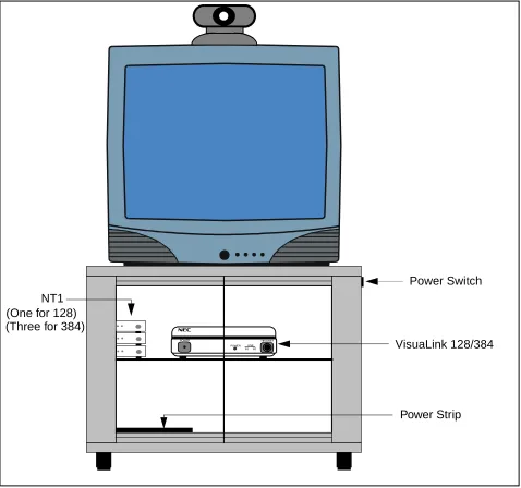
1.1 General This chapter provides general identification, installation, shipping and receiving information for the VisuaLink 128/384. The system consist of four major components, the equipment cabinet, the television monitor, the video camera and the VisuaLink 128/384 unit with remote control and cable bundle.
Depending on the system application ordered, anywhere from one to four major components (boxes) could be shipped
Figure 1-1: Rollabout 128/384 System
Note: This system contains five (5) major components: equipment cabinet, television monitor, video camera, NT1(s) and VisuaLink 128 or VisuaLink 384 unit with remote control.
POWER HEADSET
POWER LINE B1 B2
Power Strip NT1
VisuaLink 128/384 Power Switch (One for 128)
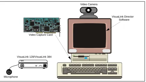
Figure 1-2: Desktop Application
Note: This system contains three major components: video camera, video capture card, and VisuaLink 128 or VisuaLink 384.
POWER HEADSET
POWER LINE B1 B2
VisuaLink 128/VisuaLink 384
Video Camera
Video Capture Card
VisuaLink Director Software
1.2 Identification Equipment Cabinet
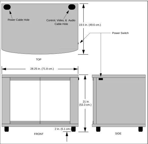
The VisuaLink 128/384 equipment cabinet consist of a metal cabinet with two Plexiglas doors that open outward. It contents a shelf on which the VisuaLink 128/ 384 control unit will be located. Also located at the rear of the cabinet is a power strip. The cabinet has two punch-out holes, one located in the lower rear for the power feed, and the other is located on the top at the rear for the monitor and camera cables.
Figure 1-3: Rollabout 128/384 Cabinet 19.5 in. (49.6 cm.)
28.25 in. (71.8 cm.)
21 in.
2 in. (5.1 cm.) TOP
FRONT SIDE
Power Switch
Power Cable Hole Control, Video, & Audio
Cable Hole
Trinitron® Color Monitor
The Sony Trinitron® Color Monitor contains the following features: • Displays On-screen menus for configuring the VisuaLink.
• Picture-in-Picture (PIP) that allows the local site to view their image seen by the distant end.
• Built-in speakers for outputting the distant sites audio.
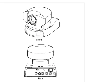
Color Video Camera
The Color Video Camera has the following features:
• Effective picture elements of 380,000 (EVI-D30) for enables high-resolu-tion shooting.
• High speed pan/tilt action controlled by the VisuaLink. • Captures the video in the local room.
Figure 1-5: Color Video Camera (Front and Rear View)
Front
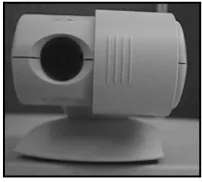
Color Video Camera for Desktop
The Color Video Camera for the desktop has the following features:
Wide-angle and a high resolution CCD imager give you wide views with high resolution.
• Compact design and flexible arm enable versatile shooting positions. • Manual focus allows sharp image from less than 0.5 inch (10mm) to infinity. • Manual iris allows good image in various lighting conditions
• Rotating camera head allows flexible angle of the picture. • Flicker reduction switch reduces flicker control.
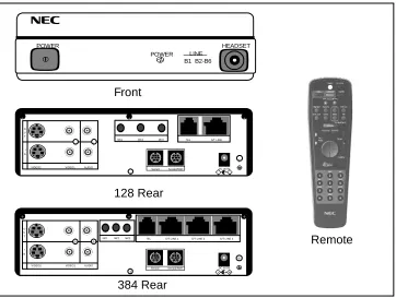
VisuaLink 128/384 Unit
The VisuaLink 128/384 simplifies video conferencing with virtually no technical expertise required. The superior motion handling allows users to concentrate on the meeting content rather than worry about the quality. With its plug-and-play technology, the unit can be operational in a matter of seconds. Just power ON the system and experience a video conference as never seen or heard before. The on-screen messages and icon driven menus were designed for even the most novice users with no training required.
Figure 1-7: VisuaLink 128/384 Unit with Remote Control
• H320 Plus Standards-Based Operation: Taking advantage of the latest revi-sions of H.320, the VisuaLink 128/384 are able to operate with a wide vari-ety of videoconferencing products and support a much broader scope of standards and features.
• H.263 Video Compression: With H.263, the VisuaLink will have better mo-tion handling in low bandwidth applicamo-tions.
• Supports S-Video Transmission and Reception: Detailed images, such as PC image, can be transported and displayed at the far-site with increased res-olution and little distortion.
• VisuaLink 128/384 is expendable to 384: The VisuaLink 128/384 is capable of being field upgraded to support 384 kbps.
• Remote Software Upgrades and Updates: By dialing into the hub center with the VisuaLink and accessing the icon menu for downloading, the latest software is automatically downloaded to the system.
POWER HEADSET POWER LINE
B1 B2-B6
Front
+
+
+ +
+
DC IN 5V + Serial1 Serial2/RMT O
U T
I N
VIDEO2 VIDEO1 AUDIO
+ +
TEL S/T LINE MIC1 MIC2 MIC3
128 Rear Remote + + + + +
DC IN 5V + Serial1 Serial2/RMT O
U T
I N
VIDEO2 VIDEO1 AUDIO
+
+ MIC1 MIC2 MIC3 TEL S/T LINE 1 S/T LINE 2 S/T LINE 3
• Integrated, All-in-One Package: The VisuaLink 128/384 includes an echo canceller, CODEC and control system, this allows simple installation and ease of use.
• Icon Menu Screen: The On-Screen Icon driven menu will allow even those of us that are not technically inclined to control the VisuaLink.
• Far-end Camera Control: Integration of H.281 allows multi-location and point-to-point far-end camera control via the International Standards. • Multipoint Control: The integration of H.243 allows for control of the MCU
from the CODEC via the International Standards. 1.3 Packaging Rollabout Package
The Rollabout 128/384 is shipped in two (2) separate boxes. The equipment cabinet is enclosed in a styroform box to protect it from damage. The box is then secured with transportation strips. The monitor is also shipped in a styroform box and secured with transportation strips. The camera and camera power supply is enclosed in styroform and then boxed. The VisuaLink 128/384 unit, remote control and cable bundle is bubble-wrapped and then boxed.
Desktop Packing
The desktop system is shipped in a minimum of two (2) boxes. The VisuaLink 128/384 unit with remote control in a box. The video capture card is shipped in a styrofoam box.
Optional Equipment
Optional equipment, such as NT1 unit, graphic camera, etc. are shipped in their own individual box.
1.4 Unpacking and Handling
Chapter 2 VisuaLink Stand-Alone System
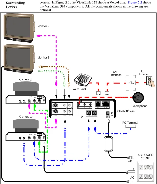
2.1 Connection of the Surrounding Devices
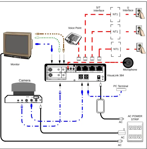
This section gives a description on how to setup a VisuaLink as a stand-alone system. In Figure 2-1, the VisuaLink 128 shows a VoicePoint. Figure 2-2 shows the VisuaLink 384 components. All the components shown in the drawing are optional.
Figure 2-1: VisuaLink 128 System Connections
+
+
+ +
+
DC IN 5V + Serial1 Serial2/RMT O
U T
I N
VIDEO2 VIDEO1 AUDIO
+
+ MIC1 MIC2 MIC3 TEL S/T LINE
AC AC VisuaLink 128 Monitor 1 VoicePoint AC POWER STRIP Microphone PC Terminal Camera 1 Video
Audio S Video IN VISCA OUT Power ON OFF MIC NT1 Monitor 2 Camera 2 Video
Audio S Video IN VISCA OUT Power ON OFF MIC
S/T U
Figure 2-2: VisuaLink 384 System Connections
Note 1: VoicePoint or microphones are optional equipment for the VisuaLink. Both cannot be operational at the same time.
Note 2: If connecting a low-end rollabout system, use the cable kit provided with the low-end cabinet.
Note 3: All cables included with the system are black in color. The above cable colors are done to clarify kits.
+
+
+ +
+
DC IN 5V + Serial1 Serial2/RMT O
U T
I N
VIDEO2 VIDEO1 AUDIO
+ +
TEL S/T LINE 1 S/T LINE 2 S/T LINE 3 MIC1 MIC2 MIC3
AC AC VisuaLink 384 Monitor Voice Point AC POWER STRIP Microphone PC Terminal Camera Video
Audio S Video IN VISCA OUT Power ON OFF MIC AC NT1 NT1 NT1
S/T U
2.2 Connection Procedure
Procedure for connecting a stand-alone VisuaLink. See Appendix A for system layout of the VisuaLink 128. See Appendix B for the system layout for the VisuaLink 384.
1. Connecting the Video Out of the VisuaLink to the TV Monitor
Using the attached video cable, that comes with the VL, plug one side into the TV Monitor connection marked VIDEO 1 INPUT. Plug the other end into the connection marked VIDEO OUT 1 on the VisuaLink.
2. Connecting audio from the VisuaLink to the TV Monitor. (optional)
Using the provided audio cable, that comes with the VL, plug one end into the AUDIO INPUT 1 of the TV Monitor. Plug the other end into the AUDIO OUTPUT of the VisuaLink.
Note: If a VoicePoint is used do not connect the audio output connection.
3. Connecting the Voicepoint to the VisuaLink. (optional)
Using the attached RJ11 cable of the VoicePoint, plug the open end into the VisuaLink connection labeled TEL.
4. Connecting the NT1 device to the VisuaLink. (optional)
Using the provided data cable (RJ45 - RJ45), plug one end into the VisuaLink connection labeled ST/LINE. The other end of the cable, plugs into the NT1 device. Repeat procedures if connecting a VisuaLink 384 and three NT1s. Note: If the NT1 device is located more than 300 ft. (91 m.) away. Set the
VL128 TERM SWITCH located on the back of the unit to the ON position. Set the VL384 STRIP SETTING inside the unit to the ON position.
5. Connecting a microphone to the VisuaLink. (optional)
Plug the 3 1/2 mini connector into the VisuaLink connection marked MIC1. 6. Connecting the Video Camera to the VisuaLink. (optional)
Using the provided video cable, plug one end into the connection marked VIDEO OUT on the D30 camera. Plug the other end of the video cable into the VisuaLink connection labeled VIDEO IN 1.
7. Connecting the camera control to the VisuaLink. (optional)
With a 8 pin minidin to 8 pin minidin, plug one end into the D30 camera connection marked VISC IN. Plug the other end into the VisuaLink connection marked SERIAL 1.
8. Connecting the camera power. (optional)
9. Connecting a PC to the VisuaLink for data sharing. (optional)
Using an 8-pin mini din to DB9 cable, plug the 8-pin end into the VisuaLink connection marked SERIAL 2/RMT. Plug the other end into the PC. 10. Connecting the VisuaLink AC Power.
Using the provided AC transformer power cable, plug the power cable into the VisuaLink connection marked DC-IN-5V. Plug the other end into the AC Power Strip.
Chapter 3 Startup Screen for the VisuaLink 128 and VisuaLink 384
When you first turn on your VisuaLink, there will be an initial configuration screen. These configuration screens will have to be completed before your system becomes operational.
3.1 Start up configuration screens
The following are the startup screens that will be active on first power up or acti-vated on demand by the user after choosing the Environmental initialize.
Welcome Screen:
This is a welcome screen for the User.
VisuaLink
Thank you for purchasing one of the most simple and portable video conferencing systems available.
We will now show you how to set up your system. This will only have to be done once.
NOTE: If remote controller doesn’t work, make sure the switch setting of D30 camera IR out is ON. Switch is located on the bottom of the camera.
Click here to continue Configure later
▲
Remote Controller Directions:
Gives some general directions for configure the VisuaLink system. Using the Remote controller highlight the NEXT option to advance to the configure screen or press the lower portion of the CAMERA CONTROL key to highlight the Configure Later to advance to the normal ICON screens. If you choose to configure later, the system will have to be programmed with My numbers and SPID’s in order to work correctly.
3.2 Setting Up your ISDN Line Information
The following is a description of BRI Line setup
Part 1- Remote Controller Location
- Locate the CAMERA control.
The CAMERA control key is the BLUE round key. Use this key to move the Cursor
up/down and Left/Right in the Configuration Screens.
- Locate the ENTER key on the Wireless remote controller.
Use the ENTER key to confirm selections and store information.
Next screen Prior screen
▲
Part 2- Setting up Your ISDN Line Introduction:
When ordering BRI service, you will usually get 2 My numbers and 2 SPID numbers per BRI. A SPID normally consists of the user’s 3 digit area code, 7 digit ISDN telephone number, followed by a 0101. Ex:
MY Number 1: 9727195854
SPID 1: 97271958540101
Note: The VisuaLink 128 requires 2 My numbers and 2 SPID #, while the VisuaLink 384 requires 6 My numbers and 6 SPID #.
Next screen Prior screen
▲
Video Number 1 Screen’s
Using the number pad of the wireless remote enter My Number with area code and SPID numbers associated to Line (BRI 1). Each BRI will have My numbers labeled #1 and #2 and two SPID’s. All four numbers must be entered. Choose NEXT when complete.
Note: “PROCEED TO STEP 2” will only be shown on the VisuaLink 128 system. VisuaLink 384 will show “Proceed to Line 2 Setup”
Step 1--Enter My Number and SPID for BRI LINE 1
My Number 1:
[ ]
SPID 1:
[ ]
My Number 2:
[ ]
SPID 2:
[ ]
Next screen Prior screen
Press ENTER after choosing each item
▲
Step 1--Enter My Number and SPID for BRI LINE 1
My Number 1: [9727195854] SPID 1:
[97271958540101] My Number 2:
[9727195855] SPID 2:
[97271958550101 ]
Next screen Prior screen
Press ENTER after choosing each item
Video Number 2 Screens:
Using the number pad of the wireless remote enter My Number with area code and SPID numbers associated to Line (BRI 2). Each BRI will have My numbers labeled #1 and #2 and two SPID’s. All four numbers must be entered. Choose NEXT when complete.
Note: This screen will only appear on the VL 384 system.
Step 1--Enter My Number and SPID for BRI LINE 2
My Number 1:
[ ]
SPID 1:
[ ]
My Number 2:
[ ]
SPID 2:
[ ]
Next screen Prior screen
Press ENTER after choosing each item
Video Number 3 Screens:
Using the number pad of the wireless remote enter My Number with area code and SPID numbers associated to Line (BRI 3). Each BRI will have My numbers labeled #1 and #2 and two SPID’s. All four numbers must be entered. Choose NEXT when complete.
Note: This screen will only appear on the VL 384 system.
3.3 Optional User Settings:
The following is a description for Optional Setting screen.
Step 1--Enter My Number and SPID for BRI LINE 3
My Number 1:
[ ]
SPID 1:
[ ]
My Number 2:
[ ]
SPID 2:
[ ]
Next screen Prior screen
Press ENTER after choosing each item
▲
Part 3 - Optional User Settings
Introduction:
Site Name: Name identification for your
location. Name is displayed on far-end monitor when site is viewed.
Password: Required to gain access to the VisuaLink configuration screens.
Time display: Sets the internal clock for the VisuaLink.
Next screen Prior screen
Optional information:
You may enter this optional information. The name you enter makes it easy for users to identify this particular VisuaLink. The name can be up to 20 characters long. The Password is the password needed to be entered when selecting the Utilities ICON. After entering the optional information select the NEXT to advance to the next screen.
Application Screen’s
Using the number pad on the wireless remote controller select the application which the VisuaLink is installed. Your answer to this question will automatically configure the internal parameters for the following:
Step 1- Optional User Settings
Your Site Name [ ]
Password [ ] Time Setting [12/1/1998 10:50]
Time Display: <Time only>
Auto Power Save: <OFF>
Next screen Prior screen
Press ENTER after choosing each item
▲
Item Rollabout/Other Data Conference Gateway Desktop
Serial Port 1 Camera EVI-D30 T.120 Camera Camera
Serial Port 2 Console Console Console Console
Audio Mode G.722 G.728 G.722 G.722
MLP 4.0 24.0 4.0 4.0
Answer Mode Auto Auto Auto Manual
LSD 1.2 Off 1.2 1.2
Ext. Remote Auto Off Off Off
H.263 Off Off Off Off
Congratulations Screen
The VisuaLink is now setup for the configuration you have entered. Press the ENTER button on the REMOTE CONTROLLER, the VisuaLink will display a blue screen and recycle. The VisuaLink should will power up to a normal state. You may begin to use the video conferencing system immediately.
Note: If there are no My Numbers entered in the configuration the VisuaLink will display the Start Up screens.
Step 2—Optional User Settings
Key in the number of one of the following applications.
Applications:
1. Rollabout/Other 2. Data Conference 3. Gateway 4. Desktop
Press CANCEL to page back
Congratulations, you have just finished setting up your VisuaLink system.
For VisuaLink software updates and general VisuaLink knowledge, visit the NEC Knowledge base web site at :
http://www.cng.nec.com or
http://www.ilibrary.com/phoenix/ntachome.nsf /homepagenav?opennavigator
- You may begin to use the video conferencing system immediately.
- Press ENTER to activate your configuration.
VisuaLink system start up screen.
Changing the configuration
It is important that the CODEC is set up with a local number and SPID numbers. If the unit is not setup with a local number (my number) and SPID, the unit will not allow for dialing and receiving of video calls. If you have entered these numbers in the Start Up configuration, you may ignore this section. If the VisuaLink environment has changed, such as the phone number have changed, you must reconfigure the numbers in the VisuaLink.
America, Inc.
VisuaLink
Powering Up
Chapter 4 Rollabout 128/384 Procedures
4.1 Rollabout System Connections
Use the following procedures to set up the VisuaLink 128 or VisuaLink 384. See
Appendix A for system drawings for the VisuaLink 128. See Appendix B for the
system drawings for the VisuaLink 384.
Note: This guide provides connection diagrams for manufacturer-specific
components. If your system contains components from other manufacturers, please consult their documentation.
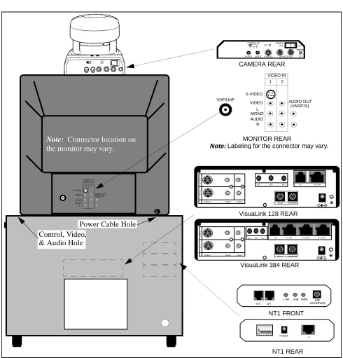
Figure 4-1: Equipment Placement
1 2 VIDEO IN S-VIDEO VIDEO AUDIO L MONO R AUDIO OUT (VAR/FIX) 1 2 VIDEO IN S-VIDEO VIDEO AUDIO L MONO R AUDIO OUT (VAR/FIX) + + + + +
DC IN 5V + Serial1 Serial2/RMT O
U T
I N
VIDEO2 VIDEO1 AUDIO
+
+ MIC1 MIC2 MIC3 TEL S/T LINE
AUDIO VIDEOS VIDEO IN VISCA OUT POWER OFF ON DC IN 13.5 V + -MIC CAMERA NO.
1 2 3
CAMERA REAR
MONITOR REAR
VisuaLink 128 REAR
NT1 REAR
VHF/UHF
S/T S/T
L-BK LINE PWR DIN
INTERFACE
1 2 3 4 5
ON POWER U NT1 FRONT + + + + +
DC IN 5V + Serial1 Serial2/RMT O
U T
I N
VIDEO2 VIDEO1 AUDIO
+ +
TEL S/T LINE 1 S/T LINE 2 S/T LINE 3 MIC1 MIC2 MIC3
VisuaLink 384 REAR
Note: Connector location on
the monitor may vary. Note: Labeling for the connector may vary.
Control, Video, & Audio Hole
4.2 Step-by-Step Procedure
The following are the steps and procedures for the installation of the VisuaLink 128/384.
STEP ACTION DRAWING
1. Locate and unpack the Cabinet box.
2. Locate Power Strip at bottom-left (looking through the front) of cabinet and feed power cable through the power opening at rear of cabinet.
3. Plug power strip power cable into AC outlet. Make sure the ON/OFF switch on the upper right outside of the cabinet is in the OFF position. Note: The power switch will be lit when the
power strip is in the ON position.
Powerstrip
4. Remove Monitor from monitor box.
4a. Place TV monitor on top of cabinet.
5. Locate monitor power cable and feed through the cable opening at the top of cabinet.
6. From inside the cabinet, plug the monitor power cable into power strip.
STEP ACTION DRAWING
12 VIDEO IN S-VIDEO
VIDEO AUDIO L MONO
R AUDIO OUT(VAR/FIX)
Power Cable
7. Locate the cable bundle and remove from packing box. The cable bundle contains two (2) 5 in. (12 cm.) Velcro strips. Use these strips to mount the camera to the top of the monitor.
8. Locate the camera box and remove camera.
9. Set the IR switch on the Sony D30 camera to the ON position. The IR switch is located on the bottom of the Sony D30 camera. This will allow for the Sony Camera to receive the IR codes from the VisuaLink remote controller and transmit them to the VisuaLink Codec for control.
Mount the camera on the top of monitor, using the Velcro strips. Make sure the front of the camera is flush with the front of the monitor and the camera is centered.
STEP ACTION DRAWING
Foam Inserts
Polyethylene Bag
Packing Carton
Velcro Strips
10. Locate the camera power cable. Plug the camera power cable into the power strip in cabinet, then feed cable through top of cabinet and plug into the rear of the camera.
11. Locate the VisuaLink 128/384 and remove from packing box.
12. Place the VisuaLink 128/384 on the second shelf of the cabinet.
STEP ACTION DRAWING
12 VIDEO IN S-VIDEO
VIDEO AUDIO L MONO
R AUDIO OUT(VAR/FIX)
Video Power Cable
Power Cable Hole
Polyethylene Bag
Foam Inserts
Packing Carton
13. Locate the VisuaLink 128/384 power cable. Plug cable into power strip at bottom of cabinet and feed cable through cable slot in rear of second shelf. Plug second end of power cable into power input at rear of the VisuaLink 128/384.
14. The cable bundle is labeled at the ends of the various connectors. Plug these connectors into the appropriate devices (camera/monitor) and feed down through opening at top of cabinet. See
Figure 2-1.
Note: Connector layout could vary by manufacturer. Please consult your equipment documentation if connector layout is different.
STEP ACTION DRAWING
Power Plug Connection
+
+
+ +
+
DC IN 5V
+ Serial1 Serial2/RMT
O U T
I N
VIDEO2 VIDEO1 AUDIO
+
+ MIC1 MIC2 MIC3 TEL S/T LINE
VisuaLink 128 Rear
+
+
+ +
+
DC IN 5V + Serial1 Serial2/RMT O
U T
I N
VIDEO2 VIDEO1 AUDIO
+ +
TEL S/T LINE 1 S/T LINE 2 S/T LINE 3 MIC1 MIC2 MIC3
VisuaLink 384 Rear
Power Plug Connection
VISCA In 1 2 VIDEO IN S-VIDEO VIDEO AUDIO L MONO R AUDIO OUT (VAR/FIX) Camera Control Sony D30 Camera Vout CAMERA MONITOR VHF/UHF Monitor Vin
Monitor Audio L (Cable)
15. Inside the cabinet, connect the other ends of the cable bundle to the VisuaLink 128/384. See
Figure 2-1.
16. Locate and unpack the microphone and connect the 3.5 inch plug into the VisuaLink connection marked "MIC1". String the MIC cable out of the rear of the cabinet. Connect the other end of the cable into the Microphone and place on table.
STEP ACTION DRAWING
+
+
+ +
+
DC IN 5V
+ Serial1 Serial2/RMT
O U T
I N
VIDEO2 VIDEO1 AUDIO
+
+ MIC1 MIC2 MIC3 TEL S/T LINE
Serial 1 VisuaLink 128/384
(Cable) Video In
(Cable)
VisuaLink 128 Rear Video Out
(Cable) Audio Output(Cable)
+
+
+ +
+
DC IN 5V + Serial1 Serial2/RMT O
U T
I N
VIDEO2 VIDEO1 AUDIO
+ +
TEL S/T LINE 1 S/T LINE 2 S/T LINE 3 MIC1 MIC2 MIC3
VisuaLink 384 Rear Video Out
(Cable) Audio Output
(Cable) Serial 1 (Cable) VisuaLink 128/384 Video In (Cable) + + + + +
DC IN 5V
+ Serial1 Serial2/RMT
O U T
I N
VIDEO2 VIDEO1 AUDIO
+
+ MIC1 MIC2 MIC3 TEL S/T LINE
MIC1
+
+
+ +
+
DC IN 5V + Serial1 Serial2/RMT O
U T
I N
VIDEO2 VIDEO1 AUDIO
+ +
TEL S/T LINE 1 S/T LINE 2 S/T LINE 3 MIC1 MIC2 MIC3
VisuaLink 384 Rear VisuaLink 128 Rear
17. If an NT1 device has been purchased, locate the device and unpack.
Note 1: If a NT1 was not purchased go to Step 23. Note 2: Three NT1 are used for the VL384.
18. Locate the dip switch on the rear of the NT1 and set all to the ON position.
19. Place the NT1 or the three NT1s on the second shelf, to the right of the VisuaLink 128/384.
20. Locate the NT1 power cable. Plug cable into power strip at bottom of cabinet and feed cable through cable slot in rear of second shelf. Plug second end of power cable into power input at rear of the NT1.
STEP ACTION DRAWING
Polyethylene Bag
Foam Inserts
Packing Carton
1 2 3 4 5
ON
1 2 3 4 5
ON
POWER U
NT1 REAR
POWER HEADSET POWERLINEB1 B2
NT1
VisuaLink 128/384 (one for 128)
(three for 384)
1 2 3 4 5
ON
POWER U
21. Locate the network cable (RJ45-RJ45) and connect one end to the S/T line port of the VisuaLink 128/384. Connect the other end of the network cable into the S/T interface of the NT1. Note: Use the RJ45-RJ45 cable that is included
with the NT1 unit.
22. Connect the network cable from the U interface on the NT1 to the network jack provided on the room wall. Proceed to Step 24.
Note 1: Use the RJ45-RJ45 cable that is included with the NT1 unit.
Note 2: If connecting a VisuaLink 384, Step 21 will have to be repeated three (3) time.
STEP ACTION DRAWING
+
+
+ +
+
DC IN 5V
+ Serial1 Serial2/RMT
O U T
I N
VIDEO2 VIDEO1 AUDIO
+
+ MIC1 MIC2 MIC3 TEL S/T LINE
RJ45 NT1 Cable
S/T S/T
L-BK LINE PWR DIN
INTERFACE
ST Interfaces
VisuaLink 128 Rear
NT1 Front
+
+
+ +
+
DC IN 5V + Serial1 Serial2/RMT O
U T
I N
VIDEO2 VIDEO1 AUDIO
+ +
TEL S/T LINE 1 S/T LINE 2 S/T LINE 3 MIC1 MIC2 MIC3
VisuaLink 384 Rear RJ45 NT1 Cable
1 2 3 4 5
ON
POWER
U NT1 Rear
23. Locate the network cable (RJ45-RJ45) and connect one end to the S/T line port of the VisuaLink 128/384. Connect the other end of the network cable into the network interface provided in the room wall.
Note 1: If the NT1 or network switch resides 300 ft. (91 m.) or more away from the VisuaLink 128/384, it is recommended that the TERM switch is set to ON on the VL128.
Note 2: In the case a VL384 is being installed, remove the network interface card from the system and set the required straps. Note 3: f the VL 384 is being installed, Step 23
must be repeated three (3) times.
24. Locate the ON/OFF switch at the upper right outside of the cabinet. Press the switch to the ON position.
STEP ACTION DRAWING
+
+
+ +
+
DC IN 5V
+ Serial1 Serial2/RMT
O U T
I N
VIDEO2 VIDEO1 AUDIO
+
+ MIC1 MIC2 MIC3 TEL S/T LINE
RJ45 NT1 Cable
+
+
+ +
+
DC IN 5V + Serial1 Serial2/RMT O
U T
I N
VIDEO2 VIDEO1 AUDIO
+ +
TEL S/T LINE 1 S/T LINE 2 S/T LINE 3 MIC1 MIC2 MIC3
VisuaLink 384 Rear RJ45 NT1 Cable VisuaLink 128 Rear
25. Verify that all the equipment plugged into the power strip are turned to the ON position. The VisuaLink 128/384, camera and monitor have their own power switches. If a device appears to be still in the OFF position, check the power connection from the Power Strip to the device. The NT1 does not have a power switch. The green LED on the front of the NT1 is an indication the unit is powered ON.
Note: Make sure the monitor is selected for Video 1.
26. When the VisuaLink 128/384 is powered ON, a display of the NEC America, Inc. logo, VisuaLink name, POWERING UP and version number will be displayed on the monitor.
STEP ACTION DRAWING
POWER HEADSET POWERLINEB1 B2
Powering Up 22.99.99
VisuaLink
Chapter 5 Upgrading a VL 128 to a 384
This chapter contains instructions for upgrading your VisuaLink 128 system to a VisuaLink 384. If you have any questions about the upgrade, please call your video conference provider.
5.1 Upgrade Instructions
To upgrade your system, purchase the 384 upgrade kit (Stock # 0291421) from video conference provider and follow the easy step-by-step instructions
mentioned below. When upgrading a system you must start with the Hardware Procedure and finish up with Environmental Initialize.
5.2 Apparatus 384 Upgrade kit (Stock # 0291421) Phillips Screw Driver (needed) Grounding Strap (needed)
Note: The speed setting should be set to 2B (128 kbps). This will make sure the upgrade is completed in a matter minutes instead of hours. When the upgrade is complete, power OFF your system and continue on to the hardware Upgrade Procedure.
5.3 Hardware Upgrade Procedure
1. If cables are connected to the rear of the system and are not labeled, label all the cables. This will help to identify which cable is connected to which port when the upgrade is complete.
2. Unplug all the all cables including the power cable, which is plugged into the rear of the VL 128.
3. Strap on the Grounding Strap.
CAUTION
All video cards are sensitive to electrostatic discharge. Slight discharges from clothing or even from the normal work environment can adversely affect these cards. By following these simple guidelines, however, you can minimize the chance of damaging your video cards.
• Handle cards only by the non-conducting edges.
• Do not touch the card components or any other metal parts.
• Wear a grounding strap while handling the cards (if in a high static area). • Ensure that the workstation is powered OFF before installing any
4. Using a Phillips screwdriver, remove the four (4) screws that attach the cover panel to the housing of the VL 128. The four screws are located on the bottom of the VL 128.
Note: While in this position, place the Upgrade Label supplied with the Upgrade Kit at the position shown in the illustration below. The label shows the VisuaLink 128 has been upgraded to a VisuaLink 384. Do not block the air grid when placing label.
5. Using a Phillips screwdriver, remove the three (3) screws that attach the cover panel to the housing of the VL 128. The four screws are located on the rear of the VL 128.
6. Slid the cover towards the rear of the chassis, to remove. Using a Phillips screwdriver remove the four (4) screws from the rear panel.
Screws Screws
Upgrade Lable
Upgrade Label
Screws
7. Remove the rear panel from the VisuaLink housing.
8. Locate the AEC7M card. With a Phillips screwdriver remove three (3) screws which attach the AEC7M card to the BRI interface.
Note: Two (2) of the three (3) screws are on the AEC7M. One (1) screw is on the BRI board.
9. As the AEC7M and the BRI interface are connected at the front center of each panel, pull the connectors apart, being careful not to break either unit.
10.Locate the 384 IMUX card. Unpack the 384 IMUX card from the packaging and place the card on a non-static bag.
BRI Board
AEC7M
Screws Screw
Board
11. Confirm that there are two supports on the 384 IMUX card at the locations.
12.Put the AEC7M and the 384 IMUX card connectors together and tightly connect both as shown. Fasten the AEC7M card to the 384 IMUX card with the three (3) screws.
13.Place the 384IMUX card on the non-static bag or surface.
Supports
14.Using the Phillips screwdriver, remove the three (3) screws that attach the BRI interface to the mother board. Remove the BRI interface card from the motherboard and replace with the 384 IMUX card. Place the BRI interface card on the non-static bag or surface.
Note: The BRI interface and the motherboard are connected on the right side of each card, pull the connectors apart, being careful not to break either unit.
15.Fasten the 384 IMUX card to the motherboard.
16.Locate the 384 rear panel.
Screws
Screw
Connector
Mother Board 384 IMUX Card
DC IN 5V + Serial1 Serial2/RMT O
U T
I N
VIDEO2 VIDEO1 AUDIO
17.Using a Phillips screwdriver fasten the 384 rear panel to the housing of the VL. 18.Locate the VL cover panel and fasten back onto the VL.
19.Connect all cables which where previously connected to the VL. 20.The Hardware Installation is complete, continue on to the last step
Environmental Initialize. 5.4 Environmental
Initialize
1. Press the MENU button on the wireless remote controller (See diagram below). 2. Using the wireless remote controller select the On-Screen icon labeled
SETTING ENVIRONMENTS.
3. Press the ENTER button.
4. Enter the PASSWORD and press the ENTER button on the wireless controller. 5. Using the wireless remote controller MOVE button select the ON-Screen icon
labeled MAINTENANCE. 6. Press the ENTER button
7. Locate the PAGE UP button on the wireless remote controller. Press the ONE button.
8. Using the wireless remote controller CAMERA CONTROL button select the environmental initialize.
9. When the environmental initialize is complete, the system asks you to restart the system.
10.Restart the system.
PAGE UP
ENTER
ONE
MENU
Chapter 6 VL128/384 Desktop Videoconference
6.1 General Description
The VL128/384 is a device used in a multimedia conference for transmitting video, audio and data to a remote location with the use of BRI Networks. The object is to show how the VL128/384 is used in a desktop videoconference application.
6.2 System Requirements
This section describes the minimum and recommended system requirements for the VL128/384 Workstation Application.
Workstation (Which are not video enabled)
The following are the minimum specifications for a workstation PC which will be used for a desktop videoconference application
• Pentium/Pentium Pro, or compatible system with PCI Locus Bus • Expansion Slot- 32 bit PCI Local Bus
• Operating System- Windows 95
• Video Monitor capable of VGA (640 X 480) resolution or greater • Slot available for Video capture card with the ability to display NTSC
composite or S-Video
• Sound Card with a RCA or mini phono adapter input Workstations (Which are video enabled)
Require the following:
• Video Capture Card with the ability to display NTSC composite or S-Video input.
• Sound Card Audio with a RCA or Mini Phono adapter input. • Sound Card is not needed if amplified Speakers are provided. Additional Hardware/Software Requirements
In addition to the workstations the following components are necessary for a desktop videoconference.
Items VisuaLink 128 VisuaLink 384
VL128 1 N/A
VL384 N/A 1
NT-1* 1 1(up to 3)
Microphones 1(up to 3) 1(up to 3) Video Camera 1(up to 2) 1(up to 2)
Video Capture Card** 1 1
Director Software*** 1 1
* When BRI network terminates directly into the VisuaLink (Bypass the PBX) an NT-1 is required.
** If the workstation is currently not equipped with a Video Capture Card, one is needed.
6.3 Wiring Diagram This chapter provides general identification, installation, shipping and receiving for the VisuaLink 128/384 Desktop Videoconference Application. The system consists of three major components, the equipment such as the Video Capture card, the VisuaLink 128/384 with remote control, microphone and Camera.
Figure 6-1: VisuaLink 128/384 Desktop Videoconference Application - Front View
POWER HEADSET
POWER LINE B1 B2
VisuaLink 128/VisuaLink 384
Video Camera
Video Capture Card
VisuaLink Director Software
Figure 6-2: VisuaLink128/384 Desktop Videoconference Application - Rear View
6.4 Packaging System Package
The Desktop VL 128/384 application is shipped in a minimum of four (4) separate boxes. The Video capture card is enclosed in electrostatic box to protect it from damage. The fixed or Controllable Camera (which ever was ordered), NT1, and Microphone are enclosed in their own Styrofoam box. The VisuaLink 128 unit and remote controller are wrapped in their own electrostatic box.
6.5 Unpacking and Handling
Follow the procedures shown in Desktop installation procedures. Do not unpack items until they are required for use.
VisuaLink 128
Video Capture Card Video Camera
+
+
+ +
+
DC IN 5V
+ -Serial -Serial2/RMT O U T I N
VIDEO2 VIDEO1 AUDIO
+
+ MIC1 MIC2 MIC3 TEL S/T LINE
VisuaLink 384
+
+
+ +
+
DC IN 5V
+
-Serial1 Serial2/RMT O
U T I N
VIDEO2 VIDEO1 AUDIO
+ +
.
+
+
+ +
+
DC IN 5V + Serial1 Serial2/RMT O
U T
I N
VIDEO2 VIDEO1 AUDIO
+
+ MIC1 MIC2 MIC3 TEL S/T LINE
AC AC VisuaLink 128 AC POWER STRIP Microphone PC Terminal PC Camera AC
Video Capture Card
RS-232C (COM1) U Interface S/T Interface AC V i d e o O u t A u d i o O u t Video In Audio In Amplified Speakers (Optional)
NT1
COM Port 2
VIDEO DC IN 6V
COM Port 1
VGA Port
Note 1: PC backpanel may be different than the one shown. Reference the PC manual and Capture card for location of connectors.
Figure 6-4: Wiring Diagram for VisuaLink 384 NT1 + + + + +
DC IN 5V + Serial1 Serial2/RMT O
U T
I N
VIDEO2 VIDEO1 AUDIO
+ +
TEL S/T LINE 1 S/T LINE 2 S/T LINE 3 MIC1 MIC2 MIC3
AC AC VisuaLink 128 AC POWER STRIP Microphone PC Terminal PC Camera AC
Video Capture Card
RS-232C (COM1) U Interface S/T Interface AC V i d e o O u t A u d i o O u t Video In Audio In
Amplified Speakers (Optional)
NT1 NT1
COM Port 2
VIDEO DC IN 6V
COM Port 1
VGA Port
Note 1: PC backpanel may be different than the one shown. Reference the PC manual and Capture card for location of connectors.
6.6 Hardware Installation
This procedure provides instruction on how to connect a VL128/384 to a Computer.
1. Locate unpack and install Video Capture Card
Please follow Manufactures Installation procedure for Video Capture Card.
2. Locate and unpack VL128/384, Power Supply Transformer, Power Cord Audio/Video Cable (RCA to RCA) and Wireless Remote Control
3. Place the VL128/384 next to the PC. The VL128/384 must not be installed on its side. It must lay flat.
4. Take the VL128/384 Power Cord and insert two-prong plug into WALL OUTLET and the other end into the VL POWER SUPPLY
TRANSFORMER.
5. Take the Power Supply Transformer and plug into DC IN 5V port on the back of VL128/384.
6. On the backside of the VL128/384 locate the connector labeled VIDEO OUT1 and AUDIO OUT. See Figure 6-3 and Figure 6-4.
7. Using the Audio/Video cable which was included with the VL128/384 system, plug the yellow (RCA) connector into the VIDEO OUT1 and plug the white (RCA) connector into the AUDIO OUT. See Figure 6-3 and Figure 6-4. 8. On the PC side, locate other end of the audio/video cable and connect the
yellow jack into VIDEO IN of the Video capture card. Then connect the white jack into the LINE IN of your Sound Card, this connection may require the addition of a RCA to 3.5 mm mini phono adapter (included).
9. If using external speakers, be sure to connect to the SPEAKER OUT of your sound card or line out of your sound card if using amplified speakers). If the workstation does not have a sound card, connect the speakers directly into the VL128/384.
10. Locate and unpack the Audio Technica AT841/INT Microphone. Insert the 3.5 mm mini phono plug into the VL MICROPHONE INPUT 1 (MIC1) which is located on the back of the VL128/384.
11. Locate and unpack the PC Camera IK-M28, power Transformer and the single RCA to RCA video cable.
12. Place the PC Camera next to or on top of the PC, plug the power transformer into the WALL OUTLET and the other end into DC IN 6V port on the back of the camera.
13. On the Camera side, insert one end of the video cable into the VIDEO OUT port of the camera.
14. On the VL128/384 side insert the other end of the video cable into the VIDEO-IN port of the VL128/384.
15. Press the POWER SWITCH on the front of the VL128/384 to turn on. 16. If BRI Network terminates through the PBX, proceed to Step 24. If the BRI
18. Plug Power Transformer into wall outlet, Plug other end of Power Transformer into the POWER PORT of the NT-1 Device.
19. Take your Network Cable and plug one end into your provided BRI
NETWORK JACK (Wall) and plug the other end into the port marked U on the NT-1 Device.
20. Take Network Cable (included with your VL128/384) and plug one end into the S/T LINE port (either one) located on the NT-1 device.
21. Take the other end of VL provided Network Cable and insert it into S/T LINE port located at the back of the VL128/384.
22. If installing a VL384 (Bypassing the PBX) then 3 NT-1 devices will be needed. Steps 17 through 21 will need to be repeated.
23. Locate the Network Cable (RJ45-RJ45) and connect one end to the S/T LINE port of the VL128/384. Connect the other end of the Network cable into the NETWORK INTERFACE provided in the room. Proceed to Step 25.
Note: This step must be repeated 3 times if installing a VL384.
24. Connect the ST/LINE interface of the VL 128/384 into the WALL JACK. 25. Setup is complete.
Currently there are two ways to control and operate the VL 128/384. The first type of control is using the wireless remote control unit. No matter which control method is finally chosen, it is recommended that the wireless controller be used to setup the VL. Proceed to the start up configuration procedure and return to this section when completed.
Appendix A System Setup for the VisuaLink 128
Figure A: Set up for VisuaLink 128 (1 of 2) 1 2 VIDEO IN S-VIDEO VIDEO AUDIO L MONO R AUDIO OUT (VAR/FIX) 1 2 VIDEO IN S-VIDEO VIDEO AUDIO L MONO R AUDIO OUT (VAR/FIX) + + + + +
DC IN 5V + Serial1 Serial2/RMT O
U T
I N
VIDEO2 VIDEO1 AUDIO
+
+ MIC1 MIC2 MIC3 TEL S/T LINE
AUDIO VIDEO S VIDEO IN VISCA OUT POWER OFF ON DC IN 13.5 V + -MIC CAMERA NO.
1 2 3
CAMERA REAR
MONITOR REAR
VisuaLink 128 REAR
NT1 REAR
VHF/UHF
S/T S/T
L-BK LINE PWR DIN
INTERFACE
1 2 3 4 5
ON
POWER U
NT1 FRONT
Note: Connector location on
the monitor may vary. Note: Labeling for the connector may vary.
Power Cable Hole Control, Video,
Figure A: Set up for VisuaLink 128 (2 of 2)
+
+
+ +
+
DC IN 5V + Serial1 Serial2/RMT O
U T
I N
VIDEO2 VIDEO1 AUDIO
+
+ MIC1 MIC2 MIC3 TEL S/T LINE
AC AC VisuaLink 128 Monitor 1
VoicePoint
AC POWER STRIP Microphone
PC Terminal Camera 1
Video
Audio S Video IN VISCA OUT Power ON OFF MIC
AC NT1 Monitor 2
Camera 2
Video
Audio S Video IN VISCA OUT Power ON OFF MIC
Appendix B System Setup for the VisuaLink 384
Figure B: Set up for VisuaLink 384 (1 of 2) 1 2 VIDEO IN S-VIDEO VIDEO AUDIO L MONO R AUDIO OUT (VAR/FIX) 1 2 VIDEO IN S-VIDEO VIDEO AUDIO L MONO R AUDIO OUT (VAR/FIX)
AUDIO VIDEO S VIDEO IN VISCA OUT POWER OFF ON DC IN 13.5 V + -MIC CAMERA NO.
1 2 3
CAMERA REAR
MONITOR REAR
NT1 REAR
VHF/UHF
S/T S/T
L-BK LINE PWR DIN
INTERFACE
1 2 3 4 5
ON POWER U NT1 FRONT + + + + +
DC IN 5V + Serial1 Serial2/RMT O
U T
I N
VIDEO2 VIDEO1 AUDIO
+ +
TEL S/T LINE 1 S/T LINE 2 S/T LINE 3 MIC1 MIC2 MIC3
VisuaLink 384 REAR
Note: Connector location on
the monitor may vary. Note: Labeling for the connector may vary.
Power Cable Hole Control, Video,
Figure B: Set up for VisuaLink 384 (2 of 2)
+
+
+ +
+
DC IN 5V + Serial1 Serial2/RMT O
U T
I N
VIDEO2 VIDEO1 AUDIO
+ +
TEL S/T LINE 1 S/T LINE 2 S/T LINE 3 MIC1 MIC2 MIC3
AC AC VisuaLink 384 Monitor
VoicePoint
AC Power Strip Microphone
PC Terminal Camera
Video
Audio S Video IN VISCA OUT Power ON OFF MIC
AC NT1 NT1
NT1