Correct Program Execution
?Jonathan Bootle, Andrea Cerulli, Jens Groth, Sune Jakobsen, Mary Maller??
University College London
Abstract. There have been tremendous advances in reducing interaction, communication and verification time in zero-knowledge proofs but it remains an important challenge to make the prover efficient. We construct the first zero-knowledge proof of knowledge for the correct execution of a program on public and private inputs where the prover computation is nearly linear time. This saves a polylogarithmic factor in asymptotic performance compared to current state of the art proof systems. We use the TinyRAM model to capture general purpose processor com-putation. An instance consists of a TinyRAM program and public inputs. The witness consists of additional private inputs to the program. The prover can use our proof system to convince the verifier that the program terminates with the intended answer within given time and memory bounds. Our proof system has perfect completeness, statistical special honest verifier zero-knowledge, and computational knowledge soundness assuming linear-time computable collision-resistant hash functions exist. The main advantage of our new proof system is asymptotically efficient prover computation. The prover’s running time is only a superconstant factor larger than the program’s running time in an apples-to-apples comparison where the prover uses the same TinyRAM model. Our proof system is also efficient on the other performance parameters; the verifier’s running time time and the communication are sublinear in the execution time of the program and we only use a log-logarithmic number of rounds.
Keywords. Zero-knowledge proofs, succinct arguments of knowledge, TinyRAM, ideal linear commitments.
1
Introduction
A zero-knowledge proof system [GMR85] enables a prover to convince a verifier that a statement is true without revealing anything else. We are interested in proving statements of the form u ∈ L, where L is a language in NP. A zero-knowledge proof is an interactive protocol between a prover and a verifier, where both hold the same instance u, and the prover also holds a witnesswtou∈ L. The protocol should satisfy three properties:
?
The research leading to these results has received funding from the European Research Council under the European Unions Seventh Framework Programme (FP/2007-2013) / ERC Grant Agreement n. 307937
??
Completeness: A prover holding a witness tou∈ Lcan convince the verifier.
Soundness: A cheating prover cannot convince the verifier whenu /∈ L.
Zero-knowledge: The interaction only shows the statementu∈ Lis true. It
reveals nothing else, in particular it does not disclose anything of the witness. Zero-knowledge proofs have numerous applications and are for instance used in constructions of public-key encryption schemes secure against chosen ciphertext attack, digital signatures, voting systems, auction systems, e-cash, secure multi-party computation, and verifiable outsourced computation. The zero-knowledge proofs impact the performance of all these applications, and it is therefore important for them to be as efficient as possible.
There are many zero-knowledge proofs for dealing with arithmetic or boolean circuit satisfiability. However, in applications usually the type of statements we want to prove is that a protocol participant is following the protocol honestly; whatever that protocol may be. This means we want to express statements relating to program execution such as “running program P specified by the protocol on public inputxand private inputy returns the outputz.” In principle such a statement can be reduced to circuit satisfiability but the cost of the NP-reduction incurs a prohibitive cost. In this paper, we therefore focus on the important question of getting zero-knowledge proofs for statements relating directly to program execution.
Performance can be measured on a number of parameters including the prover’s running time, the verifier’s running time, the number of transmitted bits and the number of rounds the prover and verifier interact. Current state of the art zero-knowledge proofs get very good performance on verification time, communication and round complexity, which makes the prover’s running time the crucial bottleneck. Indeed, since the other costs are so low, we would happily increase them for even modest savings on the proving time since this is the barrier that make some applications such as verifiable outsourced computation currently unviable. The research challenge we focus on is therefore to getprover-efficient
zero-knowledge proofs for correct program execution.
1.1 Our Contribution
We use the TinyRAM model [BCG+13, BSCG+13] for computation. TinyRAM specifies a random access machine with a small instruction set working on
W-bit words and addresses. The specification of TinyRAM considers a Harvard-architecture processor, which means that the program being executed is stored separately from the data being processed and does not change during execution.1 Experimental results [BCG+13] show that programs written in C can be compiled efficiently into TinyRAM programs and only have a modest constant overhead compared to optimized compilation to machine code on a modern processor.
1
In our proof system, an instance consists of a TinyRAM program and public data given to the program, and a witness is private data given as input to the program. The statement is the claim that the TinyRAM programP running on given public and private data will terminate with answer 0 within specific time and memory bounds. When measuring performance we think of the prover and verifier as being TinyRAM programs with the same word size2.
Our main contribution is an interactive proof system for correct TinyRAM computation, which has perfect completeness, statistical special honest-verifier zero-knowledge, and computational knowledge soundness based on collision-resistant hash functions. Knowledge soundness means that not only do we have soundness and it is infeasible to prove a false statement, but it is also a proof of knowledge such that given access to a successful prover it is possible to extract a witness. For maximal asymptotic efficiency we may use linear-time computable hash functions, which yields the performance given in Fig. 1.
Our proof system is highly efficient for computationally intensive programs where the execution time dominates other parameters (see Section 5.2 for a detailed discussion of parameter choices). For a statement about the execution of a TinyRAM program of lengthL, running with time boundT and memory boundM, the prover runs inO(αT) steps3for an arbitrarily small superconstant functionα(λ) =ω(1). The proof system is also efficient on other performance parameters: the verifier running time and the communication grows roughly with the square-root of the execution time4 and we have log-logarithmic round complexity. Figure 1 gives an efficiency comparison with a state of the art zk-SNARK [BCTV14b] for verifying correct program execution on TinyRAM. Further discussion of other proof systems that can verify correct TinyRAM or other types of program execution can be found in Section 1.3. The best of these achieve similar asymptotic prover efficiency as [BCTV14b].
Remarks. Our proof system assumes some public parameters to be set up that include a description of a finite field, an error-correcting code, and a collision-resistant hash function. The size of the public parameters is just poly(λ)(L+M+
√
T) bits though and they can be computed from a small uniformly random string in poly(λ)(L+M +√T) TinyRAM steps. This means the public parameters
2
We stress the choice of comparing the prover and verifier to program execution on the same platform. We do this to get an apples-to-apples comparison; there are many zero-knowledge proofs that are ”linear time” because they use different metrics for statement evaluation and the prover time, for instance that the cost of validating the statement given the witness is measured in field multiplications and the prover computation is measured in exponentiations.
3 The big-O notation hides big constants and we do not recommend implementing
the proof system as it is; our contribution is to make significantasymptoticgains compared to state-of-the-art zero-knowledge proofs by demonstrating that the prover’s computation can be nearly linear.
4 Disregarding the SHVZK property for a moment, this is also the first proof system
Work Prover Verifier Communication Rounds Assumption [BCTV14b]Ω(Tlog2T) ω(L+|v|) ω(1) 1 KoE
This work O(αT) poly(λ)(√T+L+|v|) poly(λ)(√T+L) O(log logT) LT-CRHF
Fig. 1: Efficiency comparisons between our arguments and the most efficient zero-knowledge argument for the correct execution of TinyRAM programs, both at security level 2−ω(logλ). Computation is measured in TinyRAM steps and communication in words of lengthW =Θ(logλ) withλthe security parameter. KoE stands for knowledge of exponent type assumption in pairing-based groups and LT-CRHF stands for linear-time collision resistant hash function. It is worth noting KoE assumptions do not resist quantum computers while a LT-CRHF may be quantum resistant.
have little effect on the overall efficiency of the proof system. Moreover, there are variants of the parameters where it is efficiently verifiable the public parameters have the correct structure. This means the prover does not need to trust the parameters to get special honest verifier zero-knowledge, so they can be chosen by the verifier making our proof systems work in the plain model without setup. We have chosen to separate the public parameters into a separate setup though because they are independent of the instance and can be used over many separate proofs.
We did not optimize communication and verification time to go below√T
but if needed it is possible to compose our proof system with a verifier-efficient proof system and get verification time that grows logarithmically inT. This is done by letting the prover send linear-time computable hashes of her messages to the verifier instead of the full messages. Since our proof system is public coin the prover knows after this interaction exactly how the verifier in our proof system ought to run if given the messages in our proof system. She can therefore give a verifier-efficient proof of knowledge that she knows pre-images to the hashes that would make the verifier in our proof system accept.
1.2 New techniques
Combining their approach with the recent linear-time proofs for arithmetic circuit satisfiability by Bootle et al. [BCG+17] it would be possible to get a zero-knowledge proof system with sublinear communication and efficient verification. The prover time, however, would incur at least a logarithmic overhead compared to the time to execute the TinyRAM program. First, the use of an arithmetic circuit that embeds a permutation network to check consistency between execution and memory traces requires a logarithmic number of linear-size layers to describe an arbitrary permutation which translates into a logarithmic overhead when generating the proof. Second, TinyRAM allows both arithmetic operations such as addition and multiplication of words, and logical operations such as bit-wise XOR, AND and OR. To verify logical operations they decompose words into single bits that are handled individually. Bit-decomposition makes it easy to implement the logical operations, but causes an overhead when embedding bits into full size field elements. From a technical perspective our main contribution is to overcome these two obstacles.
To reduce the time required to prove the execution trace is consistent with the memory usage we do not embed a permutation network into an arithmetic circuit. Instead we relate memory consistency to the existence of a permutation that maps one memory access in the execution trace to the next access of the same memory address in the execution trace. Neff [Nef01] proposed permutation proofs in the context of shuffle proofs used in mix-nets. Follow-up works [Gro10b, GI08] have improved efficiency of such proofs with Bayer and Groth [BG12] giving a shuffle argument in the discrete logarithm setting where the prover uses a linear number of exponentiations and communication is sublinear. These shuffle proofs are proposed for the discrete logarithm setting and we do not want to pay the cost of computing exponentiations. The core of the shuffle proofs can be formulated abstractly using homomorphic commitments to vectors though. Since the proofs by Bootle et al. [BCG+17] also rely on an idealization of homomorphic commitments to vectors the ideas are compatible and we get permutation proofs that cost a linear number of field operations.
To remove the overhead of bit-decomposition we invent a less costly de-composition. While additions and multiplications are manageable using a nat-ural embedding of words into field elements, such a representation is not well suited to logical operations though. However, instead of decomposing words into individual bits, we decompose them into interleaved odd-position bits and even-position bits. A nibble (a3, a2, a1, a0) can for instance be decomposed into (a3,0, a1,0)+(0, a2,0, a0). The key point of this idea is that adding two interleaved even bit nibbles yields (0, a2,0, a0)+(0, b2,0, b0) = (a2∧b2, a2⊕b2, a0∧b0, a0⊕b0). So using another decomposition into odd-position and even-position bits we can now extract the XORs and the ANDs. Using this core idea, it is possible to represent all logical operations using field additions together with decomposition into odd and even-position bits. This reduces the verification of logical operations to verifying correct decomposition into odd and even bits.
to a table of permitted values. By creating a lookup table of all words with even-position bits, we make it possible to verify such decompositions. Lookup proofs not only enable decomposition into odd and even-position bits but also turn out to have many other uses such as demonstrating that a field element represents a correct program instruction, or that a field element represents a valid word within the range{0, . . . ,2W −1}.
Combining arithmetic circuits, permutations and table lookups we get a set of conditions for a TinyRAM execution being correct. The program execution of T steps on the TinyRAM machine can in our system be encoded as O(T) field elements that satisfy the conditions. Using prime order fields of size 2O(W) would make it possible to represent these field elements asO(1) words each. However, the soundness of our proof systems depends on the field size and to get negligible soundness error we choose a larger field to get a superconstant ratio
e= log|F|
W . This factors into the efficiency of our proof system giving a prover runtime ofO(αT) TinyRAM steps for an instance requiring timeT, whereαis a superconstant function which specifies how many steps it takes to compute a field operation, i.e.,α=O(e2).
Having the inner core of conditions in place: arithmetic circuits for instruc-tion execuinstruc-tions, permutainstruc-tions for memory consistency, and look-ups for word decompositions we now deploy the framework of Bootle et al. [BCG+17] to get a zero-knowlegde proof system. They use error-correcting codes and linear-time collision-resistant hash functions to give proof systems for arithmetic circuit satisfiability, while we will use their techniques to prove our conditions on the execution trace are satisfied. Their proof system for arithmetic circuit satisfiability requires the prover to use a linear number of field multiplications and the verifier to use a linear number of field additions. However, we can actually get sublinear verification when the program and the input is smaller than the execution time. Technically, the performance difference stems from the type of permutation proof that they use for verifying the correct wiring of the circuit and that we use for memory consistency in the execution trace. In their use, the permutation needs to be linked to the publicly known wiring of the arithmetic circuit and in order for the verifier to check the wiring is correct he must read the entire circuit. We on the other hand do not disclose the memory accesses in the execution trace to the verifier, indeed to get zero-knowledge it is essential the memory accesses remain secret. We therefore need a hidden permutation proof and such proofs can have sublinear verification time.
1.3 Related work
Interaction.Interaction is measured by the number of rounds the prover and
Communication. A series of works [KR08, IKOS09, Gen09, GGI+15] have constructed proof systems where the number of transmitted bits is proportional to the witness size. It is unlikely that sublinear communication is possible in proof systems with statistical soundness but Kilian [Kil92] constructed an argument sys-tem, a computationally sound proof syssys-tem, with polylogarithmic communication complexity. Kilian’s zero-knowledge argument relies on probablistically checkable proofs [AS98], which are still complex for practical use, but the invention of inter-active oracle proofs [BCS16] have made this type of proof system a realistic option. Ishai et al. [IKO07] give laconic arguments where the prover’s communication is minimal. Groth [Gro10a], working in the common reference string model and using strong assumptions, gave a pairing-based non-interactive zero-knowledge argument consisting of a constant number of group elements. Follow-up works on succinct non-interactive arguments of knowledge (SNARKs) have shown that it is possible to have both a modest size common reference string and proofs as small as 3 group elements [BCCT12, GGPR13, PHGR16, BCCT13, Gro16].
Verifier computation. In general the verifier has to read the entire instance since even a single deviating bit may render the statementu∈ Lfalse. However, in many cases an instance can be represented more compactly than the witness and the instance may be small compared to the computational effort it takes to verify a witness for the instance. In these cases it is possible to get sublinear verification time compared to the time it takes to check the relation defining the languageL. This is for instance the case for the SNARKs mentioned above, where the verification time only depends on the size of the instance but not the complexity of the relation.
Prover computation.Given the success in reducing interaction, communication
and verification time, the important remaining challenge is to get good efficiency for the prover.
Boolean and arithmetic circuits.Many classic zero-knowedge proofs rely on cyclic groups and have applications in digital signatures, encryption schemes, etc. The techniques first suggested by Schnorr [Sch91] can be generalized to NP-completel languages such as boolean and arithmetic circuit satisfiability [CD98, Gro09, BCC+16]. In these proofs and arguments the prover usesO(N) group exponenti-ations, whereN is the number of gates in the circuit. For the discrete logarithm assumption to hold, the groups must have superpolynomial size in the security parameter though, so exponentiations incur a significant overhead compared to direct evaluation of the witness in the circuit. The SNARKs mentioned earlier also rely on cyclic groups and likewise require the prover to doO(N) exponentiations. Recently, Bootle et al. [BCG+17] used the structure of [Gro09] to give constant overhead zero-knowledge proofs for arithmetic circuit satisfiability, where the prover uses O(N) field multiplications, relying on error-correcting codes and efficient collision-resistant hash functions instead of cyclic groups.
prover complexity of polylog(λ)N. Instead of focusing on theoretical performance, ZKBoo [GMO16] and its subsequent optimisation ZKB++ [CDG+17] are practical implementations of a “3PC in the head” style zero-knowledge proof for boolean circuit satisfiability. Communication grows linearly in the circuit size in both proofs, and a superlogarithmic number of repetitions is required to make the soundness error negligible, but the speed of the symmetric key primitives makes practical performance good. Ligero [AHIV17] provides another implementiation using techniques related to [BCG+17]. It has excellent practical performance but asymptotically it is not as efficienct as [BCG+17] due to the use of more expensive error-correcting codes. Another alternative also inspired by the MPC world is to use garbled circuits to construct zero-knowledge arguments for boolean circuits [BP12, JKO13, FNO15].The proofs grow linearly in the size of the circuit and there is a polylogarithmic overhead for the prover and verifier due to the cryptographic operations but implementations are practical [JKO13].
There are several proof systems for efficient verification of outsourced compu-tation [GKR08, CMT12, Tha13, WHG+16]. While this line of works mostly focus on verifying deterministic computation and does not require zero-knowledge, recent works add in cryptographic techniques to obtain zero-knowledge [ZGK+17, WJB+17, WTas+17]. Hyrax [WTas+17] offers an implementation with good concrete performance. It has sublinear communication and verification, while the prover computation is dominated byO(dN+SlogS) field operations for a depth
dand widthS circuit when the witness is small compared to the circuit size. If in addition the circuit can be parallelized into many identical sub-computations the prover cost can be further reduced toO(dN) field operations. The system vSQL [ZGK+17] is tailored towards verifing database queries and as in this work it avoids the use of permutation networks using permutation proofs based on invariance of roots in polynomials as first suggested by Neff [Nef01].
Correct program execution. In practice, most computation does not resemble circuit evaluation but is instead done by computer programs processing one instruction at a time. There has been a sustained effort to construct efficient zero-knowledge proofs that support real-life computation, i.e., proving statements of the form “when executing programP on public inputxand private inputywe get the outputz.” In the context of SNARKs there are already several systems for proving correct execution of programs written in C [PHGR16, BFR+13, BCG+13, WSR+15]. These system generally involve afront-end which compiles the program into an arithmetic circuit which is then fed into a cryptographic
back-end. Much work has been dedicated to improving both sides and achieving different trade-offs between efficiency and expressiveness of the computation.
between theory and real-word computation. It comes with a compiler from C to TinyRAM code and underpins several implementations of zero-knowledge proofs for correct program execution [BCG+13, BCTV14b, BCTV14a, CTV15, BBC+17] where the prover time isΩ(Tlog2λ) for a program execution that takes time
T. Similar efficiency is also achieved, asymptotically, by other proof systems that can compile (restricted) C programs and prove correct execution such as Pinocchio [PHGR16], Pantry [BFR+13] and Buffet [WSR+15]. Our work reduces the prover’s overhead fromΩ(log2λ) to an arbitrary superconstantα=ω(1) and is therefore an important step towards optimal prover complexity.
Concurrent Work. Zhang et al. [ZGK+18] have concurrently with our work developed and implemented a scheme for verifying RAM computations. Like us and [ZGK+17], they avoid the use of permutation networks by using permutation proofs based on polynomial invariance by Neff [Nef01]. The idea underlying their technique for proving the correct fetch of an operation is related to the idea underpinning our look-up proofs. There are significant differences between the techniques used in our works; e.g. they rely on techniques from [CMT12] for instantiating proofs where we use techniques based on ideal linear commit-ments [BCG+17]. The proofs in [ZGK+18] are not zero-knowledge since they leak the number of times each type of instruction is executed, while our proofs are zero-knowledge. In terms of prover efficiency, [ZGK+18] focuses on concrete efficiency and yields impressive concrete performance. Asymptotically speaking, however, we are a polylogarithmic factor more efficient. This may require some explanation because they claim linear complexity for the prover. The reason is that they treat the prover as a TinyRAM machine with logarithmic word size in their performance measurement. Looking under the hood, we see that they use bit-decomposition to handle logical operations, which is constant overhead when you fix a particular word size (e.g. 32 bits) but asymptotically the cost of this is logarithmic since it is linear in the word size. Also, they base commitments on cyclic groups and the use of exponentiations incurs a superlogarithmic overhead for the prover when implemented in TinyRAM.
2
Preliminaries
2.1 Notation
We writey←A(x) for an algorithm returningyon inputx. When the algorithm is randomized, we writey←A(x;r) to explicitly refer to the random coinsrpicked by the algorithm. We use a security parameterλto indicate the desired level of security. The higher the security parameter, the smaller the risk of an adversary compromising security should be. For functionsf, g:N→[0,1], we writef(λ)≈ g(λ) if |f(λ)−g(λ)|= 1
λω(1). We say a functionf isoverwhelming iff(λ)≈1
in the security parameter PPT (DPT). For a positive integern, [n] denotes the set{1, . . . , n}. We use bold letters such asv for row vectors over a finite fieldF.
2.2 Proofs of Knowledge
We follow [BCG+17] in defining proofs of knowledge over a communication channel and their specification of the ideal linear commitment channel and the standard channel. Aproof systemis defined by stateful PPT algorithms (K,P,V). The setup generatorK is only run once to provide public parametersppthat will be used by the proverP and verifierV. We will in our security definitions just assumeK is honest, which is reasonable since in our constructions the public parameters are publicly verifiable and could even be generated by the verifier.
The prover and verifier communicate with each other through acommunication channel ←→chan. WhenP andV interact on inputssandt through a channel←→chan
we let viewV ← hP(s)
chan
←→ V(t)i be the view of the verifier in the execution, i.e., all inputs he gets including random coins, and we lettransP ← hP(s)
chan
←→ V(t)idenote the transcript of the communication between prover and channel. The protocol ends with the verifier accepting or rejecting the proof. We write
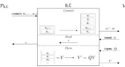
hP(s)←→ Vchan (t)i=bdepending on whether he accepts (b= 1) or rejects (b= 0). In thestandard channel ←→, all messages are forwarded between prover and verifier. As in [BCG+17], we also consider an ideal linear commitment channel,
ILC
←→, described in Figure 2. When using theILCchannel, the prover can submit
acommitcommand to commit to vectors of field elements of some fixed length
k, specified in the public parameters. The vectors remain secretly stored in the channel, and will not be forwarded to the verifier. Instead, the verifier only learns how many vectors the prover has committed to. The verifier can submit a send command to theILCchannel to send a mesage to the prover. In addition, the verifier can also submitopenqueries to theILCchannel to obtain openings of linear combinations of the vectors sent by the prover. We stress that the verifier can request several linear combinations of stored vectors within a single open query, as depicted in Figure 2 using matrix notation.
We say a proof system ispublic coin if the verifier’s messages to the com-munication channel are chosen uniformly at random and independently of the actions of the prover, i.e., the verifier’s messages to the prover correspond to the verifier’s randomness ρ. All our proof systems will be public coin. In a proof system over the ILC channel, sequences ofcommit,send andopen queries can alternate arbitrarily. However, since our proof systems are public coin we can without loss of generality assume the verifier will only make one bigopenquery at the end of the protocol and then decide whether to accept or reject.
LetRbe an efficiently decidable relation of tuples (pp, u, w). We can define a matching language L = {(pp, u)|∃w : (pp, u, w)∈ R}. We refer to uas the
PILC VILC
Fig. 2: Description of theILCchannel.
contain parameters that do not influence membership of R but may aid the prover and verifier, for instance the field and vector size in theILCchannel.
The protocol (K,P,V) is called a proof of knowledge over a communication channel←→chan for a relationRif it has perfect completeness and computational knowledge soundness as defined below.
Definition 1 (Perfect Completeness). A proof system is perfectly complete
if for all PPT adversaries A
Pr "
pp← K(1λ); (u, w)← A(pp) :
(pp, u, w)∈ R ∨ hP/ (pp, u, w)←→ Vchan (pp, u)i= 1 #
= 1.
Definition 2 (Knowledge soundness). A public-coin proof system has
com-putational (strong black-box) knowledge soundnessif for all DPTP∗ there exists an expected PPT extractorE such that for all PPT adversariesA
Pr "
pp← K(1λ); (u, s)← A(pp);w← EhP∗(s)←→Vchan (pp,u)i(pp, u) : b= 1 ∧ (pp, u, w)∈ R/
#
≈0.
Here the oracle hP∗(s) ←→ Vchan (pp, u)iruns a full protocol execution and if the proof is successful it returns the transcripttransP of the prover’s communication with the channel. The extractor E can ask the oracle to rewind the proof to any point in a previous transcript and execute the proof again from this point on with fresh public-coin challenges from the verifier. We let b∈ {0,1} be the verifier’s output in the first oracle execution, i.e., whether it accepts or not, and we think of sas the state of the prover. The definition can then be paraphrased as saying that if the prover in state smakes a convincing proof, then E can extract a witness.
If the definition holds also for unbounded P∗ and A we say the proof has
statistical knowledge soundness.
We will construct public-coin proofs of knowledge that have special honest-verifier zero-knowledge. This means that if the verifier’s challenges are known in advance then it is possible to simulate the verifier’s view without knowing a witness. In our definition, the simulator works even for verifiers who may use adversarial biased coins in choosing their challenges as long as they honestly follow the specification of the protocol.
Definition 3 (Special Honest-Verifier Zero-Knowledge). A public-coin
proof of knowledge is computationally special honest-verifier zero-knowledge (SHVZK) if there exists a PPT simulatorS such that for all stateful interactive PPT adversaries Athat output (u, w)such that(pp, u, w)∈R and randomness ρfor the verifier
Pr "
pp← K(1λ); (u, w, ρ)← A(pp);
viewV ← hP(pp, u, w)
chan
←→ V(pp, u;ρ)i:A(viewV) = 1
#
≈Prpp← K(1λ); (u, w, ρ)← A(pp);viewV← S(pp, u, ρ) :A(viewV) = 1.
We say the proof isstatistically SHVZKif the definition holds also against un-bounded adversaries, and we say the proof is perfectly SHVZKif the probabilities are exactly equal.
Full Zero-Knowledge SHVZK only guarantees the simulator works for honest
verifiers. It is in some applications desirable to have full zero-knowledge where the simulator works for arbitrary malicious verifiers, even those that deviate from the protocol. However, it makes sense to simply focus on SHVZK since there are very efficient standard transformations from SHVZK to full zero-knowledge.
In the Fiat-Shamir transform [FS86] the verifier’s challenges in a proof system are computed using a cryptographic hash function applied to the transcript up to the challenge. The Fiat-Shamir transform can therefore make a public-coin proof system non-interactive. Our proof system is such that the Fiat-Shamir heuristic yields a non-interactive proof that is knowledge sound and has full zero-knowledge in the random oracle model.
If the random oracle model is undesirable, an alternative is to use coin-flipping between the prover and verifier to decide on the challenges. We let the public parameters include a trapdoor commitment scheme. The prover commits to coins
δ1, . . . , δµ and starts executing the proof system, where in roundiwith challenge
ρi from the verifier, the prover uses the modified challengeρ0i=ρi⊕δi. In the last round the prover then opens the commitment to δ1, . . . , δµ so the verifier learns the modifiers and hence what the challenges were. The idea is now that we give the simulator the trapdoor for the commitment scheme. This means it can simulate the proof with random public coin challenges ρ0i, and then at the end after seeing the verifier challengesρi open the commitments to suitable
2.3 TinyRAM
TinyRAM is a random-access machine model operating on W-bit words and usingK registers. We now describe the key features of TinyRAM but refer the reader to the specification [BSCG+13] for full details. A state of the TinyRAM machine consists of a programP (list of Linstructions), a program counterpc
(word), Kregistersreg0, . . . ,regK−1(words), a condition flagflag(bit), andM words of memory with addresses 0, . . . , M−1.
The TinyRAM specification includes two read-only tapes to retrieve its inputs but with little loss of efficiency we may assume the program starts by reading the tapes into memory5 We will therefore skip the reading phase and assume the memory is initialized with the inputs (and 0 for the remaining words). Also, we will assume on initialization thatpc,the registers andflagare all set to 0.
The program consists of a sequence ofLinstructions that include bit-wise logical operations, arithmetic operations, shifts, comparisons, jumps, and storing and loading data in memory. The program terminates by using a special command
answerthat returns a word. We consider the program to have succeeded if it
answers 0, otherwise we consider the answer to be a failure code.
We writeregiandriwhen referring to registeriand to its content, respectively. We write A to refer to either a register or an immediate value specified in a program instruction and writeAfor the value stored therein. Depending on the instruction a wordamay be interpreted as an unsigned value in{0, . . . ,2W −1} or as a signed value in {−2W−1, . . . ,2W−1−1}. Signed values are in two’s complement, so given a word a= (aw−1, . . . , a0)∈ {0,1}W the bitaW−1 is the sign and the signed value is −2W +a if a
W−1 = 1 and a if aW−1 = 0. We distinguish operations over signed values by using subscripts, e.g. a×sband
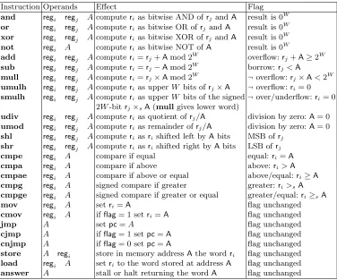
a≥sbare used to denote product and comparison over the signed values. With this notation in mind, we specify the instruction set in Table 1.
Correct Program Execution. It is often important to check that a protocol
participant supposedly running programP on public inputxand private input
w provides the correct outputz. Without loss of generality, we can formulate the verification as an extended program that takes public inputv= (x, z) and answers 0 if and only ifzis the output of the computation. We therefore formulate correct program execution as the program just answering 0.
We now give a relation that captures correct TinyRAM program execution. An instance is of the formu= (P, v, T, M), whereP is a TinyRAM program,v
is a list of words given as input to the program,T is a time bound, andM is the size of the memory. A witnesswis another list of words. We assume without loss of generality that the witness is appended by 0’s, such that|v|+|w|=M and the program starts with the memory being initialized to these words.
The statement we want to prove is that the programP terminates inT steps usingM words of memory on the public inputv and private inputwwith the
5
Instruction Operands Effect Flag
and regi regj Acomputerias bitwise AND ofrj andA result is 0W
or regi regj Acomputerias bitwise OR ofrjandA result is 0W
xor regi regj Acomputerias bitwise XOR ofrjandA result is 0W
not regi A computerias bitwise NOT ofA result is 0W
add regi regj Acomputeri=rj+Amod 2W overflow:rj+A≥2W
sub regi regj Acomputeri=rj−Amod 2W borrow:rj<A
mull regi regj Acomputeri=rj×Amod 2W ¬overflow:rj×A<2W
umulh regi regj Acomputerias upperW bits ofrj×A ¬overflow:ri= 0 smulh regi regj Acomputerias upperW bits of the signed¬over/underflow:ri= 0
2W-bitrj×sA(mullgives lower word)
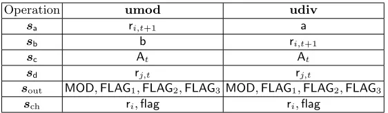
udiv regi regj Acomputerias quotient ofrj/A division by zero:A= 0
umod regi regj Acomputerias remainder ofrj/A division by zero:A= 0
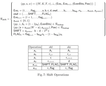
shl regi regj Acomputeriasrishifted left byAbits MSB ofrj
shr regi regj Acomputeriasrishifted right byAbits LSB ofrj
cmpe regi A compare if equal equal:ri=A
cmpa regi A compare if above above:ri>A
cmpae regi A compare if above or equal above/equal:ri≥A
cmpg regi A signed compare if greater greater:ri>sA
cmpge regi A signed compare if greater or equal greater/equal:ri≥sA
mov regi A setri=A flag unchanged
cmov regi A ifflag= 1 setri=A flag unchanged
jmp A setpc=A flag unchanged
cjmp A ifflag= 1 setpc=A flag unchanged
cnjmp A ifflag= 0 setpc=A flag unchanged
store A regi store in memory addressAthe wordri flag unchanged
load regi A setri to the word stored at addressA flag unchanged
answer A stall or halt returning the wordA flag unchanged
Table 1: TinyRAM instruction set, excluding thereadcommand. The flag is set equal to 1 if the condition is met and 0 otherwise. If thepcexceeds the program length, i.e.,pc≥L, or we address a non-existing part of memory, i.e., in astore
instructionanswer0. We therefore define
RTinyRAM=
(pp, u, w) = ((W, K,∗),(P, v, T, M), w)
P is a TinyRAM program withW-bit words,K registers, andM words of addressable memory, which on inputsv andw
terminates inT steps with the instructionanswer0.
Our main interest is to prove correct execution of programs that require heavy computation so we will throughout the article assume the number of steps outweigh the other parameters, i.e., T > L+M, where L is the number of instructions in the program.
3
Arithmetization of Correct Program Execution
As a first step towards the realization of proofs for the correct execution of TinyRAM programs we translateRTinyRAM into a more amenable relation
in-volving elements in a finite field. Given a TinyRAM machine with word-sizeW
and a finite fieldF, we can in a natural way embed words into field elements by encoding a word a∈ {0, . . . ,2W −1} as the field elementa1
F = 1F+· · ·+ 1F (a times). We will use fields of characteristic p > 22W −2W−1 because then sums and products of words are less thanpand we avoid overflow in the field operations we apply to the embedded words.
We will encode the program, memory and states of a TinyRAM program as tuples of field elements. We then introduce a new relationRfield
TinyRAM consisting of
a set of arithmetic constraints these encodings should satisfy to guarantee the correct program execution. The relation will take instancesu= (P, v, T, M), and witnesseswconsisting of the encodings as well as a set of auxiliary field elements.
In this section we specify the structure of the witnessw and how the relation of correct program execution decomposes into simpler sub-relations. It will be the case that the encoding of the witness can be done alongside an execution of the program inO(L+M+T) field operations.
3.1 Witness Structure
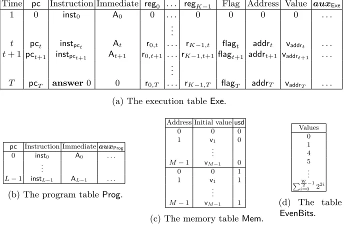
Given a correct program execution we encode program, memory and states of the TinyRAM machine as field elements and arrange them in a number of tables as pictured in Table 2. The execution table Exe, contains the field elements encoding of the states of the TinyRAM machine. It consists ofT rows, where row
tdescribes the state at the beginning of stept. A row includes field elements that encode the timet, the program counterpct, the instructioninstpct corresponding
topct, an immediate valueAt, the valuesr0,t, . . . ,rK−1,tcontained in the registers
reg0, . . . ,regK−1at timet, and the flagflagt. The next row contains the resulting state of the TinyRAM machine at timet+ 1. Each row also includes a memory addressaddrt, and the valuevaddrt stored at this address after the execution of
Time pc Instruction Immediate reg0 . . . regK−1 Flag Address Value auxExe
1 0 inst0 A0 0 . . . 0 0 0 0 . . .
. . .
t pct instpct At r0,t . . . rK−1,t flagt addrt vaddrt . . .
t+ 1 pct+1 instpct+1 At+1 r0,t+1 . . . rK−1,t+1flagt+1 addrt+1 vaddrt+1 . . .
. . .
T pcT answer0 0 r0,T . . . rK−1,T flagT addrT vaddrT . . .
(a) The execution tableExe.
pc Instruction ImmediateauxProg 0 inst0 A0 . . .
. . .
L−1 instL−1 AL−1 . . .
(b) The program tableProg.
Address Initial valueusd
0 0 0
1 v1 0
. . . M−1 vM−1 0
0 0 1
1 v1 1
. . . M−1 vM−1 1
(c) The memory tableMem.
Values 0 1 4 5 . . .
PW2−1
i=0 2 2i
(d) The table EvenBits.
Table 2: The execution table Exe, the program table Prog, the memory table
The next table is the program tableProg, which contains the field elements encoding of the TinyRAM programP. Each row contains the description of one line of the program, consisting of one instruction, at most three operands, and possibly an immediate value. Furthermore, we introduce a constant number of auxiliary field elements in each row. These entries can be efficiently computed given the program line stored in the same row and will help verifying its execution, e.g. we encode the position of input and output registers as auxiliary field elements. The memory tableMemhas rows that list the possible memory addresses, their initial values, and an auxiliary field elementusd∈ {0,1}. For every pair of address and corresponding initial value, the memory table Memcontains a row in whichusd= 0 and another row in whichusd= 1. Recall that the memory is initialized with input words listed inv, w, i.e., the input words contributing to the instance and witness of the relationRTinyRAM.
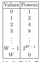
In addition to these, we also consider an auxiliary lookup table EvenBits
containing the encoding of words of lengthW whose binary expansion has 0 in all odd positions. The table contains 2W2 field elements and will be used as part
of a check that certain field elements encode a word of lengthW.
Let (Exe,Prog,Mem,EvenBits) be the tuple of field elements encoding the program execution and the auxiliary values. We can now reformulate the correct execution of a TinyRAM program defined byRTinyRAM as a relation that imposes
a number of constraints the field elements should satisfy:
Rfield TinyRAM=
(pp, u, w) = ((W, K,F,∗),(P, v, T, M),w)
w= (Exe,Prog,Mem,EvenBits,∗) (pp,(P, v, T, M),w)∈ Rcheck
(pp,(T, M),w)∈ Rmem
(pp,⊥,w)∈ Rstep
where the relationsRcheck,Rmem,Rstepjointly guarantee the witnessw consists
of field elements encoding a correct TinyRAM execution that answers 0 in T
steps usingM words of memory, public inputv, and additional private inputs. Specifically, the relationRcheck checks the initial values of the memory are
correctly included intoMem, the program is correctly encoded inProg,EvenBits
contains the correct encodings of the auxiliary lookup table, the initial state of the TinyRAM machine is correct and that it terminates with answer 0 in step
T. The role ofRmemis to check that memory usage is consistent throughout the
execution of the program. That is, if a memory value is loaded at time tthen it should match the last stored value at the same address. Finally,Rstepchecks
that each step of the execution has been performed correctly. In the rest of the section we describe each of these sub-relations, decomposing them in terms of elemental relations such as equality, lookup, and range relations.
Equality Relations.An equality relationReqcan be used to check that rows
Tabi of a tableTabencode tuples v1, . . . ,vmof givenW-bit words
Req=
(pp, u, w) = ((W, K,F,∗),(v1, . . . ,vm),Tab)
Lookup Relations.A lookup relation can be used to check membership of a tuple of field elementsw in the set of rows of a tableTab
Rlookup=
(pp, u, w) = ((W, K,F,∗),⊥,(w,Tab))
Tab={Tabi}i∧ ∃i:Tabi=w
We extend this relation in the natural way for checking the membership of multiple tuplesw1,w2, . . . in a table.
Range Relations.We will use a range relation to check that a field elementa
can be written as aW-bit word, i.e.,ais in the range{0, . . . ,2W −1}. One could use a lookup table of length 2W storing all values in the range and check thatais one of the entries in the table. However, this would give a table of size 2W which is too large. To get around this, we useae to store the integer corresponding to the even-position bits of the word stored in a, and for ao to store the integer corresponding to the odd-position bits ofa. For example, assume thatais a 4-bit valuea= (a3,a2,a1,a0) then we set its decomposition to be
ae= (0,a2,0,a0) ao= (0,a3,0,a1), such thata= 2ao+ae. LetEvenBitsbe the 2
W
2 word table storing all the words
where all the odd bit positions are zero. We can now check thatais in the range
{0, . . . ,2W −1}by checking thata= 2a
o+ae for ao,ae∈EvenBits. This gives us the following relation for a valueato be contained in a range{0, . . . ,2W−1}
Rrange=
(pp, u, w) = ((W, K,F,∗),⊥,(a,(ao,ae),EvenBits)) (pp,⊥,((ao,ae),EvenBits))∈ Rlookup ∧ a= 2ao+ae
.6
Permutation Relations. A permutation relation can be used to check that
two vectors are permutations of each other. The permutation is in the witness i.e. it is unknown to the verifier.
Rperm=
(pp, u, w) = (W, K,F,∗), T,({ai,bi,Tabi}Ni=1, π)
πis a permutation over{1, . . . , T} ∧π(ai) =bi
.
3.2 Checking the Correctness of Values
The role of Rcheck is to check that w consists of the correct number of field
elements that can be partitioned into the appropriate tables and also to check that specific entries in these tables are correct. In details, the relationRcheck is
specified by the following conditions
6
The relation can easily be extended to use decomposition intoκwords of length Wκ, thus reducing the size of the lookup table to|EvenBits|= 2Wκ. To get good efficiency
the important thing is to have 2Wκ T . In the article we assume for simplicity
2W2 T enabling us to useκ= 2 but our proof system can be modified to handle
– The first rowExe1 of the execution tableExecontains the following values: time is set equal to 1, the program counterpc1 is equal to 0, the instruction
instpc1 is equal to the first instruction of the program, the immediate valueA1
is the first immediate value of the program, and the contents of the registers
ri,1, the memory addressaddr1 and its content valuevaddr1 are all 0.
– The last rowExeT contains the following values: the time is set equal toT, the program counter ispcT =L−1, the instructioninstpcT isanswer, and
the immediate value is 0.
– The auxiliary lookup tableEvenBitscontains the embeddings of allW-bit words with 0 in all odd positions, i.e.
EvenBits=
0,1,4,5. . . ,
W 2−1
X
i=0 22i
– The program tableProgcontains the correct field element embedding of the programP as well as the correct auxiliary entries.
– The memory tableMemcontains the correct embedding of the input words listed inv and of the auxiliary entryusd.
We formalize these equality checks in the relation
Rcheck=
(pp, u, w) = ((W, K,F,∗),(P, v, T, M),w)
w= (Exe,Prog,Mem,EvenBits,∗),
Exe={Exet}Tt=1, Prog={Progi} L−1 i=0
Prog0= (0,inst0,A0, . . .)
(pp,(1,0,inst0, A0,0, . . . ,0, . . .),Exe1)∈ Req
(pp,(T,answer,0, . . .),ExeT)∈ Req
pp,0,1,4,5, . . . ,PW2−1
i=0 22i
,EvenBits∈ Req
(pp, P,Prog)∈ Req (pp, v,Mem)∈ Req
.
In the relationReq checking tableProgwe omitted the auxiliary entries which
we have not yet specified. It will later become clear that these entries can be efficiently computed given the programP and checked within the above relation.
3.3 Checking Memory Consistency
The relationRmem checks that the memory is used consistently across different
To help with checking the memory consistency, we include in each row of the execution table the following auxiliary entries
auxExe= τlinkvlinkvinitusd S L· · ·
where τlink contains the previous time-step at which the current address was accessed, unless this is the first time a location is accessed in which case it is set equal to the last time-step this location is accessed. Similarly, vlink stores the value contained in the address after timeτlink, unless this is the first time that location is accessed, in which case it stores the last value stored in that location. The valuevinitis a copy of the initial value assigned to that memory location, which is also stored in the memory tableMem. The valueusd is a flag which is set equal to 0 if this is the first time we access the current memory address, and 1 otherwise. The values S,Lare flags set equal to 1 in case the current instruction is astoreorload operation, respectively, and 0 otherwise. The valuesS,Lare also stored in the auxiliary entries of the program tableauxProg= S L· · ·.
We check memory consistency by specifying cycles of memory accesses, so that consecutive terms in a cycle correspond to two consecutive accesses to the same memory location. By using the above auxiliary entries, we use the relation
Rcyclefor the memory access pattern in the rows ofExe being in correspondence
with a permutationπ defined by such cycles. The relationRcycle checks that all
memory accesses (withS+L= 1) relative to the same address are connected into cycles and that rows not involving memory operations (S+L= 0) are not included in these cycles. The relation does not include any explicit checks on whetherS+Lis equal to 0 or 1. It is sufficient to check thatSt+Lt=St0+Lt0,
t=τlinkt0,vaddr
t =vlinkt0 andaddrt=addrt0, which ensures that operations which
are not memory operations are not part of cycles including memory operations.
Rcycle=
(pp, u, w) = ((W, K,F,∗), T,(Exe, π))
Exet= (t, . . . ,addrt,vlinkt, τlinkt, . . . , St, Lt, . . .)fort∈[T] a1={t}t∈[T],a2={addrt}t∈[T],a3={vaddrt}t∈[T],a4={St+Lt}t∈[T]
b1={τlinkt}t∈[T],b2={addrt}t∈[T],b3={vlinkt}t∈[T],b4={St+Lt}t∈[T]
((W, K,F,∗), T,({ai,bi}4i=1, π))∈ Rperm
The above relation only guarantees the existence of cycles over the same memory location, but it does not guarantee that consecutive terms in a cycle correspond to consecutive time-steps in which the memory is accessed. To check that the memory cycles are time-ordered we can simply verify thatt > τlinktfor any given time-step t∈[T]7. Since memory accesses are connected into cycles, the first time we access a new memory location the τlink entry stores the last point in time that location is accessed by the program. In this case (usd= 0), we verify thatt≤τlinkt. The relationRtime incorporates these conditions
Rtime=
(pp, u, w) = ((W, K,F,∗), T,Exe)
Exet= (t, . . . , τlinkt, . . . ,usdt, . . .) fort∈[T]
∀t∈[T] : (usd= 0∧t≤τlinkt)∨(usd= 1∧t > τlinkt)
7
Next, to ensure that the cycles correspond to sequences of memory addresses we also require that all the rows touching the same memory address are included in thesame cycle. Since the cycles are time-ordered, they require one time-step for whichusd= 0 in order to close a cycle. Thus, we can ensure each memory location to be part of at most on cycle by lettingusdto be set equal to 0 at most once for each memory address. We introduce abounded lookup relationRblookup
to address this requirement. The relation checks that for any row inExe, the tuple (addrt,vinitt,usd) is contained in one row of the tableMemand that each row (j,vj,0) of Memis accessed at most once by the program.
Rblookup=
(pp, u, w) = ((W, K,F,∗),(T, M),(Exe,Mem))
Exet= (t, . . . ,addrt, . . . ,vinitt,usdt, . . .) fort∈[T]
∀t∈[T] (pp,⊥,((addrt,vinitt,usdt),Mem))∈ Rlookup ∧ ∀ (j,vj,0)∈Mem: (. . . , j, . . . ,vj,0, . . .) occurs at most once in Exe
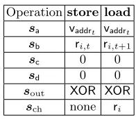
Finally, we are only left to check that if the program executes aload in-struction the valuevaddrt loaded from memory is consistent with the value stored
at the same address at the previous access. Similarly, ifloadis executed on a new memory location, then the value loaded should match with the initial value
vinitt. No additional checks are required forstoreinstructions. These checks are incorporated in the relationRload.
Rload=
(pp, u, w) = ((W, K,F,∗), T,Exe)
Exet= (t, . . . ,addrt,vaddrt, τlinkt,vlinkt,vinitt,usdt, . . .) fort∈[T]
∀t∈[T] :Lt(vaddrt−vinitt+usdt(vinitt−vlinkt)) = 0
Overall the memory consistency relationRmemdecomposes as follows
Rmem=
(pp, u, w) = ((W, K,F,∗),(T, M),w)
w= (Exe,Prog,Mem,EvenBits, π,∗),
Exe={Exet}Tt=1 Mem={Memj}2Mj=0−2 (pp, T,(Exe, π))∈ Rcycle, (pp, T,Exe)∈ Rtime
(pp,(T, M),(Exe,Mem))∈ Rblookup, (pp, T,Exe)∈ Rload
3.4 Checking Correct Execution of Instructions
We use the relationRstep to guarantee that each step of the execution has been
performed correctly. This involves checking for each rowExetof the execution table that the stored words are in the range{0, . . . ,2W −1}, the flag
To help checking the consistency of the operations the rows of the execution and program tables include the following auxiliary entries
auxExe= . . .a b c dout sa sb sc sdsout sch. . . auxProg = . . .sa sbsc sdsout sch
These consist of sometemporary variables a,b,c,d, an output vectorout, and some selection vectorssa, . . . ,schwhich are also listed in the program table.
The temporary variables are used to store a copy of the inputs and out-puts of an instruction. For example, if we have to check an addition operation
add regi regj A, we let c =ri,t+1,a =rj,t,b = At and check c= a+b. The advantage of the temporary variables is that for each addition operation we check, we will always have the inputs and output ina,b andc, instead of having to handle multiple registers holding inputs and output in arbitrary order.
Checking operations on temporary valuesa,b,canddrequire us to multiplex the corresponding register, immediate, and memory values in and out of the temporary values. We do this using selection vectorssa,sb,sc,sd that are
bit-vectors encoding the operands of an instruction. Each row of the execution table includes multiple variables that may be selected as an operand, e.g.,pct,At,r0,t, . . . and variables in the next row of the execution tablepct+1,At+1,r0,t+1, . . .may also be selected. A selection vector will have a bit for each of these variables indicating whether it is picked or not, so if we for instance letsa= (0,0,1,0, . . . ,0)
this corresponds to pickaas r0,t.
Multiplexing the operands into temporary variables leaves us with the task of checking correct instruction execution on a,b,c and d. TinyRAM has 26 instructions and since we want the proof system to be zero-knowledge, we cannot reveal which operation we execute in a given step. However, we can still obtain significant savings compared to using 26 independent instruction checkers. We make the key observation that many operations are closely re-lated. For instance checking a subtraction operation sub regi regj A corre-sponds to checking c = a +b with c = rj,t,a = ri,t+1,b = At, which is of the same form as an addition operation. Using clever multiplexing we re-duce the checking of the 26 possible instructions to 9 easily computable values
The relationRstepdecomposes into the following sub-relations over each pair
of consecutive rowsExet,Exet+1 in the execution table.
– A multiplexing relationRmux checking that valuesat,bt,ct,dt are consistent with operands contained ininstt.
– A consistency relationRconsistentchecking that the time counter is correctly
increased, the program counter is in the correct range, the instructioninstt and the immediate valueAt are consistent with the ones specified in linepct of the program, the correctness of the selector vectors, the entries inoutt relevant toinsttare all equal to zero and all registers are equal in the two rows unless specified by the instruction.
– An instruction checker relationRinschecking that entriesat,bt,ct,dtare in the range{0, . . . ,2W −1}, the vectorout
t is consistent withat,bt,ct,dt.
Rstep=
(pp, u, w) = ((W, K,F,∗),⊥,w)
w= (Exe,Prog,Mem,EvenBits,∗) ∧ Exe={Exet}Tt=1
∀t∈ {1, . . . , T −1}:
(pp,⊥,(Exet,Exet+1))∈ Rmux
(pp,⊥,(Exei,Exei+1,Prog))∈ Rconsistent
(pp,⊥,(Exei,Exei+1,EvenBits,∗))∈ Rins
Multiplexing Relation. The multiplexing relationRmuxchecks thata,b,c,d
match with the entries in the rows selected by the vectorssa,sb,sc,sd.
Let Exet = (pct,At,r0,t, . . . ,rK−1,t,flagt,addrt,vaddrt) be the tuples of
se-lectable entries of rowExet and letsat,sbt,sct,sdtbe binary vectors of length 2|Exet|. We can then express the multiplexing relation Rmux in terms of inner
product relations as follows
Rmux=
(pp, u, w) = ((W, K,F,∗),⊥,(Exet,Exet+1))
Exet= (t, . . . ,at,bt,ct,dt,outt,sat,sbt,sct,sdt, . . .)
at=sat· Exet||Exet+1
bt=sbt· Exet||Exet+1
ct=sct· Exet||Exet+1
dt=sdt· Exet||Exet+1
Consistency Relation.The consistency relationRconsistent is checks that the
time is correctly incremented and that the program counter is in the correct range, i.e.pct+1∈ {0, . . . , L−1}and is incremented unless a jump-instruction is executed. It also checks that the instruction, the immediate value and the selection vectors stored in the execution table are consistent with the program the line indexed pc. Furthermore, it checks that the entries inouttrelevant to
insttare all equal to zero and that the contents of the registers do not change, unless specified by the instruction, e.g. the register storing the result of the computation.
Letsch be a binary vector of lengthK+ 2, let gExet= (pct,r0,t, . . . ,rK−1,t,
|sout|=|out|= 13. The consistency relationRconsistentis defined as follows
Rconsistent=
(pp, u, w) = ((W, K,F,∗),⊥,(Exet,Exet+1,Prog))
Exet= (t,pct,instt,At, . . . ,r0,t, . . . ,rK−1,t, . . . ,St,Lt, . . . ,out,sa,sb,sc,sd,sout,sch)∧
Exet+1= (t0,pct+1, . . . ,r0,t+1, . . . ,rK−1,t+1, . . .)
t0=t+ 1 ∧ pc
t+1∈ {0, . . . , L−1} ∧
sch◦(Exegt+1−Exegt−(1,0, . . . ,0)) = (0,0, . . . ,0) ∧ sout◦out=0∧ (pp,⊥,((pct,instt,At,St,Lt,sa,sb,sc,sd,sout,sch),Prog))∈ Rlookup
Instruction Relation. The role of the instruction checker relationRins is to
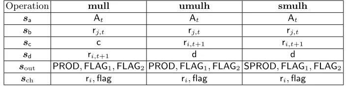
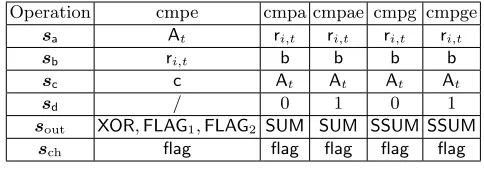
guarantee the correct execution of an instruction has taken place. We show that this can be reduced to check thata,b,c,d∈ {0, . . . ,2W−1}and that the output vectoroutis consistent with the temporary variables. We divide the entries ofout into 4 groups: logical (AND,XOR,OR), arithmetic (SUM,PROD,SSUM,SPROD,
MOD), shift (SHIFT), and flag (FLAG1,FLAG2,FLAG3,FLAG4). By specifying constraints to all these entries, we can directly verify all the logical, arithmetic, and shifts operations after which the variables are named. In Section 3.5 we show choices of selection vectors which reduce the verification of any other operation to the ones contained in these 3 categories.
TheRinscan be thus decomposed into 3 sub-relations.
Rins=
(pp, u, w) = ((W, K,F,∗),⊥,(Exet,Exet+1,EvenBits,∗)) (pp,⊥,(Exet,Exet+1,EvenBits))∈ Rlogic
(pp,⊥,(Exet,Exet+1,EvenBits))∈ Rarith
(pp,⊥,(Exet,Exet+1,EvenBits,∗))∈ Rshift
3.5 A Breakdown of the Instruction Relation
We describe the instruction checker relationRinsthat verifies correct execution of
an instruction in a given time-step. We recall that for each operation we multiplex inputs and outputs into temporary variablesa,b,c,dand use selection vectors sa,sb,sc,sdto ensure that this is done consistently with the the operands specified
by the instruction. Since our aim is to construct zero-knowledge arguments, the relationRinswill incorporate checks concerning all possible TinyRAM instructions
to hide which one was executed. We will show this can be reduced to 13 values stored in the output vector
out= (AND,XOR,OR,SUM,SSUM,PROD,SPROD,MOD,SHIFT,FLAG1,FLAG2,FLAG3,FLAG4)
Each instruction can be verified by checking that an entry of either the ofout are 0, using a selection vectorsout. Similarly, we use vectorschto check that the program counter, registers and flag do not change unless the instruction specifies so. Here we assume the selection vectors stored in each row of the execution table to be consistent with the instruction and immediate value stored in the same row ofExe, as already ensured by the relationRconsistent.
We decompose the relationRinsinto 3 sub-relations.
Rins=
(pp, u, w) = ((W, K,F,∗),⊥,(Exet,Exet+1,EvenBits,∗)) (pp,⊥,(Exet,Exet+1,EvenBits))∈ Rlogic
(pp,⊥,(Exet,Exet+1,EvenBits))∈ Rarith
(pp,⊥,(Exet,Exet+1,EvenBits,∗))∈ Rshift
In this section we describe all the sub-relations and reduce the verification of any operation to these by showing appropriate choices of selection vectors.
We recall that a line in the program consists of an instruction and up to three operands, e.g.addregi regj A. The first operand,regi, usually points to the register storing the result of the operation, add, computed on the words specified by the next two operands, regj, A. The last operandA indicates an immediate value that could be either used directly in the operation or to point to the content of another register. We refer to the value to be used in the operation generically asA, stressing that the selection between either the immediate value or a register value can be handled by using the appropriate selection vector.
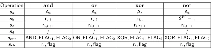
In what follows we specify what constraints the entries ofoutneed to satisfy and the appropriate choice of selection vectors for each operation. More precisely, which entriessa,sb,sc,sd,sout are set equal to 1 (with the rest set to 0) and which entries ofsch are set equal to 0 (with the rest set to 1).
Logical Operations Logical operations can be verified using the odd and even-position bits decomeven-position introduced in Section 3.1. Let a,bbe the inputs of a logical operation, e.g. bit-wise AND, and let cbe the output. To verify the correctness of the operation, e.g.a∧b=c, consider the decompositions of the inputs into their odd and even-position bits, namelya= 2ao+aeandb= 2bo+be.
Observe that taking the sum of the integers storing the even-positions ofa
andbgives
ae+be= (0,aW−2, . . . ,0,a0) + (0,bW−2, . . . ,0,b0)
= (aW−2∧bW−2,aW−2⊕bW−2, . . . ,a0∧b0,a0⊕b0)
The above contains the bit-wise AND and XOR of the even bits ofaandbplaced in even in odd positions, respectively. Therefore we can consider taking again the decomposition ofae+be into its odd and even-position bits, i.e.ae+be= 2eo+ ee so that half of the bits ofa∧bare stored in eo and half of the bits ofa⊕bare stored in ee. We can repeat the above procedure starting from the odd-position bits ofaand bgetting the following
ao+bo= (0,aW−1, . . . ,0,a1) + (0,bW−1, . . . ,0,b1)
= (aW−1∧bW−1,aW−1⊕bW−1, . . . ,a1∧b1,a1⊕b1) = 2oo+ oe
where oo stores half of the bits ofa∧band oe stores and half of the bits ofa⊕b. Putting everything together, given the decompositionsao,ae,bo,be,oo,oe,eo,ee∈
EvenBits, if the following hold
a= 2ao+ae b= 2bo+be
ao+bo= 2oo+ oe ae+be= 2eo+ ee then we also have
LetAND= 2oo+ eo−candXOR= 2oe+ ee−c. We can verify the execution of theand regi regj Asetting selection vectors so thata=At,b=rj,t,c=ri,t+1 and checking that AND= 0. Note that the latter is 0 if and only ifccontains the bit-wise AND ofaandb. Similarly, the execution ofxorregi regj Acan be verified by using the selector vectors as above and checking thatXOR= 0.
Givena∧b anda⊕b we can compute the bit-wise OR ofa and bin the following way
a∨b= (a∧b) + (a⊕b)
Let OR=XOR+AND+c. To verify the execution ofor regi regj A it is sufficient to set the selection vectors such that a=At,b= rj,t,c=ri,t+1 and check thatOR= 0, which happens if and only ifc=a∨b.
Bit-wise NOT can be handled by computing bit-wise XOR ofAwith the word 2W −1. We can use an additional auxiliary entry in the execution table storing the word 2W −1 and use the selector vector to route bto it. Similarly to the other logical operations, bit-wise NOT the same chek related to the flag, namely
FLAG1= 0,FLAG2= 0.
The execution of the above logical operations can also affect the flag. Specifi-cally, the flag is set equal to 1 exactly when the output is equal to 0. This can be verified by letting
FLAG1=flagt+1·c FLAG2= (flagt+1+c)·aflag−1
and checking both of them to be equal to 0. The first condition guarantees that at least one amongcandflagt+1 is zero, while the second guarantees that not both of them are equal to zero. In fact,FLAG2 can be made equal to 0 by choosing
aflag as the inverse offlagt+1+cunless their sum is 0.
We append the decompositions ofa,b,c,das well as oo,oe,eo,eeaflagto the
auxiliary entries of the execution table, i.e.
auxExe= . . .ao ae bobe co ce dode oo oe eoee aflag . . .
We now give theRlogic relation which includes all the above checks, as well as
the range checks on a,b,c,d.
Rlogic=
(pp, u, w) = ((W, K,F,∗),⊥,(Exet,Exet+1,EvenBits))
Exet= (t, . . . , . . . ,a,b,c,d,out, . . . ,ao,ae,bo,be,co,ce,do,de,eo,ee,oo,oe,aflag, . . .)
out= (AND,XOR,OR, . . . ,FLAG1,FLAG2, . . .)
Exet+1= (t+ 1, . . . ,flagt+1, . . .)
(pp,⊥,(a,(ao,ae),EvenBits)∈ Rrange (pp,⊥,(b,(bo,be),EvenBits)∈ Rrange (pp,⊥,(c,(co,ce),EvenBits)∈ Rrange (pp,⊥,(d,(do,de),EvenBits)∈ Rrange (pp,⊥,(ao+bo,(oo,oe),EvenBits)∈ Rrange (pp,⊥,(ae+be,(eo,ee),EvenBits)∈ Rrange
XOR= 2oe+ ee−c AND= 2oo+ eo−c OR=XOR+AND+c
FLAG1=flagt+1·c FLAG2= (flagt+1+c)·aflag−1
Operation and or xor not
sa At At At At
sb rj,t rj,t rj,t 2W−1
sc ri,t+1 ri,t+1 ri,t+1 ri,t+1
sd / / / /
sout AND,FLAG1,FLAG2OR,FLAG1,FLAG2XOR,FLAG1,FLAG2XOR,FLAG1,FLAG2
sch ri,flag ri,flag ri,flag ri,flag
Fig. 3: Logical operations
Integer Operations. Verifying integers operations is easier than logical opera-tions because we embed words as values in a field that is large enough to contain the sum and product of words, without causing overflowing.
The execution of an addition operationadd regi regj A can be verified by picking selection vectors such thata=At,b=rj,t,c=ri,t+1 and check that the following holds
a+b−c−2Wflagt+1= 0
Note that this is equal to 0 if and only ifccontains the result ofa+bwith the flagflagt+1 indicating overflow.
The same check can be used to verify a subtraction operationsubregiregj A
by swapping the role of the selection vector sb,sc and lettingb = ri,t+1 and
c = rj,t. The above equation is identically 0 if and only if b is equal to the difference ofcandawhere the flagflagt+1 denotes borrow.
LetSUM=a+b−c−2Wflagt+1+d. We can check the both additions and subtractions by lettingd= 0 and checking thatSUM= 0. While the temporary variable dis not strictly required for the verification of the above operations, we will see later that including this variable into the equation will make the verification of other operations easier.
Selection vectors for addition and subtraction are summarised in Figure 4.
Operation add sub
sa At At
sb rj,t ri,t+1
sc ri,t+1 rj,t
sd 0 0
sout SUM SUM
sch ri,flag ri,flag
Fig. 4: Addition and subtraction.