Available online: https://edupediapublications.org/journals/index.php/IJR/ P a g e | 2749
Z-Source Based Boost Dc-Dc Converter by Flyback and Voltage Multiplier
V.RAJASEKHAR1,S.BAJI 2N.HANUMA NAIK 3
1M.Tech Student, Dept of EEE, Sri Chundi Ranganayakulu Engineering College,Guntur, A.P, India.
2Associate Professor, Dept of EEE, Sri Chundi Ranganayakulu Engineering College,Guntur, A.P, India.
3Associate Professor&HOD,Dept of EEE, Sri Chundi Ranganayakulu Engineering College,Guntur, A.P, India
ABSTRACT:
At present in light of the contamination issues of the petroleum products, request of sustainable
power sources is expanded. Sun powered boards and energy components create low voltage,
subsequently high voltage step up dc-dc converters are expected to help their low yield voltage
to meet the inverters required voltage. Z-source converter has a few points of interest, for
example, high voltage step up, detached vitality source from the user side, clipped switch voltage
and positive yield voltage extremity, in this manner it is an appropriate decision for high advance
up applications. This paper presents a non-disengaged high advance up dc-dc converter which is
the induction of z-source converter and has a higher voltage pick up in contrast with the
traditional converters. This favorable position settles on this converter an appropriate decision
for photovoltaic applications. In addition, high lift voltage is gotten with low obligation cycle
and the vitality of spillage inductances is consumed so the effectiveness is expanded. A 100 W
research center model to change over 24-300 V is actualized to confirm the theoretical and
simulation results.
I. INTRODUCTION
The principle purpose for the over the
top carbon emanations is the intemperate
ignition of non-renewable energy
sources. Also, the ongoing instability of
the oil costs since 2014 has likewise
included a power behind the move from
non-renewable energy sources towards
the sustainable assets. Subsequently,ssil
Available online: https://edupediapublications.org/journals/index.php/IJR/ P a g e | 2750 Giant measures of carbon
dioxide are discharged into the
climate.
Carbon dioxide prompts nursery
impact or the worldwide warming.
Coal-consuming stations discharge
sulfur dioxide gas which causes to
corrosive rain.
Fossil energizes supplies are
restricted and are not sustainable.
Be that as it may, they create the low yield
voltage and the higher voltage is required
for inverters input, so the request of utilizing
high advance up dc-dc converters is
expanded. The regular arrangement was to
utilize the few PV cells in arrangement;
nonetheless, due to the module crisscross
andshadow impact of PV cells, the yield
control is diminished.
Principle points of interest of the proposed
converter can be consider:
The converter has high voltage step
up without expanding the turn
proportion of coupled inductors.
Four diodes of the converter are dead
under zero current exchanging (ZCS)
condition and two of them are turned
on under zero voltage exchanging
(ZVS) condition.
The invert recuperation issue of yield
diodes is wiped out.
High voltage pick up can be
accomplished for the low obligation
cycle. (D < 0:45)
Low pressure voltage of the
semiconductor gadgets (the switch
voltage is clipped).
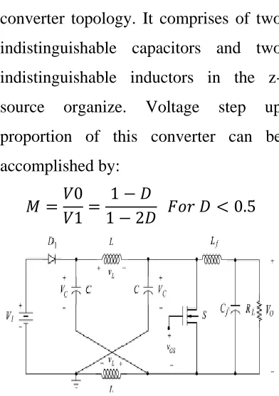
II. PROPOSED CIRCUIT
Figure 1 demonstrates the z-source dc-dc
converter topology. It comprises of two
indistinguishable capacitors and two
indistinguishable inductors in the
z-source organize. Voltage step up
proportion of this converter can be
accomplished by:
𝑀 =𝑉0
𝑉1 =
1 − 𝐷
1 − 2𝐷 𝐹𝑜𝑟 𝐷 < 0.5
Fig.1. Z-Source Converter Topology.
The proposed converter topology is
Available online: https://edupediapublications.org/journals/index.php/IJR/ P a g e | 2751
and voltage multiplier are utilized to
increment the voltage pick up of this
converter. It has two primary
working modes amid one exchanging
period in the steadystate. It is accepted
all the semiconductor gadgets are
perfect, the converter works in CCM.
The turn proportion of coupled inductors
is characterized by n = Ns/Np.
Fig2. Proposed Z-Source Converter Topology.
Mode 1:
This task mode is begun when dynamic
switch S is turned on. At that point the
information diode D1 is killed. So the
principle dynamic switch S and the
information diode of the proposed
converter work in the corresponding
way. At that point, the capacitors C
voltage is connected over the inductors
L1 and since this voltage is sure and
steady, inductors L1 current are
expanded directly and with a consistent
incline
.The turn proportion of the couple inductors
L1 and L2 is characterized as n = n2/ n1 in
this way, n times of the voltage crosswise
over inductors L1 is connected crosswise
over inductors L2. This causes the D2 and
D5 to be turned on. So the capacitors Co2
and Co5 are charged in this time interim.
At the point when the diodes D2 and D5
are turned on, the negative voltage is
connected crosswise over diodes D3 and
D4 and makes these diodes to be killed.
Since the channel inductor Lf voltage is
negative in this task mode, the inductor
current is diminished directly and it's
vitality is lost.
These sets of equations including inductors
voltage anddiodes stress voltage can be
written for this operation mode:
𝑉𝐿1 = 𝑉𝑐, 𝑉𝐿2 = 𝑛𝑉𝑐 … … . . (2)
𝑉𝐿𝑓 = −𝑉01 … … . . (3)
𝑉02 = 𝑉05 = 𝑉𝐿2 = 𝑛𝑉𝑐 … … . . (4)
𝑉𝐷1 = 2𝑉𝑐 − 𝑉1 … … . . (5)
Available online: https://edupediapublications.org/journals/index.php/IJR/ P a g e | 2752
This mode is begun when the turn S is killed.
At that point the voltage crosswise over it
continue expanding till the information diode
D1 is turned on. n times of L1 negative
voltage is instigated over inductors L2 and
after that diodes D3 and D4 are turned on and
diodes D2 and D5 end up off. So capacitors
Co3 and Co4 are charged. These
arrangements of conditions including
inductors voltage what's more, diodes and
switch pressure voltage can be composed for
this activity mode:
𝑉𝐿1 = 𝑉1 − 𝑉𝑐, 𝑉𝐿2 = 𝑛(𝑉1 − 𝑉𝑐) … … . . (6)
𝑉03 = 𝑉04 = −𝑉𝐿2 = 𝑛(𝑉𝑐 − 𝑉1) … … . . (7)
𝑉𝑠 = 2𝑉𝑐 − 𝑉1 … … . . (8)
𝑉𝐿𝑓 = 2𝑉𝑐 − 𝑉1 − 𝑉01 … … . . (9)
III.PERFORMANCE COMPARISON
PV boards more often than not have
ostensible voltage of 24 volts and energy of
100 watts. Additionally for 110 volts (rms)
AC of utility, 300 volts DC input voltage is
required for half-connect inverter also, for
220 volts (rms) AC of utility, 300 volts DC
input voltage is required for full-connect
inverter. If AC (rms) voltage of 120 Volts is
required at the inverter yield, half extension
inverter ought to be utilized with the
information DC voltage of 300 Volts. In
light of these realities, proposed dc-dc
converter is composed to change over 24
volts to 300 volts. In this segment, the
proposed converter is contrasted and other
dc-dc converters. the yield voltage of a 100
W PV board (24 volts DC) is changed over
to 120 volts AC with the control handling
unit . Thusly, a high advance up dc-dc
converter is expected to change over 24
volts DC to 300 volts DC for the half
extension inverter input. So the step up of
12.5 is required.
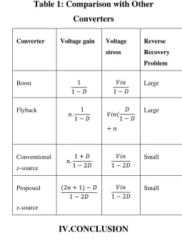
Table 1: Comparison with Other
Converters
Converter Voltage gain Voltage stress
Reverse Recovery Problem
Boost 1
1 − 𝐷
𝑉𝑖𝑛 1 − 𝐷
Large
Flyback
𝑛. 1
1 − 𝐷 𝑉𝑖𝑛(
𝐷 1 − 𝐷 + 𝑛
Large
Conventional
z-source
𝑛. 1 + 𝐷 1 − 2𝐷
𝑉𝑖𝑛 1 − 2𝐷
Small
Proposed
z-source
(2𝑛 + 1) − 𝐷 1 − 2𝐷
𝑉𝑖𝑛 1 − 2𝐷
Small
Available online: https://edupediapublications.org/journals/index.php/IJR/ P a g e | 2753
In this project, a novel high advance up
z-source dc-dc converter with fly back and
voltage multiplier is introduced. Inferred
conditions demonstrate that voltage step up
of traditional z-source converter is expanded
significantly. The proposed converter has
higher part check in contrast with other said
converters, be that as it may, it wipes out the
issue of unpredictability and incredible
obligation cycle in traditional high advance
up converters. In addition, low pressure
voltage, high effectiveness also, extensive
variety of voltage pick up by picking turn
proportion, make it a decent contender for
high advance up applications, such as
expanding low yield voltage of sun based
boards or other applications, for example,
most extreme power point following and
hang control in small scale matrix
applications
REFERENCES
[1] F. Z. Peng, "Z-source inverter," IEEE
Transactions on industry applications, vol.
39.
[2] A. Torkan, "Plan, reenactment and
execution of a high advance up z-source
dc-dc converter with flyback and voltage
multiplier," Master's proposition, Texas
A&M University, 2016.
[3] M. B. Shadmand, R. S. Balog, and H.
Abu-Rub, "Demonstrate prescient control of
pv sources in a savvy dc appropriation
framework: Maximum control point
following and hang control," IEEE
Transactions on Energy Change, vol. 29, no.
4, pp. 913– 921, 2014.
[4] M. Metry, M. B. Shadmand, R. S. Balog,
and H. A. Rub, "Mppt of photovoltaic
frameworks utilizing sensorless
current-based model prescient control," IEEE
Transactions on Industry Applications,
2016.
Veesa Rajasekhar was born
in the year 1987. Present He is Pursuing his
M.Tech(PE) in Sri Chundi Ranganayakulu
Engineering College, Ganapavaram.
Guntut(Dt.),A.P
Available online: https://edupediapublications.org/journals/index.php/IJR/ P a g e | 2754
1984. He obtained his B.Tech degree in
Electrical and Electronical Engineering from
Gayathri Vidya Parishad college of
Engineering. He has completed M.Tech in
Jawaharlal Nehru Technological University
,Hyderabad. Presently he is working as an
Associate Professor in Sri Chundi
Ranganayakulu Engineering ollege
College, Ganapavaram, Guntur(Dt.),A.P
N.HANUMA NAIK was
born in the year 1981. He obtained his
B.Tech degree in Electrical and Electronical
Engineering from Anil Neerukonda Institute
of Science and Technology. He has
completed M.Tech degree in St.Theresa
Institute of Technology.Presentlyhe is
working as a Head of the Department in Sri
ChundiRanganayakulu Engineering College,