AT&T 555-230-716
Issue 2
August 1994
Integrated Solution III
While reasonable effort was made to ensure that the information in this document was complete and accurate at the time of printing, AT&T cannot assume responsibility for any errors. Changes and/or corrections to the information contained in this document may be incorporated into future issues.
FEDERAL COMMUNICATIONS COMMISSION (FCC) STATEMENT
This equipment has been tested and found to comply with the limits for a Class A digital device, pursuant to Part 15 of the FCC rules. These limits are designed to provide reasonable protection against such interference when operated in a commercial environment. Operation of this equipment in a residential area is likely to cause interference in which case the user at his own expense will be required to take whatever measures may be required to correct the interference.
TRADEMARK NOTICE
UNIX is a registered trademark of UNIX System Laboratories, Inc., a subsidiary of Novell, Inc. AUDIX, DEFINITY and SYSTIMAX are registered trademarks of AT&T.
Voice Power and FAX Attendant System are trademarks of AT&T. Phillips is a registered trademark of the Phillips Screw Company.
HP and LaserJet are registered trademarks of Hewlett-Packard Company. Centronics is a registered trademark of Centronics Data Computer Corp. HackerTracker is a trademark of MOSCOM Corporation.
SECURITY
As a customer of new telecommunications equipment, you should be aware of the significant and growing problem of theft of long distance services by third parties, known commonly as “toll fraud.” It is particularly important that you understand and take appropriate steps to deal with this crime because under applicable tariffs, you will be responsible for payment of associated toll charges. AT&T can not be responsible for such charges and will not make any allowance or give any credit resulting from toll fraud.
ORDERING INFORMATION
To order copies of this manual:
Contact: Your AT&T Account Team or your AT&T Authorized Dealer. or
Call: AT&T at 1-800-432-6600 or
Write: AT&T Customer Information Center P.O. Box 19901
Indianapolis, IN 46219
1
Introduction
1-1■ Overview of the System ■ System Configuration
Port Requirements
■ Using This Guide
■ Conventions Used in This Guide ■ Related Documents
■ Training Materials ■ Getting Help
1-1 1-3 1-6 1-7 1-8 1-9 1-12 1-13
2
Installing the Hardware
■ Preparing for Installation
Selecting a Site for the System Required Tools
Equipment Inventory
Maintaining the Equipment Log Activity Checklist
Interconnection Overview Location of Connectors
■ Setting Up the Hardware Installing Additional Boards
Procedure 2-1: Install Voice Port (IVP) Boards Procedure 2-2: Install Fax Port (IFP) Boards Connecting Components
Procedure 2-3: Connect the Video Display Procedure 2-4: Connect the Keyboard
Contents
Connecting the IVP Board Voice Lines
Procedure 2-6: Connect IVP4 (4-Port) Boards Procedure 2-7a: Connect IVP6 (6-Port) Boards:
Using 885A Adapter
Procedure 2-7b: Connect IVP6 (6-Port) Boards Without 885A Adapter
Connecting the IFP Board Fax Lines
Procedure 2-8: Connect IFP2 (2-Port) Boards Procedure 2-9: Connect IFP4 (4-Port) Boards Connecting the DCP Board Digital Port Line
Procedure 2-10: Connect DCP Board Connecting Remote Maintenance
and CAS (SMDR) Ports
Procedure 2-11: Connect Remote Maintenance Device RMD-HS Mk IV
RMD-HS RMD
Connecting the CAS (SMDR) Port
Procedure 2-12A: Connect CAS (SMDR) Port (DCE Port, Within 1000 Feet)
Procedure 2-12B: Connect CAS (SMDR) Port (TN-726 Circuit Pack, Within 2000 Feet) Procedure 2-12C: Connect CAS (SMDR) Port
(TN-754 Circuit Pack, Within 5000 Feet)
■ Starting the Master Controller
Procedure 2-13: Supply Power to the Master Controller Procedure 2-14: Start the System
Procedure 2-15: Observe the Power On Self-Test (POST)
Procedure 2-16: Log Into IS III
Procedure 2-18: Procedure 2-19: Procedure 2-20: (If Applicable) Procedure 2-21: Procedure 2-22: Procedure 2-23: Procedure 2-24: (If Applicable) Test the Test the Initialize Test Test Run Run
■ Completing the Installation Customizing the System Making a Backup
the the
CAS (SMDR) port 2-41
Remote Access Port 2-41
the Printer Setup
2-42
Optional Printer 2-43
DCP Board and Port 2-44
Voice (IVP) Board Diagnostics 2-46 Fax Board (IFP) Diagnostics
2-47 2-48 2-48 2-48
3
Upgrading the Hardware
■ Preparing for Upgrade Tools Required
Procedure 3-1: Shut Down the UNIX System
Integrated Solution Systems Other Systems
■ Upgrading the Master Controller II+ Procedure 3-2: Open
the Master Controller II+ Procedure 3-3: Remove the
Card Securing Bracket Installing Additional Memory
in the Master Controller II+
Procedure 3-4: Remove Expansion Boards Procedure 3-5: install Memory SIMMs Completing Memory Installation
Contents
Procedure 3-7: Upgrade the Hard Disk
in the Master Controller II+ 3-13
Adding Expansion Boards
to the Master Controller II+ 3-16
Procedure 3-8: Install Expansion Boards 3-16
■ Upgrading the Master Controller III 3-18
Procedure 3-9: Open the Master Controller III 3-18 Procedure 3-10: Upgrade the Hard Disk
in the Master Controller III 3-20
Adding Expansion Boards to the
Master Controller III 3-24
Procedure 3-11: Add Expansion
Boards to the Master Controller III 3-24
■ Upgrading the MAP/5 3-27
Opening and Closing the System Unit 3-27
Procedure 3-12: Opening the System Unit 3-28 Procedure 3-13: Closing the System Unit 3-29
Upgrading the Hard Disk 3-30
Procedure 3-14: Removing the Auxiliary Housing 3-30
Procedure 3-15: Replacing the Auxiliary Housing 3-31 Procedure 3-16: Removing/Replacing
the Hard Drive Housing 3-33
Procedure 3-17: Removing/Replacing the Drive Housing 3-34 Procedure 3-18: Replacing the Hard Disk Drive 3-36
Adding Expansion Boards to the MAP/5 3-39
IVP Board Configuration 3-43
IVP Board Jumper Settings 3-44
Mixing IVP4 and IVP6 Boards 3-44
Changing IVP Board Type 3-44
Configuration of Previously Installed Boards 3-45
Setting Line Impedance Switch 3-46
Setting Address Switch 3-47
Procedure 3-20: Test the IVP Switch Settings 3-48 Procedure 3-21: Renumber Voice Channels 3-49
IFP2 Board Configuration 3-50
IFP4 Board Configuration 3-51
■ DCP Board Configuration 3-52
4
Adding and Removing IS III Applications
■ Adding IS Ill Applications Adding AUDIX Voice Power
Software Required Activity Checklist
Procedure 4-1: Install the Software
Procedure 4-2: Reboot the System
Procedure 4-3: Confirm AUDIX Voice Power Installation Adding FAX Attendant to AUDIX Voice Power
Software Required Activity Checklist
Procedure 4-4: Install the Software Procedure 4-5: Reboot the System
Procedure 4-6: Confirm FAX Attendant Installation
Contents
Adding AUDIX Voice Power/FAX Attendant Software Required
Activity Checklist
Procedure 4-7: Install the Software Procedure 4-8: Reboot the System
Procedure 4-9: Confirm AUDIX Voice Power/ FAX Attendant Installation
Adding FAX Attendant (Standalone)
Software Required Activity Checklist
Procedure 4-10: Install the Software Procedure 4-11: Reboot the System
Procedure 4-12: Confirm FAX Attendant Installation Adding Call Accounting System (CAS)
Software Required Activity Checklist
Procedure 4-13: Install the Software Procedure 4-14: Confirm CAS Installation Procedure 4-15: Complete CAS Implementation
■ Removing IS III Applications
4-21 4-21 4-21 4-21 4-29 4-29 4-31 4-31 4-31 4-31 4-39 4-40 4-41 4-41 4-41 4-41 4-48 4-49 4-50
5
Completing CAS Implementation
Procedure 5-1 A: Initial Installation
Alternate Procedure 5-1 B: Install the PBX/KTS Interfaces
Procedure 5-2: Install the City/State Diskette Procedure 5-3: Verify the SMDR Settings
Procedure 5-4: Install the Custom Rates (Sitegen) Diskette
Procedure 5-5: Edit Organization Screens
Procedure 5-10: Test HackerTracker Alarms
Procedure 5-11: Installing Update Diskette(s) 5-36
6
Recovering from Catastrophic Failures
■ Recovering from Hard Disk Failure Materials Required
Activity Checklist
Procedure 6-1: Replace the Hard Disk Procedure 6-2: Install UNIX and
IS Ill Platform Software
Restoring the Complete System from Tape Backup
Installing IS Ill Applications
■ Recovering From Data Corruption
Restoring the Complete System from Tape Restoring the Administrative Files from Diskette Restoring the Complete Voice System
from Tape Backup
6-1 6-2 6-2 6-2 6-3 6-4 6-7 6-15 6-20 6-20 6-24 6-27
7
Upgrading the Software
■ Upgrading to IS Ill Materials Required Activity Checklist
Procedure 7-1: Print out the Administration Reports for Each Application
Procedure 7-2: Back Up the Existing System Procedure 7-3: Shut Down the System
Contents
Procedure 7-7: Verify the Restored Files 7-15 Procedure 7-8: Verify the Passwords for the
General and Maintenance Mailboxes 7-16
Procedure 7-9: Shut Down the System 7-18
Procedure 7-10: Back Up the IS III System 7-19
■ Updating the IS III Platform Software 7-20
■ Updating IS III Applications 7-27
8
Maintaining IS III
■ Administering Passwords Changing a Password Deleting a Password
■ Administering an IS III System Remotely Logging into a Remote System Logging Out of a Remote System
■ Displaying the Applications Installed on the IS III System
■ Testing the Printer
■ Changing the Printer Setup
■ Accessing the System Boot/Shutdown Log ■ Refreshing the IS III Boot Diskette
8-1 8-2 8-2 8-5 8-8 8-8 8-9 8-10 8-12 8-15 8-17 8-21
9
Troubleshooting
■ General Troubleshooting General Failure Screen Discoloration Screen Failure (No Display) Keyboard Failure (No Response)
Error Messages
Software Error Messages System Error Messages
■ Correcting Error Conditions General Diagnostics IVP Board Diagnostics IFP Board Diagnostics Hard Disk Failure Main Board Failure Data Corruption
■ Displaying the Disk Usage Report
9-4 9-4 9-4 9-7 9-8
9-8 9-8 9-8 9-9
9-9 9-10
A
Appendix A: CAS Alarm Notification
A-1■ CAS and HackerTracker Alarms A-1
Alarm Strategy A-2
Suggested Defaults A-2
Voice Mail Messages A-3
B
Appendix B: Terminal Types
B-1■ IS III Terminal Types B-1
C
Appendix C: AT&T 570/571 and 473/474 Printer Setup
C-1■ AT&T 570/571 Printer C-2
Testing the 570/571 Printer C-2
Contents
1
Introduction
1-11-1. The Master Controller II+ 1-3
1-2. The Master Controller III 1-4
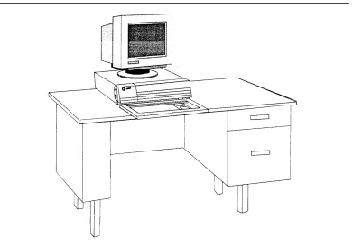
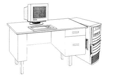
1-3. The Multi-Application Platform/5 1-4
2
Installing the Hardware
2-1. 2-2. 2-3. 2-4. 2-5. 2-6. 2-7. 2-8. 2-9. 2-10. 2-11. 2-12. 2-13. 2-14. 2-15. 2-16. 2-17. 2-18.
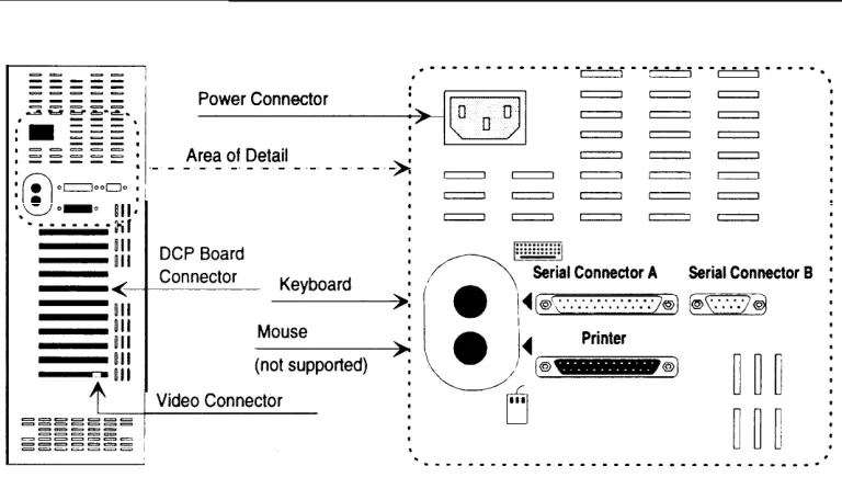
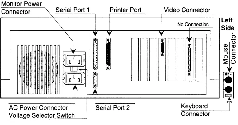
Equipment Interconnection Overview Master Controller II+ Connector Locations Master Controller III Connector Locations
MAP/5 Connector Locations (Desktop Configuration) MAP/5 Connector Locations (Tower Configuration) IVP4 Board with 884A Adapter for RJ11C
IVP6 Board with 885A Adapter for RJ11C IVP6 Board Direct Connection
IFP2 Board Connections for RJ11C
IFP4 Board with Two “Y” Cord Adapters for RJ11C DCP Board Connection
Remote Access and SMDR Port Connections RMD-HS Mk IV Connector Locations
RMD-HS Connector Locations RMD Connectors and Switches
CAS (SMDR) Connection to DCE Port Within 1000 Feet CAS (SMDR) Connection to TN-726 Circuit Pack
Within 2000 Feet
CAS (SMDR) Connection to TN-754 Circuit Pack Within 5000 Feet
2-1 2-7 2-8 2-9 2-10 2-11 2-17 2-18 2-19 2-20 2-21 2-22 2-23 2-25 2-26 2-27 2-29 2-31 2-33
3
Upgrading the Hardware
3-1. Master Controller II+ Cover Screws 3-2. Master Controller II+ Cover Removal 3-3. Removing Card Securing Bracket 3-4. Replacing Card Securing Bracket
3-1
Figures
3-8. 3-9. 3-10. 3-11. 3-12. 3-13. 3-14. 3-15. 3-16. 3-17. 3-18. 3-19. 3-20. 3-21. 3-22. 3-23. 3-24. 3-25. 3-26. 3-27. 3-28. 3-29. 3-30. 3-31. 3-32. 3-33. 3-34. 3-35. 3-36. Removing SIMMsMaster Controller II+ Internal Components Hard Disk Drive Bracket
Removing the Slot Cover Installing a Board
Side Panel Retaining Screw Locations Removing the Side Panel
Location of Hard Disk Drive Hard Disk Drive Mounting Rails Attaching Hard Disk Drive “L” Bracket Location of Expansion Board Slots
Removing the Slot Cover or Securing the Board Opening the MAP/5 System Unit
Removing Auxiliary Housing Replacing Auxiliary Housing
Removing/Replacing Hard Drive Housing Location of Drive Housing Locking Tabs Hard Disk Drive Tray Securing Screws Drive Tray
Standard Expansion Board Locations Removing Slot Cover
Installing or Removing Expansion Board IVP Board Identification
Address Switch Settings
Settings for SW1.1 (Old Layout Boards Only) Address Switch Settings
IFP2 Switch and Jumper Locations IFP4 Switch and Jumper Locations Location of Jumpers on DCP Board
2
Installing the Hardware
2-1 2-1. Integrated Solution III Maintenance Menu 2-372-2. Technician Maintenance Menu 2-38
2-3. Maintenance Log Menu 2-39
2-4. Display Installed Applications 2-40
2-5. Parallel Printer Port Setup 2-42
4
Adding and Removing IS III Applications
4-1. 4-2. 4-3. 4-4. 4-5. 4-6. 4-7. 4-8. 4-9. 4-10. 4-11. 4-12. 4-13. 4-14. 4-15. 4-16. 4-17. 4-18. 4-19. 4-20. 4-21. 4-22. 4-23. 4-24. 4-25. 4-26.
Integrated Solution III Maintenance Menu Technician Maintenance Menu
IS III Administration Confirmation Screen Administer Integrated Solution III Menu Confirm Applications Selected Menu
Select Release of System 75/DEFINITY Switch Menu integrated Solution III Maintenance Menu
Technician Maintenance Menu
IS III Administration Confirmation Screen Administer Integrated Solution III Menu Confirm Applications Selected Menu
Select Integrated Fax Processing Board Menu Integrated Solution III Maintenance Menu Technician Maintenance Menu
IS III Administration Confirmation Screen Administer integrated Solution III Menu Confirm Applications Selected Menu
Select Release of System 75/DEFINITY Switch Menu Select Integrated Fax Processing Board
Integrated Solution III Maintenance Menu Technician Maintenance Menu
IS III Administration Confirmation Screen Administer Integrated Solution III Menu Confirm Applications Selected Menu
Select Release of System 75/DEFINITY Switch Menu Select Integrated Fax Processing Board
Screens
4-30. Administer Integrated Solution III Menu 4-31. Confirm Applications Selected Menu 4-32. Menu Update Reminder Screen
4-33. Integrated Solution III Maintenance Menu 4-34. Technician Maintenance Menu
4-35. IS III Administration Confirmation Screen 4-36. Administer Integrated Solution III Menu
5
Completing
CAS
Implementation
5-1. Integrated Solution Call Accounting System Menu 5-2. Maintenance Log
5-3. CAS Alarm Configuration Screen 5-4. CAS Alarm Levels Screen
5-5. Sample CAS Alarm Configuration Screen
4-45 4-46 4-48 4-51 4-52 4-53 4-54 5-1 5-7 5-26 5-27 5-28 5-29
6
Recovering from Catastrophic Failures
6-16-1. 6-2. 6-3. 6-4. 6-5. 6-6. 6-7. 6-8. 6-9. 6-10. 6-11. 6-12. 6-13. 6-14. 6-15.
Select Master Controller Hardware Platform Menu Administer Integrated Solution III Menu
Integrated Solution III Maintenance Menu Technician Maintenance Menu
Restore Files Menu Restore Files Menu
Voice System Restore Menu
Select Release of System 75/DEFINITY Switch Menu Select Integrated Fax Processing Board Menu Confirm Applications Selected Menu
Technician Maintenance Menu Restore Files Menu
Restore Files Menu Restore Files Menu
Voice System Restore Menu
7
Upgrading the Software
7-1. 7-2. 7-3. 7-4. 7-5. 7-6. 7-7. 7-8. 7-9. 7-10. 7-11. 7-12. 7-13. 7-14.Select Master Controller Hardware Platform Menu Administer Integrated Solution III Menu
Select Release of System 75/DEFINITY Switch Menu Select Integrated Fax Processing Board Menu Confirm Applications Selected Menu
Technician Maintenance Menu
IS III Administration Confirmation Screen Administer Integrated Solution III Menu Confirm Applications Selected Menu Menu Update Reminder Screen Technician Maintenance Menu
IS III Administration Confirmation Screen Administer Integrated Solution III Menu Confirm Applications Selected Menu
7-1 7-7 7-8 7-9 7-10 7-11 7-21 7-22 7-23 7-24 7-26 7-27 7-28 7-29 7-30
8
Maintaining IS III
8-1. 8-2. 8-3. 8-4. 8-5. 8-6. 8-7. 8-8. 8-9. 8-10. 8-11.
Password Protection Menu
Change or Delete Password Menu Password Protection Menu
Change or Delete Password Menu Maintenance Log Menu
Maintenance Log Menu Confirm Printer Test Screen Parallel Printer Port Setup Screen Normal System Boot/Shutdown Log An Irregular System Boot/Shutdown Log Maintenance Log Menu
8-1 8-3 8-4 8-6 8-7 8-10 8-13 8-14 8-16 8-18 8-19 8-20
9
Troubleshooting
9-19-1. Maintenance Log 9-10
Introduction
Overview of the System
This manual is designed to assist AT&T field technicians and AT&T Authorized Dealers in installing and maintaining Integrated Solution III (IS III). This manual provides procedures for connecting major system components, adding application packages, customizing applications, recovering from catastrophic failure, and troubleshooting.
The System 75 and DEFINITY® Communications System Integrated Solution III1
consists of a Master Controller processor that is delivered to the customer with the UNIX® System V/386 Release 3.2.2 operating system, the IS III Platform Software, the application packages ordered by the customer, and the appropriate expansion boards already installed.2
You wiII, however, need to know how to install the system software in case the customer’s system experiences a hard disk crash, or if a
customer purchases an application to be installed after delivery of a pre-assembled system.
NOTE:
NOTE:
The Master Controller II+ is also known as the Applications Controller in some documentation.
NOTE:
AT&T FAX Attendant System™ is not supported on the Master Controller II+.
The IS III Platform Software is an “umbrella” program for the following software packages:
■ Integrated Solution Call Accounting System ■ AUDlX® Voice Power™
■ AT&T FAX Attendant System™
The IS III Platform Software is designed to do the following:
■ Assist with the installation, update, and customization of IS III applications. ■ Provide a single window for an end-user to access each application package
and any user-specific maintenance items.
■ Provide a single window for a Systems Technician to access each application package, user-specific maintenance items, and Systems Technician-specific maintenance items.
■ Provide a remote access capability to allow access to each application package and maintenance item from a remote location.
Introduction
System Configuration
The Master Controller’s main components are the system unit, the video display, the keyboard, and the remote maintenance device (not shown).
Introduction
The system unit contains the main board, internal peripherals, the power supply, and slots for expansion boards. Features of the Master Controller configured for use with IS III include:
■ A 20 MHz 80386SX CPU (MC II+), 20 MHz 80486SX CPU (MC III or 33 MHz 80486SX CPU (MAP/5)
■ A 100 or 200 MB hard disk (MC II+), 200 or 500 MB hard disk (MC III), or 210, 250, or 500 MB hard disk (MAP/5)3
■ A 1.44 MB diskette drive
■ 8 MB of onboard system Random Access Memory (RAM) ■ A video graphics adapter (VGA) controller
■ A built-in hard disk interface
■ A real-time clock/calendar with battery backup ■ Two available expansion slots (MC II+) or
five available expansion slots (MC III and MAP/5) ■ 128-Kbyte ROM (read-only memory) BIOS
■ Two built-in serial ports and one printer (parallel) port ■ A 125 MB tape drive (MC II+) or
250 MB tape drive (MC III and MAP/5)
The MC III or MAP/5 can run Integrated Solution Call Accounting System (IS CAS), AUDIX Voice Power, and FAX Attendant at the same time. The size of the hard disk drive (200 MB to 500 MB) and the number of voice (4 to 12) and fax (2 to 12) interface ports may limit the number of subscribers to the Voice and Fax Mail Services.
Port Requirements
Introduction
Using This Guide
The information in this guide is organized into nine chapters and three appendices:
Chapter 1, Introduction: This chapter offers an overview of Integrated Solution III (IS III) including basic components and software applications supported.
Chapter 2, Installing the Hardware: This chapter provides all information necessary to install the hardware platform for IS III.
Chapter 3, Upgrading the Hardware: This chapter provides all information necessary to upgrade the hardware platform for IS III.
Chapter 4, Adding and Removing IS III Applications: This chapter explains how to install each application package. It also explains how to remove applications.
Chapter 5, Completing CAS Implementation: This chapter describes how to complete the Call Accounting System implementation.
Chapter 6, Recovering from Catastrophic Failures: This chapter categorizes possible failure conditions and describes recovery procedures.
Chapter 7, Upgrading the Software: This chapter describes how to upgrade configurations to IS III, and how to update software to the latest release.
Chapter 8, Maintaining IS III: This chapter describes technician-level maintenance procedures that may be needed occasionally.
Chapter 9, Troubleshooting: This chapter describes common problems that may be encountered and how to rectify them.
Appendix A: CAS Alarm Notification: This appendix describes the parameters required to set the CAS alarms.
Appendix B: Terminal Types: This appendix describes the remote access terminal types that IS III supports.
Conventions Used in This Guide
The following conventions are used in this guide:
■ Commands and text that you should type appear as follows: Type this.
■ Values, instructions, and prompts that display on the screen appear as follows: Read this .
■ Keys that are always located in the same place on the PC keyboard appear in key-shaped boxes, as in [ENTER].
■ Key combinations (holding down one key while pressing another key) are connected with hyphens; for example: [CTRL] – [ALT] – [DEL].
■ Function keys that have changeable names appear in plain rectangular boxes, as in SAVE.
■ IS III and application software function keys (keys that start with an F, followed by a number) appear in boxes with the current meaning following in
parentheses, such as [F3] (SAVE).
The current meanings of the function keys are shown by labels at the bottom of the screen. On the actual screen, one of two sets of labels wiII appear:
— The first label is the meaning of the function key when the screen first appears. These meanings have been selected to be the most useful for that screen.
Introduction
Related Documents
You need to be familiar with the following documents:
■ AT&T Integrated Solution III
for System 75 and DEFINITY® Communications System System Manager’s Guide
Document No. 555-230-715
■ AT&T AUDIX™ Voice Power Release 2.1.1 System Manager’s Guide
Document No. 585-310-520
■ AT&T AUDIX™ Voice Power Release 2.1.1 User’s Guide
Document No. 585-310-521
■ AT&T AUDIX™ Voice Power Release 2.1.1 Planning Guide and Forms
Document No. 585-310-901
■ AT&T AUDIX™ Voice Power Release 2.1.1 Switch Notes
for System 75 Communications System Document No. 585-310-010
■ AT&T FAX Attendant System™ Release 2.1.1 User’s Guide
Document No. 555-007-102
■ AT&T FAX Attendant System™ Release 2.1.1 System Manager’s Guide
Document No. 555-007-100
■ AT&T FAX Attendant System™ Release 2.1.1 Planning and Forms
Document No. 555-007-101
■ AT&T FAX Attendant System™ Release 2.1.1 Implementation and Switch Notes
for System 75 and DEFINITY® Communications System Generic 1 and Generic 3
■ AT&T Diagnostic Program User’s Guide Document No. 560-407-151
■ AT&T Applications Controller User’s Guide Document No. 585-249-710
■ AT&T Master Controller III User’s Guide Document No. 560-407-150
■ AT&T Multi-Application Platform/5 User’s Guide Document No. 585-211-110
■ AT&T MAP/5 Diagnostic Program User’s Guide Document No. 585-211-111
■ AT&T Call Accounting System (CAS) Integrated Solution II Planning Guide and Forms
Document No. 585-247-050
■ AT&T Call Accounting System (CAS) integrated Solution II Site Installation and Implementation Guide
Document No. 585-247-010
■ AT&T Call Accounting System (CAS) Integrated Solution User’s Guide
Document No. 585-247-120
■ AT&T Call Accounting System (CAS) Integrated Solution Quick Reference Card
Document No. 585-247-121
■ HackerTracker™ for Integrated Solution Call Accounting System
Introduction
■ AT&T System 75 Implementation Manual, Release 1, Version 3 Document No. 555-200-652, Issue 3
■ AT&T DEFINITY® Communications System Generic 1 and System 75 and System 75XE
Administration and Measurement Reports Document No. 555-200-500, issue 5
■ AT&T DEFINITY® Communications System Generic 1 and Generic 3 System Management
Document No. 555-230-500, Issue 1, January, 1992
Document No. 555-230-500ADD, Addendum 1, September, 1992 Document No. 555-230-500ADD2, Addendum 2 for DEFINITY G3vs,
March, 1993
■ AT&T DEFINITY® Communications System Generic 3i Implementation
Document No. 555-230-650, Issue 1, January, 1992
Document No. 555-230-650ADD, Addendum 1, September, 1992 Document No. 555-230-650ADD2, Addendum 2, March 1993
Document No. 555-230-650ADD3, Addendum 3 for DEFINITY G3vs, March, 1993
■ AT&T DEFINITY® Communications System Generic 1 and Generic 3i System Reports
Document No. 555-204-510
■ AT&T DEFINITY® Communications System Generic 3r System Reports
Training Materials
Technical product training is available to AT&T technical associates. The following Individualized Learning Programs (ILPs) are available for DEFINITY IS III:
■
■
■
DEFINITY IS III Platform Course Number: S09223W
Document Number: GBCS-1800-PLT
AUDIX Voice Power, Rel 2.1.1, for DEFINITY IS III Course Number: S09103W
Document Number: GBCS-1800-AVP DEFINITY IS CAS and HackerTracker Course Number: S09111Y
Document Number: GBCS-1800-CAS
Introduction
Getting Help
This chapter provides information for setting up a new installation. For upgrade procedures, see Chapter 3, “Upgrading the Hardware,” and Chapter 7, “Upgrading the Software. ”
The Master Controller comes loaded with IS III and all of the ordered software applications when shipped from AT&T. Even though all of the software is loaded, a boot disk and tape copy of the software are also supplied to use in case of
catastrophic failure.
This chapter includes the following information on setting up the system:
■ Preparation
■ Required tools and equipment
■ Specific procedures for setting up, connecting, and checking the system
Preparing for Installation
Before you begin installing the hardware, you should complete the following tasks that are detailed in this section:
■ Select an appropriate site for the system. ■ Collect the necessary tools.
■ Verify that all ordered equipment is on-site.
Installing the Hardware
Selecting a Site for the System
The Master Controller can be used in a variety of environments.
N O T E :
References to the Master Controller apply to the Master Controller II+, the Master Controller III, or the MAP/5. Any information that differs among the three processors will be noted specifically. The Master Controller II+ is also described as the Applications Controller in some documentation.
To insure proper system operation, the Master Controller must be located in an area that meets all of the following requirements:
■ The Master Controller must be connected to a grounded power outlet. Ungrounded machines may be harmed by static electricity, may fail to work properly, and can be a safety hazard. Improper program execution,
unreadable disks, and extensive machine damage can result.
■ The area must be clean and dust free. Airborne dust, dirt, copy machine toner, and smoke can cause excessive wear on the disks and read/write errors.
■ The installation site must be well-ventilated and away from heat sources. Excessive heat and direct sunlight can cause undesirable conditions such as low humidity, which can cause static problems.
■ The Master Controller must be isolated from strong electromagnetic fields produced by electrical devices (for example, air conditioners, large fans, large electric motors, radio and television transmitters, and high-frequency security devices).
■ The Master Controller must be installed away from water and excessive humidity.
Required Tools
Make sure you have the proper tools ready:
■ 3/16“ flat-blade screwdriver ■ #1 Phillips® head screwdriver ■ 3/16“ nut driver
■ an antistatic grounded wrist strap ■ an antistatic grounded work mat
DANGER:
The system unit power supply contains AC voltage at levels that can cause injury or death on contact. Before removing any system unit covers, turn off the system and unplug the power cord from the AC outlet.
CAUTION:
Installing the Hardware
Equipment Inventory
Verify that all ordered and shipped equipment is on the premises and not damaged in any way. Unpack the system components from the boxes and make sure they are in good condition. Check for the following:
❑ ❑ ❑ ❑ ❑ ❑ ❑ ❑ ❑ ❑ ❑ ❑ ❑ ❑ ❑ ❑ ❑
Master Controller system unit:
■ Master Controller II+ (desktop) ■ Master Controller III (tower) ■ M A P / 5
Two keys for system unit chassis lock System unit power cord
Video display and cables Keyboard with cable
Two-outlet surge protector with power strip Diagnostic diskette
Utility diskette (MC II+ and MC III only) Equipment Log form
Two blank tape cartridges IS III Boot Diskette IS III Installation Tape
RMD or RMD-HS with power supply and modular cable Switch box kit with:
❑ A/B switchbox (not used) ❑ M-M gender changer ❑ 25-pin M-F cable ❑ 25-pin M-M cable
9-pin to 25-pin adapter
For CAS (SMDR) connection (provided only if CAS ordered): ❑ 355AF adapter
❑ D8W-87 8-conductor modular cable ❑ 355A adapter
❑ Optional printer with cables (power and data)
■ AT&T Applications Printer (wide carriage)
■ AT&T Call Accounting System Printer (narrow carriage) ■ HP® LaserJet® Series II compatible printer
❑ The following documents:
❑ AT&T Integrated Solution III for System 75 and DEFINITY® Communications System Installation and Maintenance (this guide)
❑ AT&T Integrated Solution III for System 75 and DEFINITY® Communications System System Manager’s Guide
❑ AT&T Master Controller III User’s Guide (MC III) or AT&T Applications Controller User’s Guide (MC II+) or AT&T Multi-Application Platform/5 User’s Guide (MAP/5)
❑ AT&T Diagnostic Program User’s Guide (MC II+ and MC III) or AT&T MAP/5 Diagnostic Program User’s Guide (MAP/5)
❑ AT&T 14-inch VGA Monitor User’s Guide
❑ Printer Guide (optional) ❑ Applications documents
Check the system unit, video display, and keyboard. Make sure all associated cables and power cords are present. If voice port (Integrated Voice Power™ (IVP4 or IVP6)) boards are included, verify that the correct number have been installed. If fax port (Integrated Fax Processing (IFP2 or IFP4)) boards are included, verify that the correct number have been installed. A set of matching keys is provided with the system unit to operate the mechanical chassis lock. (Tell the customer to keep the keys in a secure place.)
Maintaining the Equipment Log
Installing the Hardware
Activity Checklist
The system should be set up in the following order: 1. 2. 3. 4. 5. 6. 7. 8. 9. 10. 11. 12. 13. 14. 15. 16. 17. 18. 19. 20. 21. 22. 23. 24.
Configure and install any additional voice port (IVP) boards. Configure and install any additional fax port (IFP) boards. Connect the video display to the system unit.
Connect the keyboard to the system unit. Install the printer (if one is being used). Connect the voice port boards to analog ports.
Connect the fax port boards to analog ports if FAX Attendant is included. Connect the DCP board to a digital port.
Connect the remote access device to an analog port or an outside line. Connect the CAS (SMDR) ports on the Master Controller and the switch if CAS is included.
Supply power to the Master Controller and video display. .
Turn on the system.
Observe the Power On Self Test (POST). Log into IS III.
Make sure that the proper software packages are installed.
Check CAS (SMDR) port connection if CAS is included. Check remote access port connection.
Initialize printer setup (if applicable). Test the optional printer.
Test the DCP board and port.
Run voice port board (IVP) diagnostics.
Run fax port board (IFP) diagnostics (if applicable).
Perform additional switch administration or application customization (as applicable).
Interconnection Overview
Installing the Hardware
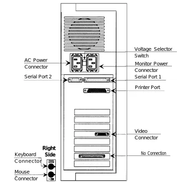
Location of Connectors
Refer to these figures as you connect the components together.
The connectors for the Master Controller II+ are on the rear and left side. The connectors are shown in Figure 2-2:
shown in Figure 2-3:
Installing the Hardware
The connectors for the MAP/5 are on the rear and on one side (left for desktop, for tower) near the front. The connectors are shown in Figure 2-4 (desktop) and Figure 2-5 (tower).
right
AC Power Connector
Serial Port 2
Right
Keyboard
Side
C o n n e c t o r
Mouse Connector
Voltage Selector Switch
Monitor Power Connector Serial Port 1
Printer Port
Video Connector
No Connection
Installing the Hardware
Setting Up the Hardware
When you have selected the proper site, gathered all required tools, and checked the components, you are ready to set up the system. To prevent damage from electrostatic discharge, remember to take precautions in handling, packing, and storing circuit packs; and remember to ground yourself.
Procedures for upgrading hardware are given in Chapter 3.
Installing Additional Boards
Procedure 2-1: Install Voice Port (IVP) Boards
All systems are shipped preconfigured with the necessary expansion boards installed. It is necessary to install additional expansion boards only when:
■ the customer has IVP boards from an existing system
■ IVP boards are being added to the configuration after shipping
The procedures for opening and closing the Master Controller system unit, and for identifying and installing IVP4 and IVP6 boards are given in Chapter 3, “Upgrading the Hardware. ”
Procedure 2-2: Install Fax Port (IFP) Boards
Connecting Components
Procedure 2-3: Connect the Video Display
To connect the video display, follow these steps:
1. Connect the video display cable to the connector on the system unit with the same size shell and the same number of pins. The connector has three rows totaling 15 pins. The other, similarly sized connector on the system unit has two rows totaling 9 pins. Connector locations are shown in Figure 2-2, Figure 2-3, Figure 2-4 and Figure 2-5.
2. Tighten the screws that hold the connector in place. Do not over tighten. 3. Attach the video-display power cord to the power socket on the back of the
video display.
4. Connect the other end of the power cord to the surge protector/power strip or to the Master Controller (see note).
NOTE:
All MAP/5 system units and some Master Controller II+ system units have a power connector for the monitor immediately above the power connector for the system unit. In this case, an alternate power cord for the monitor is shipped with the system unit. This alternate power cord should be used instead of the cord shipped with the monitor. The monitor power outlet on the system unit is controlled by the system unit power switch. This allows you to turn on the system unit and video display from a single switch.
NOTE:
If you turn on the monitor when the system unit is off, the power
indicator may light (if the monitor connects directly to the AC outlet), but the screen will remain blank.
NOTE:
Installing the Hardware
Procedure 2-4: Connect the Keyboard
Connect the keyboard by inserting the keyboard cable plug into the socket on the system unit. The keyboard cable plug has an indent in the metal shell (called a keyway) that is used to align the plug with the socket.
— On the Master Controller II+, the socket for the keyboard connector is located on the left side at the bottom. Refer to Figure 2-2. The keyway should face upward.
— On the Master Controller Ill, the socket for the keyboard connector is located on the rear. It is the upper of two similar connectors. Refer to Figure 2-3. The keyway should face upward.
— On the MAP/5, in the desktop configuration, the socket for the keyboard connector is located on the left side at the bottom. Refer to Figure 2-4. On the MAP/5, in the tower configuration, the socket for the keyboard connector is the upper of the two sockets located on the right side near the bottom of the system unit. Refer to Figure 2-5. In both cases, the keyway should face toward the front of the system unit.
Procedure 2-5: Install the Optional Printer
For installations that require fax printing, IS Ill supports any printer fully compatible with the HP® LaserJet® Series II. For installations that require printed reports, but not fax printing, IS Ill supports the AT&T Applications Printer (dot matrix, wide carriage) and the AT&T Call Accounting System Printer (dot matrix, narrow carriage).1
All printers must use a Centronics®-type parallel interface.
Do not connect the printer cable to the Master Controller yet.
1.
2.
3. 4. 5. 6. 7.
Unpack the printer and install the ribbon or toner cartridge according to instructions in the printer documentation.
Load the printer with paper according to the instructions in the printer documentation.
Connect the power cable from the back of the printer to an AC outlet. Turn on the printer power switch.
Follow the testing procedures in the printer documentation. Set any options indicated in the printer documentation.2
Turn off the printer power switch.
You are now ready to connect the printer to the Master Controller. The printer uses a standard 36-contact Centronics-type connector on one end and a 25-pin DB-25P connector on the other. Connect the interface cable as follows:
1. Plug the 36-contact Centronics-type connector on one end of the cable into the matching connector on the printer, and push the two spring clips into position to hold the connector in place.
2. Plug the other end of the cable into the parallel port socket on the Master Controller. Refer to Figure 2-2, Figure 2-3, Figure 2-4, or Figure 2-5.
Installing the Hardware
Connecting the IVP Board Voice Lines
Voice lines must be connected to the IVP boards.
— Each IVP4 board has two 6-position modular jacks. Each of these modular jacks is used to connect two voice lines in the RJ14C configuration. The top jack is used for line pairs 1 and 2. The bottom jack is for line pairs 3 and 4. Use Procedure 2-6 for connecting IVP4 boards.
Procedure 2-6: Connect IVP4 (4-Port) Boards
Connect IVP4 (4-port) boards as follows:
■ If the line pairs are run two per jack (RJ14C), use two standard, 4-conductor modular cables.
■ If the line pairs are run individually (RJ11C), a type 884A adapter may be used to consolidate the four individual line pairs into two pairs (RJ14C) in each of two cables. (All necessary cables are supplied.) See Figure 2-6.
WARNING:
There may be a magnet on the back of the 884A adapter. Be sure that you do not place this near the floppy diskettes or tape cartridges.
Usoc
RJ14C
3-4
I
RJ11C Line C RJ11C Line DInstalling the Hardware
Procedure 2-7a: Connect IVP6 (6-Port) Boards:
Using 885A Adapter
Connect IVP6 (6-port) boards as follows:
1. Make sure that the line pairs were run individually (RJ11C).
2. Use a type 885A adapter to consolidate the six individual line pairs into three pairs in each of two cables. (See Figure 2-7.)
3. There is an adhesive strip on the back of the 885A adapter. Remove the protective coating paper and attach the 885A adapter in a convenient place.
Figure 2-7. IVP6 Board with 885A Adapter for RJ11C
4. Use the supplied 6-conductor modular cables between the IVP6 board and the adapter.
5. Use the supplied 2- or 4- conductor modular cables the RJ11C modular jacks.
6. Label the connections in the space provided on the
between the adapter and
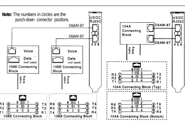
Procedure 2-7b: Connect
Without 885A Adapter
IVP6 (6-Port) Boards
Connect IVP6 (6-port) boards as follows:
1. Make sure that the building wire pairs were run together to a type 104A or 108B connecting block or equivalent. Refer to Figure 2-8.
2. Use the supplied D6AM-87 6-conductor modular cables between the IVP6 board and the connecting block.
3. The numbers in circles in Figure 2-8 are the punch-down connector positions.
Note: The numbers in circles are the punch-down connector positions.
D6AM-87
D6AM-87
Installing the Hardware
Connecting the IFP Board Fax Lines
Voice lines must be connected to the IFP boards,
— Each IFP2 board has two 6-position modular jacks. Each of these modular jacks is used to connect one voice line. The top jack is used for line pair O. The bottom jack is for line pair 1.
— Each IFP4 board has two 8-position modular jacks. Each of these modular jacks is used to connect two voice lines. The top jack is used for line pairs O and 1. The bottom jack is for line pairs 2 and 3.
Procedure 2-8: Connect IFP2 (2-Port) Boards
Each IFP2 board is supplied with two 2- or 4-conductor modular cables having modular plugs wired as RJ11C at both ends. Connect IFP2 (2-port) boards by following these steps:
1. Plug one end of one of the supplied modular cables into the line 1 modular jack on the IFP2 board.
2. Plug the other end of the modular cable into a RJ11C modular jack for line 1. 3. Repeat the above steps for the second line (line 2).
Procedure 2-9: Connect IFP4 (4-Port) Boards
Each IFP4 board is supplied with two special “Y” cables having an 8-position
modular plug on one end and having 6-position, 2-conductor modular plugs wired as RJ11C on the other two ends. Connect IFP4 (4-port) boards by following these steps:
1.
2.
3.
4.
Plug one 8-position modular plug into the matching modular jack on the top of the IFP4 board.
Plug the 6-position modular plugs into separate RJ11C modular jacks for each line. The two 6-position ends of the cable are labeled “A” for port 1 and “B” for port 2.
Plug the second 8-position modular plug into the matching modular jack on the bottom of the IFP4 board.
Plug the 6-position modular plugs into separate RJ11C modular jacks for each line. The two 6-position ends of the cable are labeled “A for port 3 and “B” for port 4.
Installing the Hardware
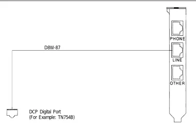
Connecting the DCP Board Digital Port Line
The DCP board must be connected to a digital port.
— The DCP board has three 8-position modular jacks. The middle jack (labeled LINE) is used to connect to the digital port.
— The DCP board is supplied with an 8-conductor (D8W-87) modular cable.
Procedure 2-10: Connect DCP Board
Connect the DCP board by following these steps:
1. Plug one end of the supplied D8W-87 modular cable into the middle modular jack on the DCP board (labeled LINE).
2. Plug the other end of the modular cable into the digital port modular jack assigned for use with the DCP board.
D8W-87
DCP Digital Port (For Example: TN754B)
Connecting Remote Maintenance
and CAS (SMDR) Ports
The Master Controller communicates with the System 75 or DEFINITY
Communications System and with the outside world through the system unit TTY ports.
— Serial Connector A (tty00) is used for remote access to the Master Controller. — Serial Connector B (tty01) is used for the Call Accounting System.
Master Controller DEFINITY/System 75
Figure 2-12. Remote Access and SMDR Port Connections
NOTE:
The circuit packs available in the telephone switch and the distance between the Master Controller and the telephone switch affect the method by which the CAS (SMDR) port connection is made.
■
■
■
Connections under 1000 feet can be made directly to the DCE port on the switch as detailed in Procedure 2-12A.
Connections under 2000 feet can be made to a type TN-726 data line port using an Asynchronous Data Unit (ADU) as detailed in Procedure 2-12B.
InstaIling the Hardware
Procedure 2-11: Connect Remote Maintenance Device
The location of connectors, switches, and indicators on the two RMD-HS models are shown in Figure 2-13 and Figure 2-14 and those on the two RMD models are shown in Figure 2-15. Connect the system unit to the remote access port by following these steps:
1.
2.
3.
4.
5.
6.
7. 8.
Connect one end of the RS-232 25-pin male-to-female cable supplied with the A/B Switch Kit to Serial Connector A (Serial Port 1 on MAP/5) of the Master Controller,
Connect the other end of the cable to the matching connector on the RMD or RMD–HS.
Connect one end of the modular cable supplied with the RMD or RMD-HS device to the modular jack marked LINE on the RMD or RMD-HS.
Connect the other end of the modular cable to the CO line or analog port for the remote access line.
If you have the RMD with switches on the bottom, set the switches as shown in Figure 2-15. The RMD Mk II and both types of RMD-HS do not have switches.
Connect the power supply to the round connector marked POWER on the RMD or RMD-HS.
Plug the power supply into an AC power outlet.
RMD-HS Mk IV
The Remote Maintenance Device-F models. It is installed in exactly the require any switches to be set.
S Mk IV (RMD-HS Mk IV) replaces all earlier same way as earlier models and does not
When you have connected the power supply to the RMD-HS Mk IV, turn the switch on the back of the RMD to the ON position. The indicators should appear as follows:
■ AA (Automatic Answer, on, green) ❑ RX (Received Data, off, red) ❑ TX (Transmitted Data, off, red) ❑ CD (Carrier Detect, off, red) ❑ OH (off Hook, off, green)
■ HS (High Speed, on, green) ■ TR (Terminal Ready, on, red) ■ MR (Modem Ready, on, red)
Installing the Hardware
RMD-HS
When the power supply is connected the RMD-HS will automatically come on. The indicators should appear as follows:
■ MR (Modem Ready, on) ■ TR (Terminal Ready, on) ❑ TX (Transmitted Data, off) ❑ RX (Received Data, off) ❑ OH (Off Hook, off) ❑ CD (Carrier Detect, off)
■ AA (Automatic Answer, on) ■ HS (High Speed, on) ❑ EC (Error Correction, off) ❑ DC (Data Compression, off)
The HS indicator is orange when lit. All other lamps are red when lit.
Remote Maintenance Device
HS
o
o
LINE –
RS-232
POWER
●
RMD
When you have connected the power supply to the RMD, turn the switch on the back of the RMD to the ON position. The indicators should appear as follows:
■ H S ■ A A ❑ C D ❑ O H ❑ R D ❑ T D ■ T R ■ M R
(High Speed, on) (Automatic Answer, on) (Carrier Detect, off) (Off Hook, off) (Received Data, off) (Transmitted Data, off) (Terminal Ready, on)
(Modem Ready, on)
All indicators are red when lit.
NOTE:
The CD and OH indicators are positioned slightly differently on the RMD Mk Il.
Bottom View Front View Back View
AC RS 232-C Telephone On/Off Power In Line Port Switch
Installing the Hardware
Connecting the CAS (SMDR) Port
There are three possible methods for connecting the CAS (SMDR) ports on the communications system and the Master Controller. Select the method to use based on the availability of the DCE port on the communications system, the distance between the Master Controller and the communications system, and the availability of circuit packs installed in the communications system.
■
■
■
System 75 XE, DEFINITY G1, G3i, G3s, and G3VS Communications Systems have DCE ports and can use any of the three connection methods based on other criteria. System 75 R1V3 and DEFINITY G3r Communications Systems do not have DCE ports and can only use circuit pack connections (Procedures 2-12B and 2-12 C).
The simplest, direct connection to the DCE port (Procedure 2-12A) has a limitation of 1000 feet (300 meters). If the distance between the Master Controller and the communications system exceeds 1000 feet, one of the other methods should be used.
Procedure 2-12A: Connect CAS (SMDR) Port
(DCE Port, Within 1000 Feet)
This method requires the DCE port. It can only be used with the System 75 XE or DEFINITY G1, G3i, G3s, and G3VS Communications Systems. It has a suggested maximum distance of 1000 feet (300 meters).
The following part is supplied with the Master Controller ❑ DB-9S to DB-25P Adapter
The following parts are supplied with DEFINITY IS Ill systems that include Call Accounting System:
❑ 355A Adapter ❑ 355AF Adapter
❑ 25-foot D8W-87 Modular Cord
Connect the Master Controller and the communications system SMDR port by following these steps:
1. Attach the 9-pin end of the 9-to-25-pin adapter to Serial Connector B (Serial Port 2 on the MAP/5) of the Master Controller.
2. Attach the 25-pin end of the 9-to-25-pin adapter to the 355AF adapter.
3. Connect one end of the D8W-87 modular cord to the 355AF adapter. 4. Connect the other end of the D8W-87 modular cable to the 355A adapter. 5. Attach the 355A adapter to the DCE port of the communications system.
Communications System
Connect to DCE Socket
Adapter Cable
Master Controller
Connect to Serial Port B or Serial Port 2
Installing the Hardware
Procedure 2-12B: Connect CAS (SMDR) Port
(TN-726 Circuit
Pack, Within 2000 Feet)
This method requires an available data line port on a TN-726 circuit pack. It is used primarily for System 75 R1V3 and DEFINITY G3r configurations. (These
configurations do not have DCE ports), It can also be used with the System 75 XE or DEFINITY G1, G3i, G3s, and G3VS Communications Systems when the DCE port is already in use for another purpose. Use this method when the distance is within 2000 feet (600 meters).
The following part is supplied with the Master Controller: ❑ DB-9S to DB-25P Adapter
The following part is supplied with DEFINITY IS Ill systems that include Call Accounting System:
❑ 25-foot D8W-87 Modular Cord The following additional parts are required:
❑ Z3A2 ADU ❑ M8AJ-87 Cable
NOTE:
ADUs must be used in pairs. In this case the TN726 Data Line Pack has built-in ADUs, so only one external ADU is necessary.
NOTE:
The combination of a Z3A2 ADU and a M8AJ-87 cable is equivalent to a Z3A4 ADU. You should order both pieces together by ordering the Z3A4.
NOTE:
Inside wire must be 4-pair, suitable for data; type 3 UTP data cable or better.
Connect the Master Controller and the communications system by following these steps:
1. Attach the 9-pin end of the 9-to-25-pin adapter to Serial Connector B (Serial Port 2 on the MAP/5) of the Master Controller.
2. Attach one end of the M8AJ-87 cable to the 25-pin end of the 9-to-25-pin adapter.
3. Attach the other end of the M8AJ-87 cable to the Z3A2 ADU.
5. Attach the other end of the D8W-87 modular cord to the data line port wall jack for the circuit leading to the TN-726 circuit pack.
Installing the Hardware
Procedure 2-12C: Connect CAS (SMDR) Port
(TN-754 Circuit Pack, Within 5000 Feet)
This method requires an available digital line port on a TN-754 circuit pack. It is used primarily for System 75 R1V3 and DEFINITY G3r configurations. (These
configurations do not have DCE ports). It can also be used with the System 75 XE or DEFINITY G1, G3i, G3s, and G3VS Communications Systems. Use this method when the distance is within 5000 feet (1500 meters).
The following part is supplied with the Master Controller: ❑ DB-9S to DB-25P Adapter
The following parts are supplied with DEFINITY IS Ill systems that include Call Accounting System:
❑ 25-foot D8W-87 Modular Cord ❑ 355A Adapter
❑ 355AF Adapter
The following additional parts are required: ❑ 7400A Data Module
❑ Power Supply
The following part is supplied with the 7400A Data Module: ❑ D8W-87 Modular Cord (25-foot)
Connect the Master Controller and the Communications System by following these steps: 1. 2. 3. 4. 5. 6. 7. 8. 9.
Attach the 9-pin end of the 9-to-25-pin adapter to Serial Connector B (Serial Port 2) of the Master Controller.
Attach the 25-pin end of the 9-to-25-pin adapter to a 355AF adapter. Attach one end of a D8W-87 modular cord to the 355AF adapter. Attach the other end of the D8W-87 cord to the 355A adapter. Attach the 355A adapter to a type 7400A Data Module.
Attach one end of a D8W-87 modular cord to the Data Module.
Attach the other end of the D8W-87 modular cord to the digital line port wall jack for the circuit leading to the TN-754 circuit pack.
Connect the power supply to the 7400A Data Module.
Master Controller
Connect to Serial Port B or Serial Port 2
Installing the Hardware
Starting the Master Controller
CAUTION:
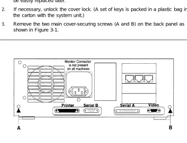
Before doing anything else, make sure that the voltage and the frequency of the wall power outlet are identical to those specified on the sticker affixed to the back panel of the system.
Procedure 2-13: Supply Power to the Master Controller
The standard power cord supplied with the system is detachable and plugs into the input power connector at the rear of the chassis. The input end terminates in a standard 3-prong plug for 115 VAC operation. Do not change the line voltage select switch that is set for 115 VAC.
DANGER:
You must use a 3-prong grounded outlet to eliminate the danger of shock.
1. Be sure the system unit power is OFF and that the voltage select switch located near the power connector on the rear of the system unit is preset for 115 VAC operation.
2. Connect the female end of the power cord to the connector at the rear of the system unit.
3. Connect the male end of the power cord to the surge protector/power strip. 4. Connect the surge protector/power strip power cord to an AC power source.
NOTE:
Procedure 2-14: Start the System
1. Remove the shipping insert from the tape drive by pushing it into the tape drive until it clicks and then releasing it.
2. Turn on the monitor.
3. Make sure that there is paper in the printer. Then turn on the printer. (Refer to the printer manual.)
4. Press the system-unit power switch to the ON position.
Installing the Hardware
Procedure 2-15: Observe the
Power On Self-Test (POST)
Each time the system is turned on or reset, POST runs automatically and checks the CPU, keyboard, video display, memory, and most built-in peripheral devices. The memory test takes 3 to 15 seconds to complete. During a soft boot (pressing the
[CTRL] – [ALT] – [DEL] keys at the same time), the system executes all POST tests except the memory test.
CAUTION:
Do not perform the [CTRL] – [ALT] – [DEL] soft boot unless you are prompted to do so.
When POST is completed, the system beeps once. A display similar to the following will appear.
xxxxxxxxxx BIOS Vx.xRx.x
008192 KB Memory Good
128 KB Shadow RAM Good (MC III only)
1 Diskette Drive(s) 1 Fixed Disk(s) 1 Parallel Port(s) 2 Serial Port(s)
Memory Cache On (MC III only) RAM BIOS Disable
Video ROM BIOS
Individual component tests are not reported unless the test fails. If the floppy disk, hard disk, or tape drive is not shown, refer to the following documentation:
■ Chapter 9, “Troubleshooting, ” in this document. ■ AT&T Master Controller Ill User’s Guide
■ AT&T Applications Controller User’s Guide (for the Master Controller II+) ■ AT&T MAP/5 User’s Guide
NOTE:
On an existing Master Controller II+, if the BIOS version displayed is lower than V1.1R2.5, you must return the Master Controller II+ and request a replacement.
On an existing Master Controller III, if the BIOS version displayed is lower than V1.2R1.2, you must return the Master Controller Ill and request a replacement.
Procedure 2-16: Log Into IS III
1. At the Login: prompt, type maint and then press [ENTER]
2. At the Password: prompt, type the password and then press [ENTER]
The Integrated Solution Ill Maintenance menu is displayed showing all the applications that are installed.
NOTE:
Only the applications installed are displayed. If AUDIX Voice Power and appear as one option. Either FAX Attendant are both installed, they will
may be present alone.
Integrated Solution III Maintenance
>AUDIX Voice Power/FAX Attendant (AVP/FA) Call Accounting System (CAS)
Technician Maintenance Exit
Move to an item using the arrow keys and press ENTER.
H E L P
Installing the Hardware
Testing and Adjusting the Installation
Procedure 2-17: Check Application Packages
1. After you have logged in and the Integrated Solution Ill Maintenance appears, select Technician Maintenance and press [ENTER].
menu
NOTE:
To select any item in a menu, you can use the arrow keys to move the cursor or type the first few characters of the menu item until the cursor moves to it. For any additional information on screen navigation, see “Screen Navigation” in the AT&T Integrated Solution III System Manager’s Guide.
The Technician Maintenance menu is displayed.
H E L P C A N C E L
Screen 2-2. Technician Maintenance Menu Technician Maintenance
Administer Integrated Solution III Backup Files
Full Screen UNIX >Maintenance Log
Password Protection Printer Setup Restore Files Set Time and Date System Shutdown
Voice System Administration
NOTE:
Application-specific selections such as Voice System
Administration only appear if the corresponding application(s) are installed.
2. Select Maintenance Log and press [ENTER],
The Maintenance Log menu is displayed.
I
I
Maintenance Log Disk Usage Report>Display Installed Applications Fax Board Diagnostics
IVP Board Diagnostics Printer Test
System Boot/Shutdown Log TTY Check
Move to an item using the arrow keys and press ENTER.
HELP CANCEL
Screen 2-3. Maintenance Log Menu
NOTE:
Application-specific selections such as Fax Board Diagnostics or
Installing the Hardware
3. Select Display Installed Applications.
If any of the essential software necessary to run Integrated Solution Ill, shown on Screen 2-4, or the ordered applications do not display on the screen, the software has not been installed properly.
The software list should also include all installed application packages. Refer to Chapter 4, “Adding and Removing IS III Applications” for more information on application software display.
NOTE:
It may be necessary to press [F3] (NEXTPAGE) to see all installed packages.
Display Installed Applications
Cartridge Tape Utilities - Version 2.1
DEFINITY Integrated Solution III Platform Software R1.x Editing Package Version 2.0
FACE HELP Version 1.2 FACE Version 1.2.1 FMLI Version 1.2
Remote Terminal Package V2.0
PREVPAGE NEXTPAGE C A N C E L
Screen 2-4. Display Installed Applications
NOTE:
The "x” following the applications listed on the menu represents the release number of the software. Your display will contain the actual release number of the applications installed on
Procedure 2-18: Test the CAS (SMDR) Port
To determine whether the CAS (SMDR) steps:
1. 2.
3.
4.
5. 6.
The switch must be administered
port is connected properly, follow these
to send SMDR.
From the Integrated Solution Ill Maintenance Menu, select Technician Maintenance and press lENTER].
The Technician Maintenance menu appears. Select Maintenance Log and press [ENTER].
The Maintenance Log menu appears. Select TTY Check and press [ENTER].
If a message appears that the port is not connected, verify that the switch has been administered to send SMDR. Then check the physical connections, cables, and connectors.
Press [F3] (CONT) to return to the Maintenance Log menu.
Press [F1] (CANCEL) twice to return to the Integrated Solution Maintenance menu.
Procedure 2-19: Test the Remote Access Port
To test the remote access port, call the AT&T Support Center and request the following services:
1. Request the Support Center to call the remote access port and log in to verify proper operation.
Installing the Hardware
Procedure 2-20: Initialize the Printer Setup
(If Applicable)
To initialize the printer setup, follow these steps: 1. Select Printer Setup
PRESS [ENTER].
The Parallel Printer Port
from the Technician Maintenance menu, and then
Setup window appears.
Parallel Printer Port Setup
Port Number: 01 (/dev/lp)
Device Currently On Port: Printer
Printer Type: AT&T570
Printer Name: islpr
Should filter be used: No
Press the CHOICES key to make a change. Press SAVE when you complete the form.
Screen 2-5. Parallel Port Setup
2. Press the [F2] (CHOICES) function key to display the list of available printers.
— The AT&T Applications Printer (wide carriage model) requires that the value be set to AT&T570.3
— The AT&T Call Accounting System Printer (narrow carriage model) requires that the value be set to AT&T571.4
— An HP LaserJet Series II or equivalent requires that the value be set to
3. Use the arrow keys to make your selection, then press [ENTER]. 4. Change the Should Filter be used: field to Yes.
NOTE:
No other fields can be changed.
5. Press [F3] (SAVE) to save the information you entered.
The screen displays your selection and asks for confirmation. 6. Press [F3] (CONT) if it is correct or [F6] (CANCEL) if not.
7. Press [F3] (CONT) to return to the Technician Maintenance window.
Procedure 2-21: Test the Optional Printer
This test submits a job to the printer so that you can verify the connections.
NOTE:
Do not perform this operation if you are not using a printer. Use [F6] (CANCEL) if you have selected this test by mistake.
To run the Printer Test, do the following from the Maintenance Log:
1. Select Printer Test from the Maintenance Log window and press [ENTER].
The Confirm Printer Test window is displayed.
The system informs you that the current printer configuration defaults are being written to the printer.
If the printer test fails, first check to see that the printer is powered, on-line, and has paper. Also check that any configuration jumpers or switches
described in the printer documentation are properly set. Next check the printer cable for proper connections. Should the fault persist, substitute the cable and printer with known good units to determine the faulty component.
2. Press [F3] (CONT) to get the job output.
Installing the Hardware
Procedure 2-22: Test the DCP Board and Port
There is no procedure specifically designed to test the general, if any call can be processed by AUDIX Voice
the DCP board and port are operating correctly. (There may still be other problems on some analog ports.) All calls are initially routed to the DCP port and then are transferred to an IVP port.
DCP board or port. In Power or by FAX Attendant,
The following scenarios can occur:
■ A call is made to the DCP channel and is answered: this generally indicates that the DCP channel is operating properly.
A call is made to the DCP channel and it rings but does not answer: this usually indicates a problem in switch administration.
A call is made to the DCP channel and the channel is busy: this generally indicates a problem with the DCP board.
A call is made to the DCP channel but fails to transfer to a voice for additional processing: this generally indicates a problem with an analog port (wiring or hardware), a class of restriction problem, or a problem with administration in the switch, AUDIX Voice Power, or FAX Attendant.
NOTE:
If AUDIX Voice Power or FAX Attendant have not yet been
administered, only the DCP port and board can be checked. Calls will not be transferred properly until after channel mapping has been completed and services have been assigned to channels.
As a troubleshooting procedure, follow these steps:
1. If the DCP channel is busy, unplug the D8W-87 cable from the LINE jack of the DCP board and connect it to a digital telephone set. Go to another telephone connected to the switch and make a call to the DCP extension. If the telephone connected to the DCP extension rings and can be answered, the switch and basic administration are okay, and the problem is most likely with the DCP board. If the telephone connected to the DCP extension does not ring, or cannot be answered, there is a problem with the administration of the DCP extension on the switch. If a problem with the DCP board is
suspected:
a. Verify all connections. The D8W-87 cable should be connected to the middle jack (labeled LINE) on the DCP board.