IoT Technology Based Underground Cable
Fault Distance Detection System Using
ATmega328P Microcontroller
Tanmay Kedia1, Abhijeet Lal2, Dr. Abhishek Verma3
UG Student, Department of EEE, BIT Durg, Chhattisgarh. India1
Assistant Professor, Department of EEE, BIT Durg, Chhattisgarh. India2
Associate Professor, Department of EEE, BIT Durg, Chhattisgarh. India3
ABSTRACT:The objective of this paper is to determine the location of fault in underground cable lines[1] from the source station to exact location of fault in any units, here in kilometres. Whenever a fault occurs in the underground cable line for some reason, the repairing process relating to that faulted cable becomes difficult owing to lack of proper system for tracking the exact fault location and the type of fault occurred in the cable. For this, a system has to be developed to find the exact location of the fault in the distribution line system for all the three phases R, Y & B for different type of situations of faults. Here in this paper single line to ground, double line to ground & three phase faults have been considered.Therefore, the basic concept of Ohm’s law[2]is found suitable in principle to develop a fault location tracking system. Based on the Ohm’s Law, it is found that the resistance of the cable is proportional to its length under constant conditions of temperature and the cross section area and therefore if a low DC voltage is applied at the feeder end through a series of resistor in cable lines, the current would vary depending upon the location of fault in the cable. Here a system is developed which consists of a microcontroller, LCD display, Fault Sensing Circuit Module, IoT Wi-Fi Module and proper power supply arrangement with regulated power output.Hence, if there is a short circuit in the form of line to ground[3] in any phase/phases, the voltage across series resistors changes accordingly and an analog signal in the form of voltage drop is generated by the fault sensing circuit of the introduced system, which is then fed to an ADC inbuilt in already programmed microcontroller to create the exact digital dataand after processing the data the output will be displayed in the connected LCD with the exact location of fault occurred in kilometres from the source station and simultaneously also indicate the corresponding R, Y, B phase where fault occurred with the exact distance. The same processed information output will appear in the webpage through connected IoT Wi-Fi Module.In this system, ATmega 328P micro controller [4] is used. Here the current sensing of circuits made with a combination of resistors is interfaced to ATmega328 micro controller with the help of internally inbuilt ADC for providing the digital data to microcontroller. The fault sensing circuit is made with the combination of set of series resistors &the set of switches alongside each resistor. The relays are controlled by the relay driver. A 16x2 LCD display is connected to the microcontroller to display the information of phase/phases and location of fault in kilometres.
KEYWORDS: Underground Cable System, Ohm’s Law, ATmega 328P micro controller, Fault Sensing Circuit, IoT Wi-Fi Module, LCD Display.
I. INTRODUCTION
Study of cable failures and development of accurate fault detection and location methods has been interesting research topics in the past and present. Fault tracking entails determination of the presence of a fault, while fault location detection includes the determination of the physical location of the fault. However, this fault detection and fault location detection technology for underground power distribution systems is still in developing stages.[6]
Before fixing any fault in cables, the fault has to be identified first. There are many ways to find the cable fault location. This paper deals with the method to locate faults and identify the phase line in damaged cables. A basic idea of fault location and phase identification in the pictorial view is undernoted.
Fig.1: Schematic Diagram of Basic Idea
II. LITERATURESURVEY
Frequent fault in underground cables due to the breakdown of paper plastic insulation [7]due to chemical reaction or poorworkmanship during installation and the difficulties in locating the approximate fault area have been a serious problem.Most Underground Faults are located by unearthing the entire length of cable to enable visual inspection to be carriedout. In case where visual inspection is not helpful then the entire length of cable is replaced. This manual method is notonly expensive but also results in heavy loss of revenue to the power distribution company. This research is aimed atdesigning an underground cable fault location distancedetection to solve this problem.The research work will help inidentification and location of underground cable fault without unearthing the entire length of the cable before repair orreplacing entire cable due to difficulty in locating the fault.
III.WORKINGPRINCIPLE&OPERATION
Principle
Operation
The operation of the system states that when the current flows through the fault sensing circuit module the current would vary depending upon the length of the cable from the place of fault that occurred if there is any short circuit fault with the Single Line to ground fault, or double line to ground fault, or three phase to ground fault.[8] The voltage drops across the series resistors changes accordingly and then the fault signal goes to internal ADC of the microcontroller to develop digital data. Then microcontroller will process the digital data and the output is being displayed in the LCD connected to the microcontroller in kilometres and phase as per the fault conditions. This Output is also displayed in the webpage through the IoT Wi-Fi Module ESP8266 connected to the system.
The power supply given to the system is 230V ac supply. This 230 V supply is fed to the two Adapter Modules (12 V, 2 Amps. each). The adaptor module 1 and 2 converts the AC voltage to DC. The ripple in output of adaptor module 1 is then removed with the help of a 1000 microfarad electrolytic capacitor. Since a constant 5 V voltage source is desired for our system, because the Microcontroller (ATmega328), 16x2 LCD (Liquid Crystal Display), Relay Drivers and Relays, Fault Sensing Circuit Module [9], IoT Wi-Fi Module[10], etc. and the other components work at 5V supply, hence we are using three voltage regulators (7805). These voltage regulators convert the filtered output to 5V constant supply voltage. The first voltage regulator (VR1) feeds the 5 Volts
supply to the microcontroller, LCD display, and the set of series resistors while the second voltage regulator VR2
feeds the relay driver IC ULN2003A and 3 three relays. The third Voltage regulator is connected to the IoT ESP8266 Wi-Fi Development Board Module which gives 5 Volts DC supply to it.
The project consists of three relays which are driven by a relay driver IC ULN2003A. The relays used here switches off/on the bulb loads R, Y and B to indicate the fault being occurred in corresponding phases.
IV.DEVELOPMENTOFCIRCUITDIAGRAM
A. Simulation of Fault Sensing Circuit Diagram in Proteus 8 Software
A system of set of series resistors in each phase resembling 3 phase underground cable lines along with slider switches
for fault creation has been developed as shown in Fig. 2.
The Table 1 shows the observation of resistances and currents while simulating the ault sensing circuit.
Table 1: Observation Sheet for Fault Sensing Circuit
Location of Fault Cable Resistance During Fault Conditions, RDC(in
kΩ)
Total Resistance of Cable During Fault Condition, RT (in
kΩ)
Current flowing through Fault Sensing Circuit, IF
(in µA)
At 1 Km 10 20 250
At 2 kms 20 30 167
At 3 kms 30 40 125
At 4 kms 40 50 100
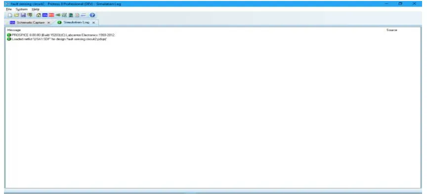
Fig.3 shows the simulation log report of fault sensing circuit developed in Proteus 8 Software.
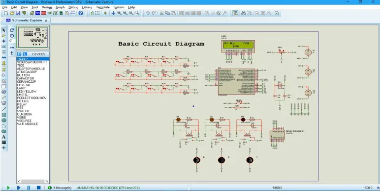
B. Simulation of Basic Circuit Diagram in Proteus 8 Software
A fault detecting system is developed in Proteus 8 using microcontroller ATmega328P IC, LCD display, Relays, fault
sensing circuit, etc. as shown in Fig.4.
Fig.4: Simulation of Basic Circuit Diagram (with fault) in Proteus 8 Software
The Table 2 shows the observation of voltage drops and calculated digital ADC data for each kilometre and
upto four kilometres with pre-fault voltage source of 5 Volts. while simulating the Basic circuit diagram.
Table 2: Observation Sheet for Basic Circuit Diagram
Location of Fault
Pre-fault Voltage, VRef
(in Volts)
Calculated Voltage Drop during Fault Conditions, Vd (in Volts):
Vd = VRef - {IF x (RT - RDC}
Calculated Digital ADC Data for Microcontroller :
(Vd x 1024)/VRef
At 1 Km 5 2.50 512
At 2 kms 5 3.33 682
At 3 kms 5 3.75 768
At 4 kms 5 4.00 819
Fig.5 shows the simulation log report of basic circuit diagram of fault detection system developed in Proteus 8
Fig.5: Simulation Log Report of Basic Circuit Diagram in Proteus 8 Software
C. Circuit Diagram with IoT Wi-Fi Module
A fault detecting system is developed using above statedbasic circuit diagram in Fig. 4 with the help of IoT Wi-Fi
Module as shown in Fig.6.
V. MAJORCOMPONENTSUSED
1. AC/DC ADAPTER
An AC/DC adapter[11] or AC/DC converteris a type of external power supply, often enclosed in a case similar to an AC plug. Other common names include plug pack, plug-in adapter, adapter block, domestic mains adapter, line power adapter, wall wart, power brick, and power adapter. This module is 230 V AC – 12V, 2A DC Adapter Module.
Fig.7: 230 V AC- 12 V, 2 A DC Adapter
2. IoT Wi-Fi ESP8266 Module
The Internet of things (IoT) is the network of physical devices, vehicles, home appliances and other items embedded with electronics, software, sensors, actuators, & connectivity which enable these objects to connect and exchange data. The IoT allows objects to be sensed or controlled remotely across existing network infrastructure, creating opportunities for more direct integration of the physical world into computer-based systems, and resulting in improved efficiency, accuracy and economic benefit in addition to reduced human intervention.Lolin NodeMCU V3 is an open-source firmware and development kit that helps you to prototype your IOT product. The V3 is a “version” invented by producer LoLin to signify minor improvements to the AMICA V2 boards.
3. Microcontroller
The ATmega328/P is a low-power CMOS 8-bit microcontroller based on the AVR® enhanced RISC architecture. This empowers system designer to optimize the device for power consumption versus processing speed. It has 32KBytes of In-System Self-Programmable Flash program Memory, 1KBytes EEPROM, 2KBytes Internal SRAM and Write/Erase Cycles of 10,000 Flash/100,000 capable EEPROM. It can be programmed using Arduino IDE.
Fig.9: ATmega328P Microcontroller IC
4. Fault Sensing CircuitModule
VI.FLOWCHART
Fig.11: Programming Flowchart
VII. EXPERIMENTALRESULTS
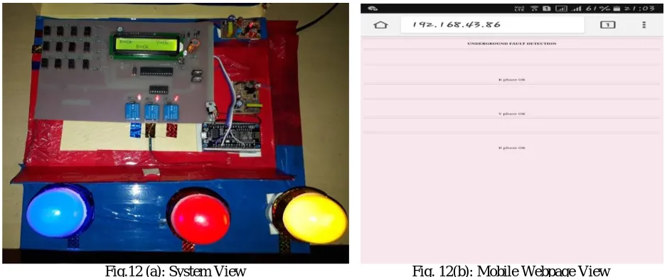
Case 1:When No fault has occurred. Outcome is R, Y and B all “OK”.
Fig.12 (a): System View Fig. 12(b): Mobile Webpage View
Case 2:Fault occurred when SW2 of phase Y and phase B are closed. Outcome is Fault has occurred in phase Y
and phase B at 2 Km.
Fig.12 (c): System View Fig. 12 (d): Mobile Webpage View
Likewise there might be various cases of fault occurred in all these three cable line i.e. fault may occur in single phase, in two phases and also three phases at a time.
VIII. CONCLUSION
that can effectively satisfy the requirement of exact fault location detection in the underground cable system and it is believed that this model can be a promising technology to solve future fault location detection problem.
REFERENCES
[1]. Clegg, Underground Cable Fault Location. New York: McGraw- Hill, 1993
[2]. Manish Paul, Raj Kamal Kakoti, 'Underground Cable Fault Locator', IARJSET, Vol.3, Issue 9, September 2016.
[3]. M.S. Choi, D.-S. Lee, and X. Yang, "A line to ground fault location algorithm for underground cable system," KIEE Trans. Power Engg., pp. 267-273, Jun. 2005.
[4].Atmel-8271-8-bit-AVR-Microcontroller-ATmega48A-48PA-88A-88PA-168A-168PA-328-328P_datasheet_Complete, Microchip.
[5]. Nikhil Kumar Sain, Rajesh Kajla, Mr.Vikas Kumar, “Underground Cable Fault Distance Conveyed Over GSM”, IOSR-JEEE, Volume 11, Issue 2 Ver. III (Mar. – Apr. 2016).
[6]. C. Bascom, "Computerized Underground Cable Fault Location Expertise", Transmission and Distribution Conference, 1994, Proceedings of the 1994 IEEE Power Engineering Society.
[7]. Tarlochan, Sidhu, S. Xu, Zhihan, "Detection of Incipient Faults in Distribution Underground Cables", IEEE Transactions on Power Delivery, Vol. 25, No.-3, July 2010.
[8]. Darvhankar G.S, Gharpande A.S, Bhope S.D, Meshram A.S, Bobad A., “Study of 3-phase Underground Cable Fault Locator Using Acoustic Method”, I.J.A.E.R.D., Vol. 2, Issue 1, Jan. 2015.
[9]. Tanmay Kedia, Vinita Sahare, Kanchan Kumar Bauri,Rajendra Kumar Sahu, Sanjeev Kumar, Abhijeet Lal, "Underground Cable Fault Distance Detector using ATMega328 Microcontroller", IJAREEIE, Vol.6, Issue 10, October 2017.
[10]. Mr. N. Sampathraja, Dr. L. Ashok Kumar, Ms. V. Kirubalakshmi and Ms. C. Muthumaniyarasi, Mr. K. Vishnu Murthy, “IoT Based Underground Cable Fault Detector”, IJMET, Volume 8, Issue 8, August 2017.
[11].Byoung-Hee Lee, Ki-Bum Park, Chong-Eun Kim, “No-Load Power Reduction Technique for AC/DC Adapters”, IEEE Transactions on