Division 5
INVESTIGATION OF INTERFACE NON-LINEARITY ON
SOIL-STRUCTURE INTERACTION ANALYSES
Dhrubajyoti Datta1, Amit H. Varma2, Jungil Seo3and Justin Coleman3
1 PhD Candidate, Lyles School of Civil Engineering, Purdue University, USA
2 Professor, Lyles School of Civil Engineering, Purdue University, USA
3 Postdoctoral Research Associate, Purdue University, USA
4 Seismic Research Group Lead, Idaho National Lab, USA
ABSTRACT
Soil structure interaction (SSI) plays a crucial role in the behavior, analysis and design of large structures of high importance such as power plants, processing facilities, hospitals, precision engineering facilities, hydraulic power infrastructure, etc. SSI can have significant influence on the calculated in-structure response spectra (ISRS), and the calculated seismic design demand forces for structures subjected to earthquake loading combinations. Our hypothesis is that nonlinearities in the soil-structure interface have the potential to further reduce the peak acceleration demands due to energy dissipation. The sources of these nonlinearities include: (i) nonlinear soil behavior, (ii) nonlinear structure behavior, and (iii) nonlinearities such as gapping and sliding across the soil-structure interface. The goal of this exploratory study is to compare numerical non-linear soil-structure interaction (NLSSI) analyses results with measured ground motions in order to evaluate sources of geometric nonlinearity contributing to the observed reduction in peak acceleration between the ground and the in-structure response. To achieve this goal, a series of linear (SSI) and nonlinear (NLSSI) analyses were performed using ground motion data and site soil profile measured near the Fukushima Daichii nuclear power plant Unit 6. The focus of the analyses is on evaluation of two specific nonlinear effects from localized soil nonlinearity; gapping and sliding. A full scale finite element model of the NPP-soil assembly is simulated in ABAQUS and benchmarked with linear soil structure interaction (LSSI) models in LS-DYNA [1]. The geometric non-linearities are then introduced to the linear SSI model and the acceleration response is tracked through comparison of response spectra. In order to assess the physical nature of the structural response, parametric studies are performed on the basis of friction (sliding effects) and penalty contact (gapping effects) formulations at the interface.
THE FUKUSHIMA DAICHII NUCLEAR POWER PLANT
The Fukushima Daichii Unit 6 is considered in this study. It is a boiling water reactor (BWR Mark II) located in the Futaba District of Fukushima Prefecture, Japan. A schematic cross-section view of a typical BWR Mark II containment is shown in Figure 1. A numerical model uses the dimensions of the Fukushima NPP Unit 6 (including the reactor and turbine buildings) with an idealized reactor assembly resting on a non-linear soil domain surrounding the structure and an infinitely large linear soil domain.
Fig 1. Schematic cross-section view of BWR Mark II containment (Coleman, 2015).
Fig 2. Fukushima Daiichi nuclear power plant schematic locations of boreholes on site and interpreted soil layering near Unit 6 [3]
Table 1. Maximum Accelerations recorded in three directions for borehole location near Unit 6 [3]
Location Depth
(m)
Obs. Pt.
Max Acceleration (Gal) Shear Velocity
(m/s)
Compressional Wave (m/s)
NS EW UD
Borehole near Unit 6
-31.5 P13 252 405 194 470 1710
-31.5 P4 209 387 189 470 1710
-143.5 P14 313 302 113 580 1820
Table 2. Elastic soil properties for observation point near Unit 6 [3]
Location Obs. Pt. Density
(kg/m3) PR
Young’s
Mod (Pa) Shear Mod (MPa)
Borehole near Unit 6
P13 252 0.46 1285090459 440.36
P4 209 0.46 1285090459 440.36
NUMERICAL MODELING AND ANALYSIS
The methods employed to perform soil structure interaction analysis under dynamic loading can be broadly classified into two main categories; the direct method and the substructuring method. The direct method allows us to simulate the response of the soil-structure system in a single step, utilizing the finite element approach. The system is comprised of a finite soil domain with well-defined boundaries where the interactions between the basemat and soil can be accounted for in a single finite element framework by analyzing the material and geometrical nonlinearities between them. The substructuring method on the other hand treats the soil and structure as separate components and the responses are superposed to obtain the overall response of the structural system. This method allows for the analysis of the free field soil response and the structural response through independent computational schemes. However, it does not consider the nonlinearities and interaction properties associated with the interface between the soil and the basemat. The dynamic stiffness of the soil domain is represented in a condensed form at the soil-structure interface. The substructure method is primarily applicable for linear SSI analysis, though newer software tools such as DEEPSOIL use non-linear backbone curves for material definition coupled with structural and Rayleigh damping. The response of the soil domain is computed through a site response analysis scheme where the ground motion is provided as input at the bedrock or at a certain level in the confined soil domain. The output from the site response analysis acts as the input for the assessment of the structural response. The direct method of analysis has been used to perform the NLSSI analysis in this paper.
The change in frequency content of the ground motion when seismic waves propagate through the soil, primarily occurs due to variations in material properties of the soil domain, and other site specific parameters. SSI plays a significant role in assessing the in-structure response of the NPP structure when the amplified waves reach the soil-basemat interface. This in-structure response spectra can be used to assess the seismic margins of the forces and moments, which are essential to the design of individual structural elements. Previous exploratory studies have shown that the nonlinearity associated with SSI reduces the peak acceleration demands of the structure due to energy dissipation.
Finite element model of the NPP for simulation of SSI effects
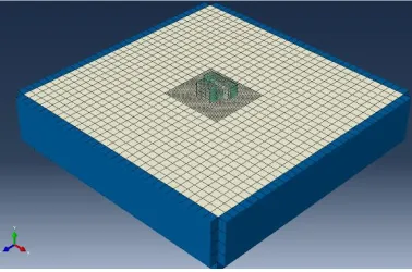
The primary motivation of the study is to compare numerical NLSSI results with the ground motion and site profile data obtained from field, and benchmark it with pre-existing linear finite element (LSSI) models which were simulated using LS-DYNA [1]. A detailed model of the NPP assembly is built with a layer of fine meshed soil surrounding the reactor and turbine building basemat which is tied to a large soil strata. The loading is applied to the structure in terms of an acceleration input at the base of the soil strata. The linear in-structure acceleration response is computed to study acceleration attenuation effects and is benchmarked with LS-DYNA models. The LSSI analysis is performed with elastic material properties (elastic modulus, Poisson’s ratio, and mass density) and material nonlinearities are ignored. The soil domain, superstructure, mesh properties, loading conditions and boundaries are consistent throughout the analysis process. The mesh size of the structure and the soil domain surrounding the basemat is kept the same to facilitate wave propagation at the interface, avoiding mesh deformation effects.
The model is primarily split into three parts, viz. (i) Concrete superstructure and substructure which is linear elastic (Elastic modulus (E):30 X 10^9 N/m2 ; Poisson’s ratio (ν): 0.25; Density: 2400 kg/m3) comprising of solid, homogeneous sections and built of C3D8R reduced integration block elements. The structure is simplified by neglecting internal equipment. Additional concrete finite elements are included in the structure to take the mass of the reactor unit into account. Partial structured meshing with sweep control is used to mesh the complex regions of the reactor assembly using tetrahedral C3D10M elements; (ii) Reinforcement cage: linear elastic with a circular profile (Elastic modulus (E):200 X 10^9 N/m2;
Poisson’s ratio (ν): 0.3; Density: 7750 kg/m3) comprised of B31 beam elements. The steel reinforcement
soil: linear elastic (Elastic modulus (E):0.15 X 10^9 N/m2; Poisson’s ratio (ν): 0.3; Density: 2500 kg/m3) composed of C3D8R elements. The soil strata surrounding the basemat has a finer mesh (same as the structure) as compared to the rest of the soil domain to maintain continuity of the interactions at the interface.
Fig 3: FE Model parts of Fukushima NPP, Unit 6
The soil domain is modelled to be six times the size of the structure in plan and is of uniform dimension in all directions, such that an infinite domain can be simulated. When the domain size is increased, computation becomes more complex and time-consuming. The ABAQUS model shows that waves are reflected from the boundaries in spite of a large soil domain. Hence, the boundary conditions are modified to address this issue and has been described in the next section.
Soil Domain and Boundary Condition
A number of boundary conditions are applied in conjunction with several constraint parameters, to study the reflection of waves and minimize the interference of external waves in computation of the acceleration response. Previous studies show that certain boundary conditions such as the *BOUNDARY_NON_REFLECTING in LS-DYNA are effective in simulating non transmitting boundaries. Due to absence of similar boundary conditions in ABAQUS, a brief study was conducted to calibrate the ABAQUS model. A set of models with similar material properties as previous FE models [1] and dissimilar boundary parameters are considered for calibration:
(i) Model 1: boundaries constrained to move with internal reference nodes and individual
boundary elements are constrained to move in pure shear. Infinite elements surround the external face of the soil domain in all directions to simulate non-reflecting boundaries.
(ii) Model 2: infinite domain in all sides with the bottom face constrained to move with internal
nodes. The acceleration is applied at the base
(iii) Model 3: no constraints were defined for this model, with infinite domain in all directions.
(iv) Model 4: node region constrained at edges with infinite domain along all directions.
After performing simulations on a linear SSI model with the above mentioned boundary conditions, Model 1 is observed to behave in a similar fashion as previous LS-DYNA models [1]. It should be noted that only the translational degrees of freedom at the boundaries are constrained for the model while the rotational degrees of freedom are released. The individual surfaces have a node to surface coupling with the influence region extending to outermost points of the domain.
Fig 4: Model with infinite elements (highlighted in blue) surrounding the boundaries
When the model is surrounded by infinite boundary elements, without constraints, large amplifications are observed, which do not agree with the expected results. In case of model 4; where the entire node region in individual layers are constrained to move with the boundaries, the observed acceleration amplifications in the soil are much lower than expected. This is primarily due to the fact that the individual layers behave as rigid plates.
Since input ground motions are predominantly waves propagating in the vertical direction, it is applied at the base of the soil. However, in this case a within motion is available [2]; which is the acceleration data obtained from site, when the bottom soil domain or rock is assumed to be rigid. The simulation is performed in two steps. In the first step, static gravity loading is applied for a brief instant and propagated to the next step where the acceleration is scaled with respect to its amplitude and applied above the infinite element layer in terms of an acceleration-time history obtained from site. The linear or modal response of the system is performed using a pseudo-static analysis and the natural time period is found to be acceptable.
In case of outcrop motions, the load input has to be assumed as a force-time history dependent on the shear wave velocity, surface area and velocity-time history; with absorbing boundary conditions. Outcrop motions have not yet been analyzed to completion in ABAQUS, and is an ongoing study.
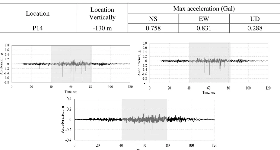
Table 3. Summary of ground motion input.
Location Location
Vertically
Max acceleration (Gal)
NS EW UD
P14 -130 m 0.758 0.831 0.288
Fig 6. Ground motion data used in simulations in: (a) EW , (b) NS, and (c) UD directions
LINEAR SOIL STRUCTURE INTERACTION (LSSI) ANALYSIS
The linear soil structure interaction analysis is performed without any material or geometric nonlinearities and then compared with the LSSI results from LS-DYNA [1]. The soil domain, superstructure, mesh properties, loading conditions and boundaries are consistent throughout the analysis process. In case of linear analysis, only elastic material properties are used for the simulations. The mesh size of the structure and the soil domain surrounding the basemat are consistent to facilitate wave propagation at the interface, avoiding mesh deformation effects.
The acceleration-time response history is obtained at the basemat of the reactor in contact with the soil as well as the sixth floor of the reactor building, to give us a clear idea of the attenuation effects, as waves travel through the interface into the superstructure. The free field motion used for the simulations captures the acceleration response every 0.01 sec. Hence, the field history output for the in-structure response acceleration is collected at the same frequency. A direct comparison of acceleration time history responses may not reflect the true behavior of the trends in results. For example, we cannot pinpoint a certain data point to be the maximum acceleration; due to different time integration schemes and hourglassing effects. A response spectrum analysis has been performed in order to compare the frequency content and peak pseudo spectral accelerations at the basemat and the top floor of the reactor building. This allows us to compare the trends in the attenuation of the in-structure response with existing models.
Comparative analysis and benchmarking of ABAQUS results with LS-DYNA
integration schemes, or adaptive meshing properties. However, this can be considered as a good benchmark for the NLSSI models which simulate the effects of geometric non-linearities at the interface.
Table 4. Summary of LSSI results
Maximum acceleration (g)
Locations EW
%age change
wrt F.F. NS
%age change
w.r.t F.F. UD
%age change w.r.t F.F.
Free field 0.580 0.457 0.370
RB-Basemat soil
(LS-DYNA) 0.518
-10%
0.359 -21.4% 0.385 +4%
RB-Basemat soil (ABAQUS) 0.520 -10.3% 0.391 -14.4% 0.367 -0.8%
RB-6th floor (ABAQUS) 0.429 -26% 0.387 -15.3% 0.329 -11%
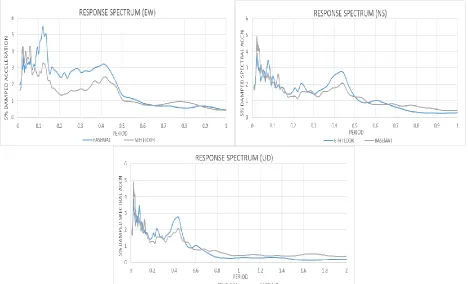
The time history responses are converted to response spectra using the Fast Fourier Transform algorithm. Similar trends in acceleration attenuation are observed from the acceleration-time response history as shown in Fig 7.
As observed in the response spectrum analysis, the peak accelerations occur at lower periods or high frequencies, owing to high stiffness of the soil. The basemat experiences higher pseudo spectral accelerations as compared to the 6th floor due to in-structure attenuation effects. The energy dissipation at the interface is a function of the mass of the structure, intensity or amplitude of the ground motion content, and modulus mismatch of the soil-structure boundary. This dissipation in energy is believed to be responsible for reduction of the acceleration.
NON-LINEAR SOIL STRUCTURE INTERACTION (NLSSI)
Geometric nonlinearities (gapping and sliding) across the soil-structure interface are considered in the nonlinear soil-structure interaction (NLSSI) analysis. To evaluate the influence of each source, a series of NLSSI analyses are performed. The results from LSSI case is used to evaluate the influence of nonlinear interface around the structure on the reduction of the maximum acceleration. A series of NLSSI models considering material and geometric nonlinearities were performed in LS-DYNA to simulate geometric nonlinearities across the interface [1]. A thin layer of elements using the *MAT_BRITTLE_DAMAGE material model were used to simulate gapping effects. The *automatic surface_to_surface tie-break contact was also used to simulate gapping and sliding effects resulting in high amplification of the acceleration-time output of the response and this could not be explained. In this article, the authors use a simple Coulomb friction model and a penalty contact formulation to study the effects of gapping and sliding across the interface. The unnatural amplifications observed in the LS-DYNA models are overcome using these contact formulations.
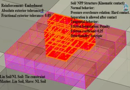
Fig 8. Nonlinear interaction and contact formulation in ABAQUS
ABAQUS-NLSSI MODEL TO SIMULATE GAPPING EFFECTS
The structure resting on soil exhibits inertial and kinematic interaction effects when subjected to ground motion. When the wave propagates from one medium to another, kinematic effects are observed due to change in elasticity and density of the media, resulting in reflection and refraction of incoming waves and a change in the wave propagation velocity. These kinematic effects primarily represent the change in response of the structure under the influence of free field motion. A simple kinematic contact definition is used for the soil-structure interface. To simulate gapping behavior, hard contact pressure overclosure relationship is implemented as the normal behavior; which allows separation after contact. The zero-penetration condition is enforced when the surfaces separate and the contact pressure reduces to zero. The meshing is performed in a way such that the nodes shared by the two adjacent parts move together.
The response spectrum at the free field, the bottom of reactor building basemat (RB-BM), and the bottom of turbine building basemat (TB-BM) are compared in Fig 8. From the response spectrum, it is observed that there is a reduction of the maximum pseudo spectral acceleration values at the reactor building basemat (RB-BM) and turbine building basemat (TB-BM).
ABAQUS-NLSSI MODEL TO SIMULATE SLIDING EFFECTS
Shear forces are also transmitted across the interface during contact apart from normal forces. The tangential or shearing behavior of the FE model is governed by a penalty friction formulation, based on the classical isotropic friction model in ABAQUS/Explicit. The basic idea is to relate the maximum allowable shear stress across the interface to the normal contact pressureusing a Coulomb friction model. The two contacting surfaces carry shear stresses up to a certain magnitude before they start sliding with respect to each other. Thisis determined by the critical shear stress which is further dependent on the coefficient of friction between the surfaces in contact. The coefficient of friction (µ) is varied to study its impact on the sliding behavior.
For a three dimensional model, there exists two orthogonal components of the critical shear stress along the interface. For simplicity, the friction coefficient is kept the same in both directions. The lateral loading is mainly controlled by the free field ground motion in addition to the normal contact stresses due to self-weight of the structure. The contact pressure for a node-based slave surface equals the normal pressure divided by the total cross sectional area of the contact node. However for ABAQUS/Explicit, the cross sectional area is always 1.0. Fig.9 shows the acceleration response behavior at the basemat due to variation in the friction coefficient.
Fig 10: Acceleration response spectrum for friction coefficients of 0.25, 0.35 and 0.15 at the basemat
(spectral accn in m/s^2 and time period in sec)
The peak spectral acceleration at the basemat is reduced as compared to the free field response spectra.It is observed that the peak spectral acceleration is higher at lower periods for higher friction coefficients. As the period increases, the peak spectral acceleration increases for lower friction coefficient. This is consistent with the fact that when the friction coefficient is higher, the interface is relatively stiff at higher frequencies. Hence, the acceleration response is higher. However, the probability of slippage increases at low friction coefficients. Hence, the energy dissipation across the interface occurs over a greater time period, thereby reducing the peak spectral acceleration response.
Comparison of gapping and sliding effects in ABAQUS
sensitivity study is performed to compare the gapping and sliding formulation with the case when the structure is tied to the soil, when gapping and sliding is arrested. Separation is permitted after contact for all simulations.
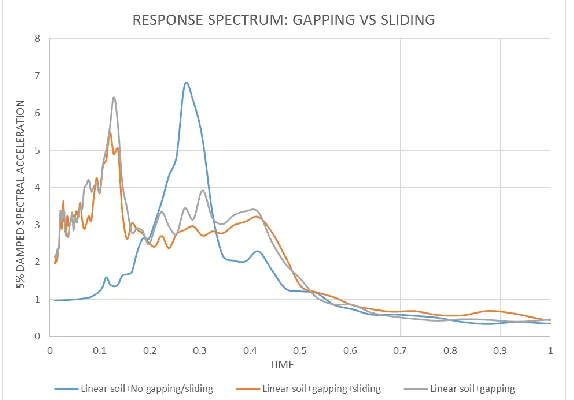
Figure 11: Response spectra for gapping and sliding vs. tied case
Upon performing the response spectrum analysis, we observe that the structure experiences higher spectral acceleration at lower frequencies when the basemat is tied to the soil suggesting a steady growth in the in-structure response. When gapping effects are introduced, the peak accelerations are found to occur at high frequencies owing to the loss of contact between the structure and basemat for certain ground motions with high frequency content. The pseudo spectral acceleration (PSA) is reduced when gapping effects are introduced as compared to the tied case. When the friction (sliding) component is introduced in addition to gapping, there is further attenuation of the acceleration response. The nonlinear interface helps in reducing the peak spectral acceleration by a small amount due to its softening characteristics. The highest PSA is observed for the no-gapping (tied) case, as the basemat experiences greater inertia effects and behaves as a single unit with the soil.
CONCLUSION
A series of linear and nonlinear soil-structure interaction analyses have been performed to explore the influence of interfacial nonlinearities on the seismic response (ISRS) of nuclear power plant structures. The study was motivated by the hypothesis that these nonlinearities could potentially reduce the maximum accelerations in the structural basemat relative to the values measured in the free field. Only geometric nonlinearities were explored in this study: (i) gapping, and (ii) sliding between soil and structure. Linear soil-structure interaction (LSSI) analysis was first performed in the time domain with elastic soil material properties followed by nonlinear soil-structure interaction (NLSSI) with Coulomb friction and penalty contact formulation in ABAQUS.
study.
References
[1] Varma, A. H., Seo, J. and Coleman, J. (2015). "Application of Nonlinear Seismic Soil-Structure Interaction Analysis for Identification of Seismic Margins at Nuclear Power Plants". INL/EXT-15-37382, Idaho National Laboratory, Idaho Falls, Idaho.
[2] Coleman, J. C., Bolisetti, C., and Whittaker, A. S. (2016). "Time-Domain Nonlinear Soil-Structure Interaction Analysis for Nuclear Facilities.", Nuclear Engineering and Design, 298, 264–278.
[3] Coleman, J. (2015), “Light Water Reactor Sustainability Program Seismic Data Gathering and Validation,” INL/EXT-15-34425, Idaho National Laboratory, Idaho Falls, Idaho.
![Table 2. Elastic soil properties for observation point near Unit 6 [3]](https://thumb-us.123doks.com/thumbv2/123dok_us/1532160.1187862/2.612.126.498.80.243/table-elastic-soil-properties-observation-point-near-unit.webp)