University of Windsor University of Windsor
Scholarship at UWindsor
Scholarship at UWindsor
Electronic Theses and Dissertations Theses, Dissertations, and Major Papers
1-1-2006
Engine management system for dynamometer testing.
Engine management system for dynamometer testing.
Andrew Leonard Zuccato
University of Windsor
Follow this and additional works at: https://scholar.uwindsor.ca/etd
Recommended Citation Recommended Citation
Zuccato, Andrew Leonard, "Engine management system for dynamometer testing." (2006). Electronic Theses and Dissertations. 7180.
https://scholar.uwindsor.ca/etd/7180
ENGINE MANAGEMENT SYSTEM FOR DYNAMOMETER TESTING
by
Andrew Leonard Zuccato
A Thesis
Submitted to the Faculty of Graduate Studies and Research through Mechanical, Automotive and Materials Engineering
in Partial Fulfillment of the Requirements for the Degree of Master of Applied Science at the
University of W indsor
Windsor, Ontario, Canada 2006
■ H Library and Archives H w H Canada
Bibliothgque et Archives Canada
Published Heritage Direction du
Branch Patrimoine de P6dition
395 Wellington Street 395, rue Wellington Ottawa ON K1A 0N4 Ottawa ON K1A 0N4
Canada Canada
Your file Votre reference
ISBN: 978-0-494-82886-1
Our file Notre reference
ISBN: 978-0-494-82886-1
NOTICE: AVIS:
The author has granted a non
exclusive license allowing Library and Archives Canada to reproduce, publish, archive, preserve, conserve, communicate to the public by
telecommunication or on the Internet, loan, distribute and sell theses worldwide, for commercial or non commercial purposes, in microform, paper, electronic and/or any other formats.
L’auteur a accorde une licence non exclusive permettant a la Bibliotheque et Archives Canada de reproduire, publier, archiver, sauvegarder, conserver, transmettre au public par telecommunication ou par I’lnternet, preter, distribuer et vendre des theses partout dans le monde, a des fins commerciales ou autres, sur support microforme, papier, electronique et/ou autres formats.
The author retains copyright ownership and moral rights in this thesis. Neither the thesis nor substantial extracts from it may be printed or otherwise reproduced without the author’s permission.
L’auteur conserve la propriete du droit d’auteur et des droits moraux qui protege cette these. Ni la these ni des extraits substantiels de celle-ci ne doivent etre imprimes ou autrement
reproduits sans son autorisation.
In compliance with the Canadian Privacy Act some supporting forms may have been removed from this thesis.
Conformement a la loi canadienne sur la protection de la vie privee, quelques formulaires secondaires ont ete enleves de cette these.
While these forms may be included in the document page count, their removal does not represent any loss of content from the thesis.
Bien que ces formulaires aient inclus dans la pagination, il n’y aura aucun contenu manquant.
1*1
ABSTRACT
Production passenger vehicles employ engine control strategies with a number of
adaptive functions to improve drivability, as well as diagnostic and protection
functions to prevent engine damage. While these features are desirable to the
customer, they introduce challenges for dynamometer testing. Adaptive and
protective controls can significantly alter fundamental operating parameters,
thereby generating variability in engine performance. It would be beneficial to
implement a simplified control system for dynamometer testing that delivers
consistent performance at all times.
An EFI Technology Euro 12 controller was adapted to run a Ford V8 gasoline
engine. A basic pedal-follower throttle strategy was used and calibrations were
developed to duplicate production engine performance. Closed-loop wide-band
air-fuel ratio control enhanced fuelling repeatability. A Global Electronics
Universal Solenoid Driver enabled independent control of the automatic
transmission. Engine output repeatability was compared to the production
ACKNOWLEDGEMENTS
I would like to thank my advisors, Dr. Jimi Tjong and Dr. Ming Zheng, as well as
my thesis committee and the Ford Powertrain Research & Development Group
fo r their support in completing this work. I would also like to give special
recognition to the following individuals:
Ole Buhl
Russell Ellwood
Tony Fountaine
Fabrice Flumblet
Jan Linsel
Barry Marzin
Ted Murawski
Darin Truman
TABLE OF CONTENTS
ABSTR AC T... ... ... ... iii
ACKNO W LEDG EM ENTS...iv
LIST OF TABLES... viii
LIST OF FIG U R E S ...ix
LIST OF EQ U ATIO N S... xi
NOM ENCLATURE...xii
CHAPTER 1 INTRODUCTION...1
1.1 Introduction... 1
1.2 Engine S pecifications... 2
1.3 Transmission S pecifications... 3
1.4 Electronic Engine Control S yste m s... 3
1.5 Research O b je ctive s... 3
1.6 Thesis O u tlin e ... 4
2 REVIEW OF LITERATURE... 5
2.1 Engine A ctu a to rs... 5
2.1.1 Coil-On-Plug Assembly (C O P )... 5
2.1.2 Fuel In je cto r... ....6
2.1.3 Electronic Throttle/Throttle-By-W ire... 8
2.1.4 Variable Camshaft Timing System (V C T )... 9
2.1.5 Charge Motion Control Valves (C M C V )... 10
2.1.6 Electric Radiator Cooling F a n ... 11
2.1.7 Mechanical Actuators... 11
2.2 Advancements in Actuator Technologies... 12
2.2.1 Electromechanical Valve Actuation (E V A )... 12
2.2.2 Variable Compression Ratio Mechanisms (V C R )...16
2.2.3 Cylinder DeactivationA/ariable D isplacem ent... 17
2.2.4 Electronically Controlled Engine C o o lin g ... 18
2.2.5 42-Volt Electrical S ystem ...19
2.3 Engine S e nso rs... 19
2.3.1 Crankshaft Position Sensor... 20
2.3.2 Camshaft Position & Cylinder Identification S ensor... 20
2.3.3 Mass A ir Flow S enso r... 21
2.3.4 Intake A ir Temperature S ensor... 22
2.3.5 Cylinder Head Temperature S e n s o r ... 23
2.3.7 Switching Exhaust Gas Oxygen Sensors... 24
2.3.8 Knock Sensors...26
2.3.9 Accelerator Pedal Position Sensor... 26
2.3.10 Throttle Position Sensor... ...26
2.4 Alternative S e n so rs... 27
2.4.1 Ionization Current Sensing...27
2.4.2 Wideband Oxygen Sensor/Lambda S ensor...29
2.4.3 Position S ensors...30
2.4.4 Manifold Absolute P ressure...31
2.5 Control System D esign... 32
2.5.1 Open Loop Control... 32
2.5.2 Closed Loop or Feedback C o n tro l... 33
2.5.3 Proportional, Integral and Derivative C o n tro l... 33
2.5.4 Torque-Based Engine Management S trategies... 34
2.5.5 Adaptive or Learning A lgorithm s...34
2.5.6 Protective and Diagnostic Functions... 35
2.6 Advanced Control A lgorithm s...36
2.6.1 Model Based C o n tro l... 36
2.6.2 Individual Cylinder Fuel C o n tro l... ...37
2.6.3 Crankshaft Velocity Fluctuation... 37
2.7 Engine Management System s...38
2.7.1 Ford Research Console (R C O N )... 38
2.7.2 Accurate Technologies, Inc. - ATI V is io n ... 38
2.7.3 ETAS Integrated Calibration and Analysis (IN C A )... 39
2.7.4 EFI Technology - EFI Communication Tool (E C T )... 39
2.7.5 Research Based Engine Management System s...39
3 DESIGN AND METHODOLOGY...41
3.1 P ro p o sa l... 41
3.2 Experimental H ardw are...41
3.2.1 Engine C o n tro l... 44
3.2.2 Transmission C ontrol... 46
3.2.3 D ynam om eter... 48
3.3 Engine Sensor Calibration... 51
3.4 S tra te g y... 57
3.4.1 Electronic Throttle C alibration...57
3.4.2 Ignition and Injection M a p s ... 57
3.4.3 Ignition Mapping... 58
3.4.4 Injector Flow Characterization... 59
3.4.5 Injection Mapping and Corrections... 59
3.4.6 Closed-loop Fuel C o n tro l...59
3.4.7 Camshaft Phase and Charge Motion Control V alves... 60
3.4.8 Idle C alibration... 60
3.5 Data A c q u is itio n ... 61
4 ANALYSIS OF R E SU LTS ... 64
4.1 Variability S tudy... ... ... ... ... 64
4.2 Data Reduction ...64
4.2.1 Brake Power Calculation... ...64
4.2.2 Power C orrection...65
4.3 EFI System R esults... 67
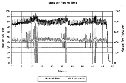
4.3.1 Mass A ir F lo w ... 68
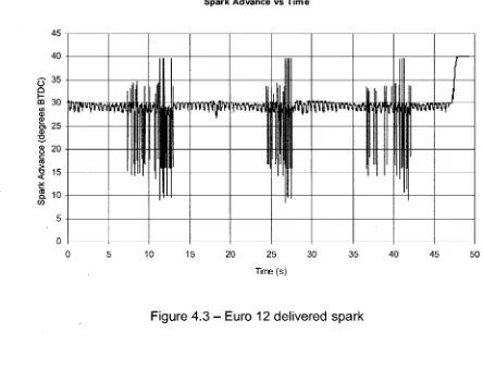
4.3.2 Ignition Tim ing... 69
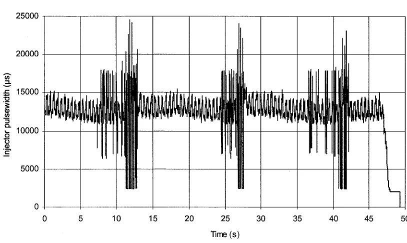
4.3.3 Fuel Injector Pulsewidth... 70
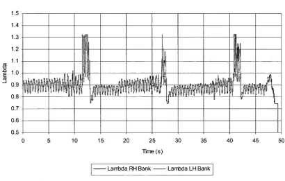
4.3.4 Exhaust Gas L a m b d a ... 71
4.4 Motorola System Results, Vehicle-level C alibration... 73
4.4.1 Corrected Brake T o rq u e ...73
4.4.2 Ignition Tim ing... 74
4.4.3 Fuel Injection...76
4.4.4 Exhaust Temperatures... 79
4.5 Motorola System Results - Modified C alibration...81
4.5.1 Corrected Brake T o rq u e ...81
4.5.2 Ignition Tim ing... 82
4.5.3 Fuel Injection...84
4.5.4 Exhaust Tem peratures... 86
5 CONCLUSIONS AND RECO M M ENDATIONS... 88
5.1 C onclusions...88
5.2 Future C onsiderations... ...89
R E FE R EN C E S ... 90
APPENDICES 1 Appendix A - Engine Specifications... 93
2 Appendix B - Transmission Specifications... 96
3 Appendix C - EFI System Wiring D etails... 97
4 Appendix D - Summary Table of Literature Reviewed... 111
LIST OF TABLES
Table 3.1 - EFI Euro 12 features... 44
Table 3.2 - 4R75W transmission states... 47
Table 4.1 - Test ambient conditions... 66
Table A.1 - Ford F-150 - 5.4L 3V engine specifications... 93
Table C.1 - Euro 12 driver connector wiring...97
Table C.2 - Euro 12 sensor connector w iring... 98
Table C.3 - Euro 12 and ETB module power and ground connections...100
Table D .1 a -S u m m a ry of Literature Reviewed... 111
LIST OF FIGURES
Figure 1.1 -T o rq u e curves fo r six identical engines...2
Figure 2.1 - Bosch fuel injector cutaway view [1] ...7
Figure 2.2 - Electronic throttle b o d y ... 8
Figure 2.3 - Variable camshaft timing m echanism ...10
Figure 2.4 - Intake charge motion control valve (a) closed, (b) o p e n ... 11
Figure 2.5 - (a) Electrohydraulic and (b) Electromagnetic valve actuators 15 Figure 2.6 - Saab variable compression ratio concept (a) 8:1, (b) 14:1... 17
Figure 2.7 - Ford 5.4L 3V crankshaft and camshaft position signals... 21
Figure 2.8 - Ford integrated mass airflow /intake air tem perature se n so r...22
Figure 2.9 - Typical ionization current waveform [14]... 28
Figure 2.10 - Model-based adaptive control system... 40
Figure 3.1 - Simplified test setup... 43
Figure 3.2 - (a) EFI Euro 12 engine control unit, (b) ETB m o d u le ...45
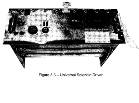
Figure 3.3 - Universal Solenoid D riv e r... 46
Figure 3.4 - PC interface for Universal Solenoid Driver c o n tro l... 47
Figure 3.5 - 4R70W transmission schem atic... 48
Figure 3.6 - Meiden FREC AC dynam om eter... 50
Figure 3.7 - Meiden dynamometer power and torque curves [2 9 ]...50
Figure 3.8 - Accelerator pedal position sensor transfer fu n c tio n s ...52
Figure 3.9 - Standard throttle position sensor transfer fu n ctio n s... 53
Figure 3.10 - Throttle position sensor wiring to achieve positive s lo p e ...53
Figure 3.11 - Throttle position with reversed sensor polarity...54
Figure 3.12 - Engine coolant temperature sensor transfer function...55
Figure 3.13 - Mass a irflo w sensor transfer function... 56
Figure 3 . 1 4 - Intake air tem perature sensor transfer fu n c tio n ...56
Figure 4.1 - Euro 12 calculated speed and synchronization error c o u n t...68
Figure 4.2 - Euro 12 measured mass a ir flo w ... 69
Figure 4.3 - Euro 12 delivered sp a rk...70
Figure 4.4 - Euro 12 open-loop fuel injector pulsew idth...71
Figure 4.5 - Euro 12 measured exhaust gas lam b da... 72
Figure 4.6 - Engine torque output with vehicle-level c a lib ra tio n ... 74
Figure 4.7 - Spark advance with vehicle-level calibration... 75
Figure 4.8 - Spark advance added to base calculation...76
Figure 4.9 - Open-loop target la m b d a ... 77
Figure 4 .1 0 -A c tu a l exhaust lambda, RH bank... 78
Figure 4.11 - Actual exhaust lambda, LH b a n k ... 79
Figure 4.12 - Exhaust gas temperature, RH bank...80
Figure 4.13 - Exhaust gas temperature, LH bank...80
Figure 4.14 - Engine torque output with modified ca lib ra tio n ...82
Figure 4.15 - Spark advance with modified calibration...83
Figure 4.16 - Spark advance added to base calcu la tion...83
Figure 4.17 - Open-loop target la m b d a ... 84
Figure 4.18 - Actual exhaust lambda, RH bank... ..85
Figure 4.20 - Exhaust gas temperature, RH bank...87
Figure 4.21 - Exhaust gas temperature, LH bank... 87
Figure A.1 - Ford 5.4L 3V engine cutaway view ... 94
Figure A.2 - Ford 5.4L 3V brake torque and horsepower [30],...95
Figure B.1 - 4R75W transmission cutaway view and power flow d ia gra m 96 Figure C.1 - 5.4L 3V harness to EFI Euro12 pin-out d ia g ra m ...105
Figure C.2a - Euro 12 distribution box... 106
Figure C.2b - Euro 12 distribution box...107
Figure C.3 - Lambda sensors to 14-19 Amphenol connector wiring... ...108
Figure C . 4 - Engine auxiliary to 14-18 Amphenol connector w iring...109
LIST OF EQUATIONS
Eq 2.1 - Ideal Gas Law... 31
Eq 4.1 - Brake power calculation... 65
Eq 4.2 - Horsepower conversion...65
Eq 4.3 - Horsepower conversion (sim p lifie d )... 65
Eq 4.4 - Power correction factor...65
Eq 4.5 - Corrected brake power... 66
NOMENCLATURE
AC Alternating current
ADACS Automated Data Acquisition and Control System
CAN Controller area network
CO Carbon monoxide (regulated tailpipe emission)
COP Coil-on-plug
DC Direct current
ECU Electronic [engine] control unit
EGR Exhaust gas recirculation
ETB Electronic throttle body
ETC Electronic throttle control
EVO/EVC Exhaust valve opening/closing (degrees crankshaft angle)
HEGO Heated exhaust gas oxygen sensor (switching type)
IVO/IVC Intake valve opening/closing (degrees crankshaft angle) Lambda ( X ) Actual air-fuel ratio divided by stoichiometric air-fuel ratio
LBT Leanest fuel for best torque
MBT Minimum spark advance for best torque
NOx Oxides of nitrogen (regulated tailpipe emission)
NTC Negative temperature coefficient (thermistor)
NVH Noise, vibration and harshness
OBD-II On-Board Diagnostics II
PCM Powertrain control module
PID Proportional, integral and derivative (control system)
SAE Society of Automotive Engineers
TDC/BDC Top-dead centre/bottom-dead centre (piston position) May be preceded by B (before) or A (after)
THC Total hydrocarbons (regulated tailpipe emission)
TWC Three-way catalyst
UEGO Universal exhaust gas oxygen sensor (lambda sensor)
1 INTRODUCTION
1.1 Introduction
Production vehicles utilize engine control strategies with a number o f adaptive
functions to improve drivability, as well as diagnostic and protection functions to
prevent engine damage. While these features may be desirable to the customer,
they introduce challenges for dynamometer testing. Adaptive and protective
controls can significantly alter fundamental operating parameters such as ignition
timing and fuel injection, generating variability in engine performance. It would
be beneficial to implement a simplified engine management system that delivers
consistent and repeatable performance.
Prior to the introduction of “variable” engine technologies, engine management
systems were far less complex. Ignition and fuel delivery were mapped at each
engine speed and load point, and sensor inputs were used to modify the
calculations. However, calibration of every possible condition on today’s engines
would be far too time consuming. Instead, torque demand-based strategies and
feedback schemes are used to reduce development time. Bypassing adaptive
and protective functions in modern torque-based control strategies is not a
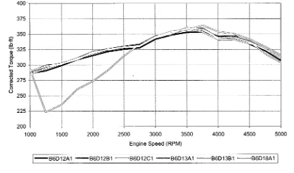
Figure 1.1 shows wide-open-throttle torque output from six identical V8 engines
run with the production engine control strategy. The large discrepancies are
attributed to adaptive and protective control functions.
5.4L 3V Torque Curves - Production Strategy
400
375
350
325
o
3
g-O
h- 300
-" O0)
S 275 -o
O
250
225
200
2500 3000 3500 4000 4500 5000
1000 1500 2000
Engine Speed (RPM)
— -B6D 12A1 — — B6D12B1 = ^ B 6 D 1 2 C 1 — B6D13A1 = B 6 D 1 3 B 1 = = B 6 D 1 8 A 1
Figure 1 . 1 - Torque curves fo r six identical engines
1.2 Engine Specifications
Testing has been carried out on Ford 5.4-litre V8 spark-ignited gasoline engines,
subsequently termed the Ford 5.4L 3V. Each cylinder head has a single
overhead camshaft and 3-valves per cylinder: two intake valves and one exhaust
valve. The engine utilizes coil-on-plug ignition, port fuel injection, electronic
throttle control, variable camshaft timing, and intake charge motion control
valves. A cutaway view and detailed engine specifications have been provided in
1.3 Transmission Specifications
To perform powertrain NVH testing, both the engine and transmission must be
installed in the dynamometer cell. In 2006 light-duty truck applications, the 5.4L
3V engine is mated to a 4R75W four-speed automatic transmission. Two
electronic shift solenoids and a mechanical gear selector spool valve direct the
fluid pressure through a valve body. This fluid pressure then actuates the
various transmission holding components such as bands and clutch packs, which
direct torque through planetary gear sets. A cutaway view and power-flow
diagram can be found in Appendix B.
1.4 Electronic Engine Control Systems
Good component design is the foundation for engine performance, however,
without precise control of airflow , fuel delivery and ignition timing, the engine’s
potential power output, fuel economy and emissions may never be realized. The
engine management system collects data from the various sensors, and makes
decisions on actuator functions to provide this precise control. Ford uses a
Motorola Black Oak powertrain control module for its full-size light-duty pickup
truck applications.
1.5 Research Objectives
The main objective of this research is to improve repeatability of engine
performance by implementing a simplified engine management system. More
1. Duplicate the wide-open throttle performance of the production strategy
while improving repeatability. The testing involves measuring the output
torque of several engines over their entire speed range with the complete
air induction system installed and no exhaust restriction.
2. Capability to perform part-load and no-load sweeps from idle to maximum
speed.
3. Achieve a stable idle at the same speed used in-vehicle.
1.6 Thesis Outline
The literature review section examines various sensor and actuator technologies,
as well as control strategies. Details for implementing a generic engine controller
and performing dynamometer testing are presented in Chapter 3. Chapter 4
discusses the results of testing with the generic controller and production system,
2 REVIEW OF LITERATURE
The following sections discuss the sensors and actuators used on the subject
engines, as well as their interactions within the control strategy. Alternatives to
these components and more recent technological advancements are also
presented. A great deal o f research has focused on innovative sensors and
actuators, online measurement and sophisticated control algorithms, however
comprehensive explanations of research-oriented engine controller applications
were scarce.
2.1 Engine Actuators
Actuators perform tasks as commanded by the electronic control unit. Their
functions include igniting the compressed air-fuel mixture, controlling the air and
fuel flow into the engine, regulating exhaust gas recirculation, and controlling the
camshaft timing. The following sections describe the actuators and control
system interactions used with Ford’s 5.4L 3V engine.
2.1.1 Coil-On-Plug Assem bly (COP)
The inductive coil assembly generates the high voltage necessary to ionize the
spark plug gap. It consists o f a primary winding and a secondary winding with 75
times as many turns. A low voltage is supplied to the primary winding and is
suddenly disrupted by the electronic control unit. The collapsing magnetic field
the large turns ratio), on the order of 30 kV. This high voltage is supplied across
the spark plug gap, causing an electrical arc. The air-fuel mixture subsequently
ignites and a flame propagates away from the spark plug electrodes. In a coil-
on-plug system, the coil assembly sits directly atop the spark plug. This replaces
older distribution systems in which a single coil (or multiple coils) generated the
high voltage, which was then delivered to the spark plugs by large, heavily
insulated wires.
2.1.2 Fuel Injector
A fuel injector is simply a solenoid-controlled valve (Figure 2.1). When the coil is
energized, a plunger is lifted off its seat and fuel is sprayed through an orifice into
the intake port. This orifice may be formed around the plunger as it opens, or a
fixed orifice may exist downstream of the plunger. A spring returns the plunger to
its “closed” position when the coil is de-energized.
In “return” fuel systems, the fuel rail supplies fuel to the injectors at a constant
pressure relative to the intake manifold pressure; therefore the quantity o f fuel
injected depends only upon the injector opening duration (pulsewidth). Excess
fuel is returned to the fuel tank. Conversely, “returnless” fuel systems require a
pressure sensor to measure differential pressure between the fuel rail and intake
manifold. The engine control unit then compensates for this difference by
making corrections to the injector pulse width. The Ford 5.4L 3V uses a
Figure 2.1 - Bosch fuel injector cutaway view [1]
Injection timing and spray characteristics ultimately impact performance,
emissions and fuel consumption. Ideally, all the injected fuel would vaporize in
the air charge, and the resulting mixture would be homogeneous prior to ignition.
However, practical challenges such as atomization, fuel wall impingement, and
air charge motion must be considered when designing injectors and ports. Early
injection (prior to intake valve opening) can aid in fuel vaporization and valve
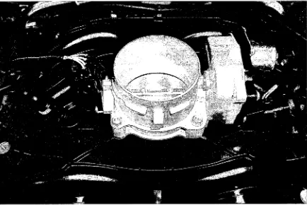
2.1.3 Electronic Throttle/Throttle-By-Wire
The electronic throttle body looks similar to a conventional throttle body, except
that the throttle cable has been replaced an electric actuation device, such as a
DC electric motor (Figure 2.2). Idle air bypass valves and cruise control
actuators are no longer needed since a throttle angle can be commanded
electronically. In “torque-based” engine management strategies, the throttle
plate does not follow the accelerator pedal position; rather, it is commanded by
the electronic control unit to provide a desired engine output torque.
2.1.4 Variable Camshaft Timing System (VCT)
Variable cam shaft timing enables phase shifting of the valve events relative to
the crankshaft angle. On the test engine, timing chains drive hydraulic camshaft
phasers, which subsequently drive the single-overhead camshafts. An electric
solenoid and valve body assembly direct engine oil pressure through the
camshaft to the phaser, either advancing or retarding the camshaft timing as
desired (Figure 2.3).
With single overhead camshafts, intake and exhaust valve events are phased
equally (termed dual-equal VCT, DEVCT). At part-throttle, the valve events are
significantly retarded to achieve the following:
o Delayed valve overlap for increased residual dilution and pumping work
reduction
o Delayed intake valve closing (IVC) for pumping work reduction, in spite of
a lower effective compression ratio,
o Delayed exhaust valve opening (EVO) for increased expansion work.
The main benefits of variable camshaft timing are reduced NOx emissions via
internal exhaust gas recirculation, and improved fuel economy. An added benefit
is the ability to eliminate external EGR systems for a significant reduction in
Valve Body Assembly
Cam shaft r S /
Phaser
Figure 2.3 - Variable camshaft timing mechanism
2.1.5 Charge Motion Control Valves (CMCV)
Charge motion control valves are located in each intake manifold runner (Figure
2.4). As the name suggests, these valves alter the motion of the intake air
charge, creating swirl and tumble that persists through combustion. By means of
intensive charge motion, the ignition delay and burning duration can be
significantly reduced. The resulting combustion stabilization effect leads to higher
EGR tolerance and lean burn capability. Fuel economy and emission
improvements also result from the lower enrichment requirements during cold
start and warm-up, and improved combustion stability allows fuel savings through
reduced idle speed.
The use of a control valve to induce swirl and tumble in the intake ports has the
area. This is compensated by more efficient combustion (faster burn rate)
allowing a higher torque to be generated at low engine speeds and loads. As the
engine speed and load are increased, a point is reached such that the pumping
losses associated with the closed valve outweigh the benefits of a faster
combustion rate. At this point, the valves are opened and the resulting higher
volumetric efficiency allows more torque to be developed [2],
Figure 2.4 - Intake charge motion control valve (a) closed, (b) open
2.1.6 Electric Radiator Cooling Fan
When the vehicle speed is not sufficient to force air flow through the radiator,
electric fans may be used to draw air through. Electric fans are switched on
when the inferred engine coolant temperature reaches a predefined threshold.
2.1.7 Mechanical Actuators
Some engine components are not thought of as actuators since they act
mechanically, and have no interaction with the electronic controller. Examples
include:
o Valvetrain - valves are mechanically actuated by camshafts and springs
o Thermostat - material thermal characteristics cause the thermostat to
open
o W ater pump - usually driven proportional to the crankshaft speed by an
accessory belt
Greater thermal efficiency and reduced parasitic losses can be realized if these
components are electrically actuated. A more detailed discussion is presented in
the following section.
2.2 Advancements in Actuator Technologies
Emerging actuator technologies have enabled the continued improvement of
internal combustion engine efficiency.
2.2.1 Electromechanical Valve Actuation (EVA)
Using camshafts to actuate valves, even with variable cam timing, requires many
compromises to achieve good performance, fuel economy and emissions.
Electromechanical valve actuation gives the engine designer freedom to choose
the best valve timing and lift profile for each engine operating condition.
Additionally, EVA enables unthrottled operation since engine load may be
controlled with early intake valve closing. Therefore pumping losses are
reduced, and torque response time is drastically improved because there is no
intake manifold filling delay. Simplicity of cylinder deactivation is another
Full-load performance is enhanced through optimized volumetric efficiency,
optimized expansion work and minimized exhaust residuals. At high engine
speeds, late intake valve closing takes advantage of the charge momentum to
continue filling the cylinder as the piston begins to rise. Intake valve closing can
be advanced at lower speeds to prevent the charge from being pushed back out
past the intake valve. Additionally, faster valve movement as compared to cam-
driven systems allows for longer durations at full lift [3]. Exhaust valve open
timing is a compromise between maximizing expansion work and minimizing
exhaust gas pumping expenditure. By opening the exhaust valve prior to bottom-
dead-centre on the expansion stroke, high-pressure exhaust gases flow out of
the cylinder. Termed “blowdown”, this reduces the piston effort necessary to
push the remaining exhaust gases past the valve. Since there is less time for
blowdown at higher speeds, earlier exhaust valve opening can be advantageous.
At low speeds, exhaust valve opening may be delayed for increased expansion
work, while maintaining ample time for blowdown. Again, electromechanical
actuators may open valves faster than a camshaft, so the exhaust valve opening
can be further delayed at all speeds. The valve overlap between exhaust and
intake strokes dictates the amount of residual exhaust gas left in the cylinder.
Minimizing exhaust residuals at full load allows more fresh air to be inducted,
resulting in higher torque.
Charge air motion control is another important benefit of electromechanical valve
raise inlet velocities and generate turbulence, resulting in a faster burn and less
cycle-to-cycle variation. This improves thermal efficiency and combustion
stability. Utilizing low lifts and slower valve movement also reduces valvetrain
power consumption. In an engine with two or more intake valves per cylinder, air
motion can be further manipulated by independently varying the lift and timing of
each intake valve [3].
Internal exhaust gas recirculation can be accomplished by early exhaust valve
closing to trap residuals, or by holding the exhaust valve open during the early
part of the intake stroke to draw exhaust gases back into the cylinder. The inert
exhaust dilutes the fresh intake charge, suppressing combustion temperatures
for less NOx formation. At idle, residual fraction can be minimized for best
combustion stability.
Two types of valve actuators have been studied extensively: electro-magnetic
and electro-hydraulic actuators. Schechter and Levin of the Ford Research Lab
investigated the electro-hydraulic concept using a hydraulic pendulum [3],
illustrated in Figure 2.5a. A small double-acting piston is fixed to the top of each
valve and rides in a sleeve. The volume above the piston can be connected to
either a high- or low-pressure source through solenoids and check valves, while
the volume below the piston is constantly connected to the high-pressure source.
The pressure area above the piston is significantly larger than below the piston,
decelerate. Theobald et al. of General Motors detail an electromagnetic
actuation concept [4], which uses a permanent magnet and plunger with an
electrical coil and compression spring both above and below the plunger (Figure
2.5b). Energizing either coil pulls the plunger toward that coil, against the
compression spring force. W hen de-energized, the stored spring energy
accelerates the plunger away from the coil. Steve Beard o f Taylor Engineering
has developed spring-less electromagnetic valve actuators based on linear
motor/generator principles. An integrated position sensor enables closed-loop
valve position control [5]. Cost, durability and noise are the present barriers
facing electromechanical valve actuation in mass production.
HIGH PRESSURE CHECK VALVE TO AND FROM HIGH PRESSURE SOURCE
HIGH PRESSURE SOLENOID
LOW PRESSURE CHECK VALVE
TO AND FROM LOW PRESSURE SOURCE
LOW PRESSURE SOLENOID
Spring A
Coil A
Airgap A
Plunger
Magnet
Airgap B
Coil B Spring B
Core
Valve Guide
Valve
(a) (b)
2.2.2 Variable Compression Ratio Mechanisms (VCR)
Increasing the compression ratio of an internal combustion engine results in
higher thermal efficiency. However, fuel properties impose practical limitations
on compression ratios: there is a greater tendency for combustion knock with
higher in-cylinder temperatures. Since in-cylinder temperatures are proportional
to the engine load, variable compression engines can take advantage of high
compression at light loads and reduce the compression ratio at higher loads to
prevent knock.
In order to achieve variable compression, there must be a method of actively
changing the cylinder clearance volume. Several possibilities exist, although
some are hindered by practical design constraints.
o Moving the cylinder head with respect to the crankshaft axis
o Varying the connecting rod length
o Varying the crankshaft stroke (also affects displacement)
o Varying the piston deck height
o Using a secondary piston in the combustion chamber
The best-known production application of variable compression is the Saab 1.6L
supercharged engine. In this engine, the cylinder block is hinged above the
crankcase. When the upper half is tilted, the cylinder block and head assembly
2.6). This system is capable of varying the compression ratio between 8:1 and
14:1 [6].
(a) (b)
Figure 2.6 - Saab variable compression ratio concept (a) 8:1, (b) 14:1
2.2.3 Cylinder Deactivation/Variable Displacement
The ability to deactivate specific intake and exhaust valves along with their
corresponding fuel injectors can reduce the effective displacement of an engine
for fuel savings under light load conditions. With valves deactivated, gases
trapped in the cylinder are repeatedly compressed and expanded, with a small
energy loss to heat transfer and friction. For normal operation to resume, the
stored gas must be expelled through the exhaust valve and a fresh air-fuel
charge inducted during the subsequent intake stroke. Disabling fuel injectors
without disabling the valves would cause high exhaust gas oxygen
concentrations, rendering three-way catalytic converters ineffective.
General Motors’ Active Fuel Management™, formerly called Displacement on
supply to specific lifters in a pushrod V-engine, thereby de-activating the
respective intake and exhaust valves. Technologies such as electronic throttle
control and sequential port fuel injection facilitate a seamless transition between
operating modes [7]. DaimlerChrysler implemented the Multi-Displacement
System™ on its Hemi® pushrod engine and Active Cylinder Control™ on
Mercedes V12 engines [8]. Both systems operate on similar principles to Active
Fuel Management™. Unlike the aforementioned systems, Honda’s Variable
Cylinder Management™ is implemented on overhead camshaft engines. It uses
a solenoid to unlock the cam followers from their respective rockers on one
cylinder bank, so the cam followers float freely while the valve springs keep the
valves closed [9].
2.2.4 Electronically Controlled Engine Cooling
Cooling systems must be designed with the capacity to manage worst-case
engine cooling requirements. In conventional designs, the coolant pump is
driven proportional to crankshaft speed, regardless of the engine load. This
causes unnecessary parasitic losses at low loads. An electric coolant pump,
which is controlled independently of engine speed, is available on current
production BMW six-cylinder engines. In addition to the obvious fuel economy
and performance benefits, this feature provides faster engine warm-up, and
enables coolant circulation for the climate control system without running the
Unlike melting wax type thermostats, electric thermostats enable variable
operating temperatures, more accurate temperature control, proactive response
capability and self-diagnostics. At higher temperatures, friction is reduced due to
lower oil viscosity, and thermal efficiency improves because less combustion
heat is lost to the combustion chamber surfaces. Two important trade-offs exist
at higher operating temperatures: increased NOx formation and slightly reduced
wide-open throttle brake mean effective pressure [2].
2.2.5 42-Volt Electrical System
As mechanical systems are increasingly replaced with electronic actuators, the
electrical system will have to be upgraded to provide the necessary power. The
practical limit for present 14V electrical systems is approximately 3kW, but
combining technologies such as electromechanical valve actuation, electric water
pumps, electric assist power steering and active ride control will require 4-5kW.
Transition to a 42V electrical system will make this possible. Another potential
benefit is the introduction of an integrated alternator-starter-flywheel, which would
effectively elim inate the front-end accessory drive system [10].
2.3 Engine Sensors
Several sensors are necessary for modern electronic engine control. The
following sections describe the sensors used on the Ford 5.4L 3V engine, and
2.3.1 Crankshaft Position Sensor
Precise crankshaft position measurement is the foundation for achieving good
ignition and fuel injection timing control. The test engine uses a 36-tooth wheel
affixed to the crankshaft and a stationary inductive sensor to determine
crankshaft angular position. As the teeth pass by the sensor, a sinusoidal
voltage signal is generated, shown in Figure 2.7. Each falling-edge zero crossing
corresponds to 10° of crankshaft rotation. There is one missing tooth used as a
position reference. For example, the missing tooth may pass the sensor every
time piston #1 reaches its top-dead-centre position. The time between zero-
crossings indicates the engine speed.
2.3.2 Camshaft Position & Cylinder Identification Sensor
Another inductive sensor is needed to determine the camshaft position. Since
the crankshaft position sensor wheel completes two revolutions during the four-
stroke cycle, it cannot identify the engine stroke. The camshaft makes one
revolution per four-stroke cycle; therefore a camshaft position sensor can identify
the stroke. For example, a pulse could be generated every time piston #1
reaches top-dead-centre on its compression stroke. This information is needed
to initialize the ignition and fuel injection sequence. With the addition of variable
camshaft timing, the camshaft position sensor also provides feedback to the
engine controller regarding the actual cam phase angle with respect to the
Crankshaft and Camshaft Position Signals
3
Camshaft “Extra Tooth’ (10° ATDC #1 Firing)
2
1
o >
Q_
e
<
•2
Crankshaft “missing
tooth” (60° BTDC #1) — Crankshaft Position Signal — Camshaft Position Signal
-3
540 630
90 180 270 360 450 720
0
Crankshaft Angle (Degrees)
Figure 2.7 - Ford 5.4L 3V crankshaft and camshaft position signals
2.3.3 Mass Air Flow Sensor
To calculate fuel injection quantities, it is necessary to measure the mass of fresh
air drawn into the engine. In the mass air flow sensor, a heated platinum wire is
suspended in a small channel so that only a portion of the main intake a irflo w is
measured (Figure 2.8). As the air passes over the hot wire it tries to cool the
wire and change its resistance. By running the sensor in a closed-loop bridge
circuit, an output signal of many volts can be obtained by a current change in the
device in the range of 0.5 to 1.5A. The small size of the element makes the
milliseconds, which is one of the attributes needed fo r refined control of fuel
injection. It is also fundamentally responsive to mass flow and not volume flow
and therefore needs no further compensation for ambient air conditions [11].
Intake pressure waves cause reverse-flow across the element, resulting in
artificially high measurements and signal oscillation; therefore appropriate signal
processing must be used.
INTAKE AIR FLOW
Figure 2.8 - Ford integrated mass airflow /intake air temperature sensor
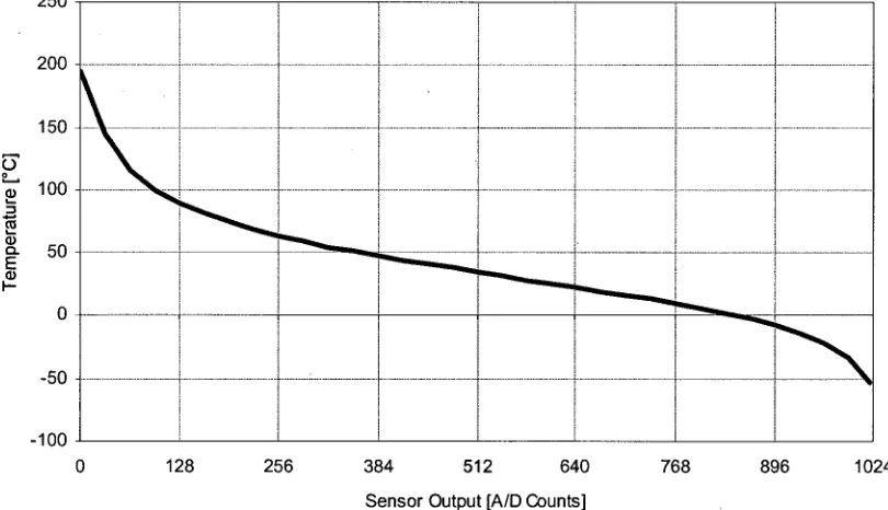
2.3.4 Intake Air Temperature Sensor
A negative temperature coefficient (NTC) thermistor is integrated within the mass
air flow module to measure intake air temperature. A NTC thermistor is
temperature. Thermistors give a relatively large change in resistance for a small
temperature change, and are useful for applications with a specified temperature
range and where interchangeability without recalibration is required [12]. The
temperature of air inducted into the cylinders directly influences combustion
temperatures and the probability of mixture self-ignition. Since ignition timing
also affects combustion temperatures, the measured air temperature is used as a
modifier in the ignition timing calculation. For example, retarding the ignition
timing in hot ambient conditions helps to suppress combustion temperatures and
prevent knocking.
2.3.5 Cylinder Head Temperature Sensor
Another sensor is needed to infer the engine coolant temperature. A NTC
therm istor is threaded into the cylinder head and measures the metal
temperature between a pair of valves. This location shows good correlation with
coolant temperature due to high heat transfer under most operating conditions
[2]. As a replacement for direct coolant temperature measurement, this sensor is
not exposed to a harsh fluid operating environment, is not susceptible to fouling,
and is less sensitive to coolant tem perature fluctuations upon thermostat
opening. The inferred coolant temperature aids in decisions concerning cold
start and warm-up operation, electric cooling fan operation and engine protection
in the event of coolant loss. A cold engine suffers from poor combustion stability,
2.3.6 Oil Temperature Sensor
A third NTC thermistor monitors the engine oil sump temperature. Oil
tem perature must be known for proper operation of the variable camshaft timing
mechanism and for engine protection logic.
2.3.7 Switching Exhaust Gas Oxygen Sensors
To enable the use of three-way catalysts (TWC), closed-loop air-fuel ratio control
around stoichiometry (A,=1) is necessary. This means that actual air-fuel ratio
feedback must be provided to the engine controller so that fuel adjustments can
be made.
Switching exhaust gas oxygen sensors are able to distinguish between lean and
rich burn conditions by detecting the presence or absence o f oxygen in the
exhaust gas. Two types are in common use, one based on Zirconium Oxide
(Zirconia) and the other on Titanium Oxide (Titania). In the Zirconia device, the
material is formed into a ceramic tube with electrodes on the inside and outside.
The inside is in contact with ambient air, which acts as a "reference" and the
outside is in contact with the exhaust gas. When the sensor is at high
tem perature (300°C), a large imbalance in oxygen across the ceramic wall
generates a small voltage, typically 0.8V. As soon as there is free oxygen in the
exhaust this voltage falls to nearly zero, hence the term “switching” oxygen
In the Titania sensor there is a different mechanism at work but the result is
much the same. Again, at high temperature, Titania behaves as a
semiconductor material whose resistance is dependent on the oxygen content of
the gas surrounding it. With a rich mixture and low oxygen content the
resistance is a few ohms but as soon as the oxygen content increases the
resistance increases dramatically to greater than 10 kQ. By placing the sensor in
series with a fixed resistor, it is possible to create a change in output voltage as
the exhaust gas passes through the stoichiometric point in a similar fashion to
that of the Zirconia sensor.
With the lag of the transport time for the gases to pass through the engine and
exhaust system, the response time of the sensor itself and the highly non-linear
signal from the sensor, it will be appreciated that this is not a very desirable set of
characteristics to achieve stable a closed-loop control system. And indeed the
result is that the closed-loop system is in fact allowed to oscillate between slightly
rich and slightly lean settings. Fortunately, the three-way catalyst is most
efficient under these conditions [11].
There is an oxygen sensor located in the collector pipe for each bank of
cylinders. Unless adaptive control algorithms are used to compensate for
injector flow variations, all injectors in the cylinder bank use the same duration.
Since they rely on high operating temperatures, oxygen sensors may be
2.3.8 Knock Sensors
A knock sensor is simply an accelerometer used to detect combustion knock
through cylinder block vibration. Since the excitation frequency caused by
combustion knock is known, a band-pass filter can be used to isolate knock from
other structural vibrations. Typical knock control strategies substantially retard
ignition timing at the first occurrence of knock, and then gradually advance the
timing to its original state. Retarding ignition timing has a severe impact on
engine torque and exhaust temperatures, so for dynamometer testing, it may be
desirable to alert the operator when knock is detected, but not automatically
modify the ignition timing as a result.
2.3.9 Accelerator Pedal Position Sensor
Three rotary potentiometers measure the position of the accelerator pedal. Two
sensors are redundant, and are used to diagnose system malfunctions and
ensure occupant safety. The amount of torque demanded by the driver is
inferred from the accelerator pedal position.
2.3.10 Throttle Position Sensor
Position o f the throttle plate is commanded by the engine management system
and controlled by an electric motor; however, redundant throttle position sensors
are required to verify proper system operation. Two rotary potentiometers,
2.4 Alternative Sensors
As “variable” engine technologies continue to emerge, more sophisticated online
measurement capability will be necessary. Increased use of closed-loop control
will reduce calibration time and lead to more robust systems. The following
sections examine alternatives to the Ford 5.4L 3V engine sensors discussed
above, as well as innovative sensor technologies that are being researched.
2.4.1 Ionization Current Sensing
The most robust engine control strategies would be based on direct
measurements of the combustion process. Ideally, there would be a pressure
transducer in each combustion chamber and model-based control could be used
to optimize combustion in real time. Since this is currently cost-prohibitive for
mass production, ionization current sensing may be a promising, although
somewhat less capable alternative. Much research has been carried out on in
cylinder ionization current measurement using the spark plug as a sensor. The
potential for detecting misfire, knock, air-fuel ratio, peak pressure position,
camshaft phase and predicting emissions have been recognized.
The ion current is a complicated signal consisting of three components: the
ignition phase, the flame front phase and the post-flame phase (Figure 2.9). It is
generally accepted that the H30 + ion is the primary chemi-ion produced in the
reaction zone, and that the NO ion is the dominating source for formation of free
together with low values of spark advance, and also with light engine loads and
low air-fuel ratios [13]. It should also be noted that the ion current sensor
provides a spatially local measurement that does not represent the overall
mixture properties in the combustion chamber. Spatial inhomogeneities of
temperature and composition from cycle to cycle can cause substantial variations
in ion current signals [13].
Ionization Current 3.5
Post-Flame Phase
Ignition Phase Flame-Front
Phase 2.5
c
£
b.
D o
0.5
10 30 40 50
-2 0 -1 0 0 20
-3 0
Crank Angle [deg]
Figure 2.9 - Typical ionization current waveform [14]
The flame-front phase of the signal has shown strong correlation with air-fuel
ratio [15, 16, 17], while the post-flame phase corresponds to cylinder temperature
[13]. The post-flame ion current peak location can be used as feedback to adjust
ignition timing [18]. Optimal torque output was observed when the ion peak was
controlled at 15° after TDC. If the peak arrives earlier, work is lost due to heat
transfer and compression; and if the peak arrives too late expansion work is lost.
Knock and misfire detection are more trivial. When a misfire occurs, only a
therefore a much more robust detection technique than crankshaft velocity
fluctuation measurements. Combustion knock causes rapid oscillations in
cylinder pressure and temperature at a characteristic frequency. This oscillation
is also evident in the ion current signal, and using appropriate filtering, a knock
threshold can be defined.
Saab, Caterpillar and Adrenaline Research have applied ion current
measurement for com mercially available products. Saab uses the spark plug as
an ionization sensor for misfire detection [17]. Caterpillar uses an ionization
probe in its lean burn engines to estimate air-fuel ratio. The probe is located
some distance from the spark plug and uses the flame arrival time as an
indication of air-fuel ratio [17]. The SmartFire® by Adrenaline Research claims to
be the first ignition system capable of closed-loop ignition and fuelling control for
each cylinder while also detecting misfire and knock [19]. Like the Saab system,
it uses the spark plug as an ionization sensor.
2.4.2 Wideband Oxygen Sensor/Lambda Sensor
In a wideband air-fuel ratio sensor, the oxygen-sensing Nernst cell described in
section 2.3.7 is combined with an oxygen pump to create a device that can
measure actual air-fuel ratios. The oxygen pump uses a heated cathode and
anode to pull some oxygen from the exhaust into a diffusion gap between the two
components. The Nernst cell and oxygen pump are wired together in such a way
is directly proportional to the oxygen level in the exhaust gas. In rich conditions
(A.<1) a negative current is produced, while in lean conditions (X>1) a positive
current is produced [20].
For automotive manufacturers, switching oxygen sensors are adequate for three-
way catalyst operation, but they do not provide useful feedback in rich or lean
conditions. Open-loop fuel control is used during warm-up and at wide-open
throttle, where rich conditions are necessary. Cold start-up is a major source of
emissions, namely unburned hydrocarbons and carbon monoxide. As emission
legislation becomes increasingly stringent, feedback control at start-up and wide-
open throttle may become necessary.
Lean burn spark-ignition engines are under development and have the potential
to significantly improve fuel consumption. Their drawback is that three-way
catalysts will not effectively reduce emissions. Control of aftertreatment devices
such as lean NOx traps will require online air-fuel ratio measurement using
wideband oxygen sensors. As previously mentioned, in-cylinder ion probes may
also be useful in balancing cylinder-to-cylinder air-fuel ratios.
2.4.3 Position Sensors
Traditional variable reluctance sensors have some shortcomings: their signal
magnitude is proportional to speed, and they are sensitive to vibrations and
suffer these disadvantages, although they tend to be more costly and require
conditioning electronics. Magneto-resistive sensors have the added benefits of a
much larger intrinsic signal and higher temperature range than silicon-based Hall
effect sensors. General Motors [21] developed a position measurement
technique using two low-cost magneto-resistive sensors and a trigger wheel with
complementary geometry. For example, while one sensor detects a trigger
wheel tooth the other sensor detects a slot. The waveform s cross at the
transition from tooth to slot, resulting in highly accurate position measurement
with little sensitivity to air gap. When used for camshaft position measurement, a
180° complementary trigger wheel design was able to identify the engine cycle at
power-on, thus initializing ignition and injection sequences earlier.
2.4.4 Manifold Absolute Pressure
Some manufacturers such as DaimlerChrysler use a speed-density calculation to
infer the mass of air inducted per stroke.
p v ^ ' (E q .2 .1 )
C l if r j - i
Where: Mair is the mass of air inducted into the cylinder
P is the absolute manifold pressure
Vcyi is the cylinder swept volume
rivoi is the volumetric efficiency
R is the gas constant for air
In the most basic sense, this requires measurement o f only the engine speed
(upon which volumetric efficiency depends) and manifold air pressure. Ambient
air temperature and pressure compensation improve the estimate, however
these are relatively slow-moving variables. Various modifiers are applied based
on ambient and engine conditions (including exhaust gas recirculation).
As the engine wears and ages, the accuracy of this calculation degrades.
Additionally, if modifications to the engine change its volumetric efficiency, the
reference tables must be updated. Therefore, it is much more beneficial to use a
mass a irflo w meter to directly measure the mass of air being inducted [11].
2.5 Control System Design
2.5.1 Open Loop Control
Open loop control systems are defined as “systems in which the output has no
effect on the control action” [22], Open loop, or feed-forward control is used in
engine control when feedback is not available. It involves using measurements
of the physical system, along with calibrated maps and transfer functions to
obtain a desired output. Perhaps the best example is air-fuel ratio control when
the exhaust gas oxygen sensors are not functional. Injection quantities are
calculated in a feed-forward sense based on the measured mass a irflo w and
2.5.2 Closed Loop or Feedback Control
Ogata defines a feedback control system as “A system that maintains a
prescribed relationship between the output and the reference input by comparing
them and using the difference as a means of control” [22].
Feedback control schemes are preferred to open loop controls, since they are
relatively insensitive to disturbances and do not require calibration. Some
examples of feedback control in automotive applications include electronic
throttle position and ignition timing for idle speed control, air-fuel ratio control
using exhaust gas oxygen sensor feedback, and vehicle speed control.
A sophisticated idle ignition trim algorithm uses crankshaft acceleration as
feedback to modulate the ignition timing. Global ignition timing is significantly
retarded from MBT at idle, and individual cylinder timing can be advanced or
retarded to equalize the acceleration generated by each cylinder. The result is
more refined idle speed control.
2.5.3 Proportional, Integral and Derivative Control
Proportional, integral and derivative (PID) controllers are used almost universally
in industrial control applications. Proportional action provides a contribution that
depends on the instantaneous control error, integral action gives a control output
that is proportional to the accumulated error, and derivative action depends on
proportional, integral and derivative gains are tuned to obtain the desired system
response and prevent instabilities.
2.5.4 Torque-Based Engine Management Strategies
In modern engine control strategies utilizing electronic throttle actuation, all
actuator functions can be based on a central engine torque requirement. This
consists of driver torque demand, accessory loading, idle speed control, traction
control, and vehicle speed control. In order to fulfill this torque requirement,
actions such as modifying ignition timing, camshaft phasing, fuelling or throttle
opening may be taken. This leads to reduced calibration effort when component
changes are made, enables a number of fuel saving and emission reduction
schemes, and facilitates traction control by limiting engine torque.
2.5.5 Adaptive or Learning Algorithms
Adaptive algorithms fine-tune actuator functions to the individual engine and
driver over a relatively long period o f time. For short-term dynamometer tests on
new engines, it is highly undesirable to use adaptive functions since they can
cause variability in testing. An example is adaptive fuel trim, which compensates
for injector deposits and reduced fuel flow over the life of a vehicle. If exhaust
gas oxygen sensors indicate a consistently lean condition, the controller will
adjust the baseline fuelling calculations for both open- and closed-loop modes.
Once this compensation reaches a predefined threshold, a diagnostic error is
2.5.6 Protective and Diagnostic Functions
Protective functions prevent engine damage due to symptoms such as
combustion knock, overheating, low oil pressure, excessive engine speed and
insufficient idle speed. Meanwhile, diagnostic features help to identify
com ponent failures that may impact emissions, fuel economy and performance.
On-Board Diagnostics II (OBD-II) continually monitors the engine for misfires,
catalyst efficiency, and proper fuel system and evaporative emissions system
operation [24].
Knock sensors have a great deal of authority over ignition timing. When knock is
detected from any cylinder, the global ignition timing is retarded to eliminate the
knock. For dynamometer testing and research purposes, it may be desirable to
detect the occurrence of combustion knock and alert the operator, but not
necessarily adjust ignition timing automatically.
Exhaust temperature models are used to protect the exhaust system
components from damage. These components include exhaust manifold
flanges, oxygen sensors and catalysts. Component temperatures are inferred
from operating parameters such as engine load, air-fuel ratio and ignition timing.
At high loads especially, a late spark raises the exhaust tem perature while an
early spark can cause knock. When the ignition timing is retarded for knock
prevention, fuel enrichment may be necessary to suppress exhaust
Excessive engine speed and vehicle speed (for tire protection) are prevented
using torque clipping features such as throttle and ignition cut-offs. Idle speeds
may be modified for engine warm-up, overheating prevention, electrical system
charging and various accessory loads such as the power steering pump and air
conditioning compressor. In cases of severe overheating or loss of oil pressure,
the engine may be forced into a “limp-mode” or shut down completely.
2.6 Advanced Control Algorithms
More sophisticated control algorithms can further enhance engine performance
by better estimating the engine operating conditions, often without the need for
additional engine sensors.
2.6.1 Model Based Control
Traditional methodology of map-based parameter storage and associated
correction factors is essentially empirical and must rely on considerable practical
testing of the system. The adoption of model-based control can substantially
ease these development challenges. In this technique, the controller relies not
just on the physical system information obtained from the sensors, but produces
a comparative picture of the system behaviour, using this to anticipate the likely
future. In this way, a number of advantages can be provided, at some cost of
2.6.2 Individual Cylinder Fuel Control
Kainz and Smith developed an algorithm to address cylinder-to-cylinder fuel
imbalance issues using the existing switching exhaust gas oxygen sensor [26].
This algorithm accounted for engine inherent imbalances such as intake air and
EGR distribution, as well as component variability such as fuel injector flow rates.
Their model considered fuel wall wetting dynamics, exhaust gas mixing, engine
cycling, gas transport and sensor delay, in order to correlate oxygen sensor
output to individual cylinder events. Due to processing limitations for time-based
samples, event-based sampling was necessary. The sensor bandwidth and
processing capabilities were sufficient to correct individual cylinder imbalances
up to 3000 RPM.
Observed benefits were reduced emissions, improved torque and fuel economy,
and less combustion variability for better idle quality and drivability. Diagnosis of
individual injector issues was another attribute of this system.
2.6.3 Crankshaft Velocity Fluctuation
Crankshaft velocity fluctuation measurement has been used extensively for
misfire detection. Under normal combustion, each cylinder’s firing event
contributes a small acceleration to the crankshaft to maintain a mean velocity.
When a misfire occurs, the affected cylinder contributes no acceleration and
individual cylinder ignition tinning can be tailored so that each combustion event
contributes an equal acceleration to the crankshaft. Ford uses this “idle ignition
trim ” feedback scheme to improve idle quality.
2.7 Engine Management Systems
A number of engine management systems were investigated to fulfill the
objectives of this research.
2.7.1 Ford Research Console (RCON)
The Ford RCON system is a DOS-based calibration tool, which has become
mostly obsolete for recent development programs. One exception is the 2005-
2006 Ford GT super-car. ATI Vision replaced RCON for gasoline engine
calibration within Ford.
2.7.2 Accurate Technologies, Inc. - ATI Vision
ATI Vision is the current calibration software package used for Ford gasoline and
European diesel engine programs. The software communicates with ATI
hardware, including memory emulators that plug into the engine controller. The
engine control strategy is programmed into the emulator and then run by the
controller. Vision’s intuitive graphical interface enables quick calibration
2.7.3 ETAS Integrated Calibration and Analysis (INCA)
ETAS INCA is used for Ford North American diesel engine programs. Sim ilar to
ATI Vision, INCA uses a graphical user interface to enable communications with
electronic hardware, modify calibrations and set up data acquisition. Its structure
is initially less intuitive than ATI Vision.
2.7.4 EFI Technology - EFI Communication Tool (ECT)
Although not as intuitive or visually appealing as ATI Vision, this basic software
tool enables the user to easily make calibration changes, program the controller
and set up data logging. Data can be viewed in real-time through user-
configurable displays. Controller logged data can be viewed in a separate
application, or exported to common file formats.
2.7.5 Research Based Engine Management Systems
Engine management systems have been developed for various research
applications; however, the details of such work are proprietary and thus not
widely available. Current diesel engine research at the University of W indsor
uses National Instruments hardware and LabVIEW software to provide real-time
model-based engine control. The system shown in Figure 2.10 consists of three
main parts:
o An FPGA card to generate digital pulse trains that act as input for the
injector power driver. The FPGA program is also responsible for crank-