770 00905 0370-VHBE_Ed_08 1 © 2001 Alcatel Bell N.V., All rights reserved
Intro to ADSL
Intro to ADSL
During class please
switch off
your mobile, pager or other that may interrupt.
Course objectives:
• The trainee will understand the working principles of ADSL.
• The trainee will get an overview of all the problems and solutions when using high bitrates on copper twisted pair.
Entry level requirements:
• Intro to ATM (GETE2441) => basic ATM for applications in adsl Suggested duration:
1/2 day Normal class hours 08:30h => 12:00h 13:00h => 16:30h
This presentation must be read in the PowerPoint SLIDE-SHOWmode, because it contains a lot of
770 00905 0370-VHBE_Ed_08 3 © 2001 Alcatel Bell N.V., All rights reserved © 2001, Alcatel Bell N.V. All rights reserved
Alcatel University Antwerp, page n° 3
Table of content
Table of content
Introduction Standards Restrictions Modulation Error detection and correction xDSL technologies
© 2001, Alcatel Bell N.V. All rights reserved
Introduction
Introduction
770 00905 0370-VHBE_Ed_08 5 © 2001 Alcatel Bell N.V., All rights reserved © 2001, Alcatel Bell N.V. All rights reserved
Alcatel University Antwerp, page n° 5
POTS modem communication
Frequencies within the voice band are transmitted through the
switched connection of a PSTN network.
This voice band is used for voice communication or modem
communication (i.e. fax, V.32, V.90, …)
WWW
NB Access server + modem pool
modem
PSTN network
© 2001, Alcatel Bell N.V. All rights reserved
Alcatel University Antwerp, page n° 6
POTS vs. non-POTS modem communication
DSL technologies use also other frequencies outside the voice
band to modulate information on your local telephone line.
ISDN provides you with a 160 kbps connection on your local line. ADSL provides you a high speed connection on your local line.
Frequency (fHz)
300Hz 3400Hz
Other frequencies used by DSL technologies: ISDN > up to 80kHz ADSL > up to 1,1MHz Voice band used by POTS modems (V.32, V.90, …)
770 00905 0370-VHBE_Ed_08 7 © 2001 Alcatel Bell N.V., All rights reserved © 2001, Alcatel Bell N.V. All rights reserved
Alcatel University Antwerp, page n° 7 PROBLEM
Bitrate of analogue
modem limited to 56 kb/s
PSTN not suited for
high speed data traffic
ADSL - modem
Redirection of data
traffic to specific
network (B-ISDN)
SOLUTION
Solutions offered by ADSL
Today we are facing 2 problems.
(1) The voice network, specifically designed to transport voice (using circuit switching) is not ideal to transport data. Mainly because of the bursty nature of data communication and the limited capacity of the voice network (64 kbps). That is why a B-ISDN was created.
(2) slow access: the capacity of an analogue modem is limited to about 30 kbps.
The solution to this problem is ADSL, where we extend the used frequency band to about 1MHZ.
V.90 technology is able to accelerate data downstream from the Internet to your computer at speeds of up to 56Kbps.
© 2001, Alcatel Bell N.V. All rights reserved
Alcatel University Antwerp, page n° 8
Customer Premises
Local exchange
Unshielded Twisted Pair (UTP)
0 - 5,4 km
up to 8,1 Mb/s
Downstream
ADSL :
Digital Subscriber Line
ADSL
up to 800 kb/s
Upstream
Asymmetric
Using ADSL downstream, data speeds up to 8,1 Mbps are possible. The maximum upstream speeds is limited to about 1/10 of the maximum downstream speed.
The distance is however limited to 5,4 km.
770 00905 0370-VHBE_Ed_08 9 © 2001 Alcatel Bell N.V., All rights reserved © 2001, Alcatel Bell N.V. All rights reserved
Alcatel University Antwerp, page n° 9
Upstream Downstream POTS 300Hz 3400Hz 1,1 MHz 30kHz 125 kHz 164 kHz
ADSL Spectrum
ADSL uses frequencies on the local line up to 1,1MHz.
These frequencies do NOT overlap with the POTS band and is
so allowing simultaneous voice communication.
ADSL POTS Copper wire ±8Mbps ±800kbps 138 kHz
We introduce the concept of FDM (Frequency Division Multiplexing).
Apart from the traditionally used frequencies over the UTP (300 - 3400 Hz), we start using higher frequencies for the ADSL up- and downstream channel.
As ADSL is an asymmetrical service with more capacity in the downstream direction, we need more frequencies in this direction.
It will be explained that the highest frequencies result in problems. The capacity of transporting data decreases with the increase of the used frequencies. In other words it is a pity that the frequencies reserved for POTS cannot be used for ADSL. POTS frequencies cannot be used for ADSL since the Life Line concept is still valid. The latter means that one should be able to make a phone call in case of a power failure.
VoDSL (making phone calls over the ADSL signal) does not support this Life Line concept.
ADSL speeds would increase when ACTIVE filters (splitters) were used. Because of the Life Line concept only PASSIVE are allowed since the active splitters contain OPAMPS that need to be powered.
© 2001, Alcatel Bell N.V. All rights reserved
Alcatel University Antwerp, page n° 10
POTS splitter (PS)
The lower frequencies used by ADSL can disturb the audible
spectrum and need to be filtered out towards the telephone set.
With on-hook and off-hook situations of your telephone the line
impedance changes which will have an impact on the ADSL modem communication. F I L T E R S P L I T T E R
& UTP to LEX
Voice & data are transported over the same copper wire simultaneously in both directions (full duplex). The ADSL signals travel between the Central Office (CO) and the ANT (ADSL Network Termination).
A wide range of filters/splitters is available on the market today adapted to local situations. From country to country complex impedance’s can differ as also the physical presentation of the local line.
770 00905 0370-VHBE_Ed_08 11 © 2001 Alcatel Bell N.V., All rights reserved © 2001, Alcatel Bell N.V. All rights reserved
Alcatel University Antwerp, page n° 11
Voice/Data over DSL?
ADSL suitable for all types of communication (voice and data) Evolution towards Full Digital Loop (FDL)
¾ Elimination of POTS lifeline (AND splitter)
Data
Standard ADSL ADSL with “derived” voice
VoDSL CPE zz z Data Telephone Line ADSL POTS Lifeline PS POTS Telephone Line ADSL ADSL CPE PS
In ADSL the voice is send in a separate part of the spectrum (FDM). The signal remains analog. The disadvantage is the need of a Pots Splitter and the fact that you have only one line.
In the case of VoDSL the telephones (up to 16 ) are connected to the VoDSL modem and the voice is multiplexed on an ATM connection over ADSL. All 16 phones can be used at the same time for different calls.
VoDSL modems these days implement 4 or 8 telephone ports.
The limitation of 16 is due to the limitation of the upstream ADSL bitrate. In the case of SHDSL the number of phones could be increased up to 32.
In the way the voice and the data traffic are combined. This is voice / data convergence in the access network only.
In most countries local regulations imply that the lifeline service must be available at all times. As our ADSL modem is locally powered a power outage will result in loss of our ADSL connection. This means that we will still need our POTS service even with VoDSL. At the moment R&D centres are looking at remote powering the ADSL modem so that ADSL would keep functioning and VoDSL is still possible. This will then make our POTS band dispensable meaning we would also be able to use those frequencies for xDSL communication.
© 2001, Alcatel Bell N.V. All rights reserved
Alcatel University Antwerp, page n° 12
ADSL overview
ISP Corporates NT ATM POTS PSTN LT POTSADSL modem-modem communication
ATM PVC connection
End-to-end data connection Service
providers Access providers End users
AS (BRAS) PS PS ADSL modem pool LT voice data
The slow and inefficient data communication is not the only problem. Since we currently transport all data via the voice network our voice network is becoming overloaded.
(Nice to know that an average phone call lasts about 3 to 4 minutes whereas an average surf session lasts about 20 minutes)
To relieve the voice network we redirect the data in an ASAM (multiplexer) towards an ATM network.
For ADSL modem-to-modem communication we have following concepts:
ATU-C & ATU-R: ADSL Terminal Unit Central and ADSL Terminal Unit Remote ADLT & ADNT: ADSL Line Termination & ADSL Network Termination
Both concepts apply to the ADSL modem.
ADSL
modem modemADSL
Local exchange Remote user
Local line
ATU-C
orADLT
ATU-R
770 00905 0370-VHBE_Ed_08 13 © 2001 Alcatel Bell N.V., All rights reserved © 2001, Alcatel Bell N.V. All rights reserved
Standards
Standards
© 2001, Alcatel Bell N.V. All rights reserved
Alcatel University Antwerp, page n° 14
ANSI Standards
ANSI T1.413 Issue 1 1995
¾ First ADSL specification out in 1995 was STM based and not
clearly build
ANSI T1.413 Issue 2 1998
¾ Second ADSL specification which was mostly driven by Alcatel
770 00905 0370-VHBE_Ed_08 15 © 2001 Alcatel Bell N.V., All rights reserved © 2001, Alcatel Bell N.V. All rights reserved
Alcatel University Antwerp, page n° 15
ITU-T Standards (2)
ITU-T G.dmt or G992.1
¾ Specification by ITU-T which is based on the ANSI T1.413
issue2 standard plus an extra handshaking protocol.
¾ Annex A: specifies operation above the POTS band ¾ Annex B: specifies operation above the ISDN band ¾ Annex C: specifies operation for Japanese ISDN band
ITU-T G.lite or G992.2
¾ Specification by ITU-T which is a kind of “stripped down” ANSI
T1.413 issue2 standard plus an extra handshaking protocol.
¾ Based on recommendations made by the UAWC workgroup
(Microsoft, Compaq & Intel) ITU-T G.hs or G994.1
© 2001, Alcatel Bell N.V. All rights reserved
Alcatel University Antwerp, page n° 16
UP DOWN PO TS UP DOWN ISDN UP DOWN PO TS
Spectrum
30kHz 1,1MHz 1,1MHz 30kHz 138kHz 548kHz G.dmt Annex A G.dmt Annex B G.lite 138kHzThe split between the frequencies used for the upstream direction and the frequencies for the downstream direction is at 138kHz.
770 00905 0370-VHBE_Ed_08 17 © 2001 Alcatel Bell N.V., All rights reserved © 2001, Alcatel Bell N.V. All rights reserved
Restrictions
Restrictions
© 2001, Alcatel Bell N.V. All rights reserved
Alcatel University Antwerp, page n° 18
Data speed
Q: How can we increase the data speed and respect the symbol
rate related constraint ? (Nyquist)
Bits symbols bits sec sec symbol
A: Increase the number of bits per symbol via different
modulation techniques like QAM.
Bitrate => expressed in bits per second (bps) symbol rate => expressed in baud
How to understand the difference between symbol rate and bit rate?
Assume simple Amplitude modulation => when you want to send digital information over a line you can transmit a bit over the line represented by a certain voltage level, for example +3v to represent a logical 1 and -3V to represent a logical 0.
Symbol rate = symbols per second (1/Ts) in baud
Bit rate = bits per second in bps
When representing 1bit by a certain voltage level the symbol rate = the bit rate.
When adding more voltage levels you can actually specify more bits per symbol, for example +3V represents the logical bit-sequence 11, +1V represents logical 10, -1V represents logical 01 and -3V represents the logical bit-sequence 00
Here you have actually put 2 bits in a symbol and that way doubled the bitrate. On the other hand the symbol rate in baud has remained the same.
Amplitude (V) Time (s) Symbol period Ts Transmitted info: 1011... Amplitude (V) Time (s) Symbol period Ts Transmitted info: 10110001...
770 00905 0370-VHBE_Ed_08 19 © 2001 Alcatel Bell N.V., All rights reserved © 2001, Alcatel Bell N.V. All rights reserved
Alcatel University Antwerp, page n° 19
Nyquist bandwidth constraint
Each symbol corresponds to a number of bits.
You need to be able with the current technology to distinguish
one symbol from another
Also the symbol period is minimum the signal period of the
lowest frequency
Symbol period
For a given bandwidth (W in Hz), the maximum amount of symbols/second (Rs in baud) is limited in order to avoid Inter Symbol Interference (ISI)
Time (sec)
© 2001, Alcatel Bell N.V. All rights reserved
Alcatel University Antwerp, page n° 20
W = bandwidth in Hz
SNR = Signal to Noise ratio in dB
G = Gainfactor achieved by error correction
Shannon-Hartley capacity theorem
Capacity [bps] 1/3 x W x SNR x G
~~
The maximum attainable data speed depends on the signal to noise ratio (SNR).
The higher the (allowable) signal strength, and the lower the amount of noise on the line, the higher the capacity.
Unfortunately a lower noise level requires high quality lines which are expensive or not available.
On the other hand the signal strength is limited (governmental constraints) in order to limit the amount of crosstalk.
A decreasing signal to noise ratio will result in more bit errors (BER) on the line but with current technologies it is possible to detect AND correct these errors up to a certain level. It can be said that by introducing these error detection/correction mechanisms we can actually increase the capacity of the line for a certain SNR and BER.
770 00905 0370-VHBE_Ed_08 21 © 2001 Alcatel Bell N.V., All rights reserved © 2001, Alcatel Bell N.V. All rights reserved
Alcatel University Antwerp, page n° 21
km
1 2 3 4 5 6
UTP Cable length Capacity Mb/s 25 20 15 10 5 Shan non H artley capa city ADSL 8,1 Mb/s 2 Mb/s 6 Mb/s
Shannon-Hartley: Capacity vs. Distance
The figure illustrates the distance dependency of the Shannon/Hartley capacity theorem.
Since the attenuation (signal loss) increases with distance (cable length) the maximum data speed drops with the distance.
Theoretically ADSL can reach a downstream capacity of apc. 15Mbps at 0km. Although in practice this is limited to 8,1Mbps
© 2001, Alcatel Bell N.V. All rights reserved
Alcatel University Antwerp, page n° 22
10 KHz 100 KHz 1 MHz 0 20 40 60 80 Attenuation (dB) Frequency (Hz) 1 km 2km 3km 4km Cable diameter = 0,5mm² POTS band
Attenuation vs. frequency
ϕxd R = SeffThe signal strength is not only distance dependent.
It is also frequency dependent. This is due to the skin effect.
R = resistance (Ω)
ϕ= resistivity (Ωm)
d = distance, length of conductor (m)
Seff = effective cross sectional area of conductor (m2)
ϕ
xd
R =
770 00905 0370-VHBE_Ed_08 23 © 2001 Alcatel Bell N.V., All rights reserved © 2001, Alcatel Bell N.V. All rights reserved
Alcatel University Antwerp, page n° 23
Local exchange
UTP cable 0,5 mm2
4 km : Loss of 32dB at 150 kHz
Transmitted pulse Received pulse
5 km : Loss of 55dB at 150 kHz
ϕxd
R = Seff
Attenuation due to distance
What means a loss of 32 dB at 150 kHz?
Attenuation (dB) = 10 x log10(P1/P2)
P1/P2 = Inv log10(Attenuation / 10)
P1/P2 = Inv log10(32 / 10) = 1585
Öthis means that our received pulse is 1585 times smaller !!
What means a loss of 55 dB at 150 kHz?
Attenuation (dB) = 10 x log10(P1/P2)
P1/P2 = Inv log10(Attenuation / 10)
P1/P2 = Inv log10(55 / 10) = 316228
© 2001, Alcatel Bell N.V. All rights reserved
Alcatel University Antwerp, page n° 24
Mbit/s
Kbit/s
km
0 2 4 6 8 10 0 1 2 3 4 5 6 ADSL Downstreamkm
0 200 400 600 800 1000 0 1 2 3 4 5 6 ADSL UpstreamSpeed characteristics vs. distance
Higher frequencies suffer more from attenuation than lower ones, since the skin effect has more impact on the higher frequencies.
770 00905 0370-VHBE_Ed_08 25 © 2001 Alcatel Bell N.V., All rights reserved © 2001, Alcatel Bell N.V. All rights reserved
Alcatel University Antwerp, page n° 25
Main Signal Echo Echo Frequency (Hz) Attenuation (dB) Increased attenuation due to Bridged Tap 1 3 2
Bridged taps
In some countries it is common practice of splicing a branching connection (bridged tap) onto a cable. Thus a bridged tap is a length of wire pair that is connected to a loop at one end and is unterminated at the other end. Approximately 80% of loops in the US have bridged taps; sometimes several bridged taps exist on a loop. One reason for a bridged tap is that it permits all the pairs in a cable to be used or reused to serve any customer along the cable route. Most countries in Europe claim to have no bridged taps, but there have been reports of exceptions.
The reflection of signals from the unterminated bridged taps results in signal loss and distortion.
When 3 is asking for phone call service a main cable is put in the ground.
Later on when 2 and 1 ask the same thing a lateral is drawn from the main cable.
Imagine 2 decides to move out (people in America frequently move) and thus cuts the lateral. Since there is no longer a telephone connected to the lateral there is no nice power dissipation anymore. This results in reflections; reflections that travel in both directions of the main cable.
© 2001, Alcatel Bell N.V. All rights reserved
Alcatel University Antwerp, page n° 26
Tx
Rx Tx
Rx
Near End Crosstalk
Far End Crosstalk
Crosstalk
For ADSL there is no Near End Crosstalk only Far End Crosstalk! Tx Rx Rx Tx Rx Tx Rx Tx Rx
A telephone cable contains up to several thousand separate wire pairs packed closely together. The electrical signals in a wire pair generates a small electromagnetic field, which surrounds the wire pair and induces an electrical signal into nearby wire pairs. The twisting of the wire pairs reduces this inductive coupling (also known as crosstalk), but some sigmal leakage remains.
NEXT (near end crosstalk) is a major impairment for systems that share the same frequency band for upstream and downstream transmission. NEXT noise is seen by the receiver located at the same end of the cable as the transmitter that is the noise source. In other words NEXT means that the receiver of one twisted pair picks up noise transmitted (by the transmitter) another one.
Transmission systems can avoid NEXT by using different frequency bands for upstream and downstream transmission. FDM (Frequency Division Multiplexed) systems avoid NEXT from like systems (also known as self NEXT). FDM systems still must cope with NEXT from other type of systems that transmit in the same frequency band, and other phenomenon known as FEXT (far end crosstalk).
FEXT is the noise detected by the receiver located at the far end of the cable from the transmitter that is the noise source. FEXT is less severe than NEXT because the FEXT noise is attenuated by traversing the full length of the cable.
A major advantage of fibre optic transmission is the lack of any crosstalk.
Conclusion: NEXT is worse than FEXT for systems sharing the same frequency band in the up and downstream direction. Alcatel ADSL uses FDM and thus avoids NEXT. Here FEXT becomes the critical impairment.
When ADSL is mixed with other systems in the same cable then NEXT can occur because of overlapping frequency ranges! (see next slide)
770 00905 0370-VHBE_Ed_08 27 © 2001 Alcatel Bell N.V., All rights reserved © 2001, Alcatel Bell N.V. All rights reserved
Alcatel University Antwerp, page n° 27
Crosstalk AoP & AoI
When AoP (ADSL over POTS) and AoI (ADSL) over ISDN reside
in the same cable there is NEXT.
Some frequencies of the downstream transmitter of an AoP line
overlap with the receiver frequencies of an AoI line.
UP DOWN PO TS 1,1MHz 30kHz G.dmt Annex A 138kHz UP DOWN ISDN 1,1MHz 138kHz G.dmt Annex B NEXT
ADSL over an ISDN line uses another spectrum than ADSL over a POTS line. When both systems are used within the same bundle of a cable Near End Crosstalk (NEXT) will occur.
© 2001, Alcatel Bell N.V. All rights reserved
Modulation
Modulation
770 00905 0370-VHBE_Ed_08 29 © 2001 Alcatel Bell N.V., All rights reserved © 2001, Alcatel Bell N.V. All rights reserved
Alcatel University Antwerp, page n° 29
Transmitted data =
Constellation
2 3 1 0 -1 -2 -3 0,5 1 1,5 2 2,5 3 1111 1001 0000 0011 0111 0101 0001 0110 1110 1101 1011 1100 1000 1010 0100 0010 1001 0000 1111 Symbol length (Ts)
Quadrature Amplitude Modulation
Symbol is represented by a variation of amplitude & phase for a particular frequency y = A . sin (2πf.t + ϕ) 4 bits/symbol >> QAM-16 t A ϕ A
Looking at an analogue signal, described by means of a sine function, modulation techniques exist by varying amplitude, phase, frequency or by a combination of these.
QAM is a modulation technique where both amplitude and phase are modified.
The amount of bits we can put on 1 symbol depends on the amount of amplitude and phase levels we distinguish. The latter is reflected in the constellation grid as shown on the slide.
Since 16 points are distinguished there are 16 different combinations of amplitude and phase.
The amplitude is the length of the vector whereas the phase is measured counter clockwise from the x-axis towards the vector.
In the example we can put up to 4 bits in 1 symbol, or in other words 4 bits are needed to construct 1
symbol. (4 bits allow you a specific bitsequence for each of the points (24)in the constellation)
© 2001, Alcatel Bell N.V. All rights reserved
Alcatel University Antwerp, page n° 30
Constellation 1111 1001 0000 0011 0111 0101 0001 0110 1110 1101 1011 1100 1000 1010 0100 0010 0 2 3 1 -1 -2 -3 0,5 1 1001 Parasite noise Same frequency Amplitude ≠ Phase ≠
The Shannon-Hartley theorem : Capacity bps= 1/3 x W x SNRx G
QAM and noise
0 2 3 1 -1 -2 -3 0,5 1 1011 Transmit Receive
Because the transmission lines are far from perfect noise is picked up during transmission. This results in a deformation of the analogue signal. In other words the analogue signal arriving at the other side of the transmission line might have a (slightly) different amplitude and phase.
From the constellation grid one can see that if the deformation of amplitude and/or phase is too big, mistakes might occur.
There is always 1 dot in the constellation grid that is closest to the reconstructed vector at the receiving end.
Imagine that 1001 was intended but that because of deformation the reconstructed vector is closer to 1011, the latter one is thought of to be the correct one.
Expanding the constellation grid would fulfil 2 desires:
1) Increase the data speed by putting more dots in the constellation grid. But because the grid will become more dense it is much more likely to make mistakes. Expanding the grid is a solution.
2) Imagine that I would like to put the same amount of bits per symbol under all line conditions. The more noise, the more mistakes! Expanding the grid, depending on the line conditions would be ideal!
Unfortunately the signal strength (signal power,amplitude) is limited because of cross talk limitations. This limitation corresponds with a maximum radius of the circle that describes the amplitude of vectors constructed in the constellation grid.
That is why noise and attenuation are measured first to determine how many bits one can put on the line. If we take a closer look at the dots in the constellation grid, we see that 2 adjacent dots do not differ more then 1 bit from each other. Just to make sure that in case of an error the error is small (single bit error). Dots will differ in more bits when further apart in the constellation.
770 00905 0370-VHBE_Ed_08 31 © 2001 Alcatel Bell N.V., All rights reserved © 2001, Alcatel Bell N.V. All rights reserved
Alcatel University Antwerp, page n° 31
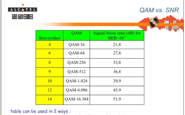
Bits/symbol QAM Signal/Noise ratio (dB) forBER<10-7
4 QAM-16 21,8 6 QAM-64 27,8 8 QAM-256 33,8 9 QAM-512 36,8 10 QAM-1.024 39,9 12 QAM-4.096 45,9 14 QAM-16.384 51,9
QAM vs. SNR
table can be used in 2 ways :
(a) what is minimum required SNR to modulate N bits on a carrier (b) how many bits can be modulated given a SNR of Y dB
© 2001, Alcatel Bell N.V. All rights reserved
Alcatel University Antwerp, page n° 32
Discrete Multi Tone (DMT)
For ADSL multiple carrier frequencies are modulated on the 1
ADSL line using Quadrature Amplitude Modulation.
These frequencies are equally spaced and for each carrier the
SNR is measured to determine the maximum achievable QAM.
The sum of all frequencies is put on the line This principle is called Discrete Multi Tone (DMT)
770 00905 0370-VHBE_Ed_08 33 © 2001 Alcatel Bell N.V., All rights reserved © 2001, Alcatel Bell N.V. All rights reserved
Alcatel University Antwerp, page n° 33
Ts (Symbol Time)
Discrete Multi Tone example
QAM-4 1
QAM-16 2
QAM-4 3
Σ
= DMT1 DMT Symbol
Imagine a certain frequency spectrum that is divided in 3 subchannels. To every of these 3 subchannels we can assign an appropriate QAM scheme depending on the measured SNR. The sum of these QAM signals is made and then sent to an DAC (Digital Analogue Convertor). The outcome is an analogue signal that is put on the transmission line.
Dividing the frequency spectrum in subchannels can be done in different ways.
Or we can consider only a few subchannels but then we loose the flexibility of assigning different amount of data bits to relatively small fractions of the frequency spectrum; or we could consider an enormous amount of subchannels. This results in increased complexity.
© 2001, Alcatel Bell N.V. All rights reserved
Alcatel University Antwerp, page n° 34
DMT and ADSL
The spectrum used for ADSL is divided into 255 carriers.
¾ Each carrier is situated at n x 4,3125 kHz
For the upstream direction carriers 7 to 29 are used For the downstream direction carriers 38 to 255 are used On each carrier the SNR is measured and the QAM determined.
¾ Minimum ÖQAM-4 Ö2bits/symbol ¾ Maximum ÖQAM- 16384 Ö14 bits/symbol
770 00905 0370-VHBE_Ed_08 35 © 2001 Alcatel Bell N.V., All rights reserved © 2001, Alcatel Bell N.V. All rights reserved
Alcatel University Antwerp, page n° 35
DMT vs. line characteristics
7 29 38 255 4 30 125 165 1100 • • • • • • Frequency interference frequency attenuation Bits / carrier carrier frequency (kHz) ADSL filter characteristics Line characteristicsSince the attenuation increases with the frequency (skin effect) the SNR drops with increasing frequencies.
Thus less bits/carrier can be assigned for the upper subchannels.
This explains why it is useless to consider frequencies above 1.1 MHz.
Considering frequencies above 1.1 MHz is done in VHDSL (Very High Speed DSL). Since we have to compensate for the skin effect, in this application the distance has to be limited.
What about Discrete Multitone (DMT)?
Dividing the used frequency spectrum in subchannels results in the possibility to assign a different QAM scheme on every subchannel. So depending on the SNR of a specific carrier, more or less data bits can be transported.
© 2001, Alcatel Bell N.V. All rights reserved
Alcatel University Antwerp, page n° 36 Bits/carrier Carriers 2 3 4 5 6 7 8 9 10 11 12 13 14
Maximum value after SNR measurement per carrier at startup Possible working value at startup
1
# bits / carrier
We will always assign less bits to the carriers then allowed by the measured SNR. Typically we assign an average of 2 bits less.
This margin is called the Target Noise Margin and is configurable via the AWS. You specify what the average margin should be right after startup in dB. The modem measures the available SNR, then subtracts the Target Noise Margin, and then checks to what constellation it would fit. By default the TNM is 6 dB.
Why?
In case of a disturbance (e.g. RFI), we do not want our overall speed to drop. Whenever a subchannel becomes unavailable to transport data bits the spare bits in adjacent subchannels will be used. (see next slides)
770 00905 0370-VHBE_Ed_08 37 © 2001 Alcatel Bell N.V., All rights reserved © 2001, Alcatel Bell N.V. All rights reserved
Alcatel University Antwerp, page n° 37
Bitswapping
After startup we will use a lower QAM then possible on most of
the carriers.
¾ The measured SNR at startup determines the maximum possible
QAM at startup, e.g.: QAM-4096 corresponding to 12bits/symbol >>> used QAM on that carrier: QAM-1024 (10bits/symbol)
¾ This results in extra bits that could be allocated on that carrier.
During showtime (modem operation) the SNR is measured on all
carriers at regular intervals (default 1sec).
¾ If the SNR on a certain carrier degrades resulting at a lower QAM
that can be used on that carrier, the bits of that carrier will be re-allocated to other carriers where the max QAM is higher then the actual used QAM.
¾ The modems will try to spread out the re-allocated bits over
numerous carriers.
It is not fully correct to speak about QAM constellations and bits here. It should be noise margins. The rule is : the ATU tries to equalise the noise margin over all tones, what could lead to bits being moved from one tone to another, and even tones to disappear or to appear. Margins are "analog" where bits are "digital". As you need 3 dB for 1 bit, a margin of 4.7 dB over all tones can not be translated into bits.
Modem does not calculate with bits. It measures the available SNR, then subtracts the Target Noise Margin, and then checks to what constellation it would fit (table slide 31). There is also the possibility to increase (or decrease) the gain of each tone (+ -2.5 dB, but sum over all tones must be 0) for those tones which have just a little bit shortage to have 1 bit more loaded. A gain change results directly in signal change, so also SNR change.
© 2001, Alcatel Bell N.V. All rights reserved
Alcatel University Antwerp, page n° 38
Bitswapping explained
Bits/carrier Carriers 2 3 4 5 6 7 8 9 10 11 12 13 14 1Sudden frequency interference decreases SNR on a number of carriers
Current max. bits/carrier
770 00905 0370-VHBE_Ed_08 39 © 2001 Alcatel Bell N.V., All rights reserved © 2001, Alcatel Bell N.V. All rights reserved
Alcatel University Antwerp, page n° 39
Bitswapping explained
Bits/carrier Carriers 2 3 4 5 6 7 8 9 10 11 12 13 14 1A lower SNR also lowers our max QAM (the number of bits on those carriers)
Current max. bits/carrier
Current used bits/carrier
© 2001, Alcatel Bell N.V. All rights reserved
Alcatel University Antwerp, page n° 40
Bitswapping explained
Bits/carrier Carriers 2 3 4 5 6 7 8 9 10 11 12 13 14 1Current max. bits/carrier
770 00905 0370-VHBE_Ed_08 41 © 2001 Alcatel Bell N.V., All rights reserved © 2001, Alcatel Bell N.V. All rights reserved
Alcatel University Antwerp, page n° 41
Bitswapping explained
Bits/carrier Carriers 2 3 4 5 6 7 8 9 10 11 12 13 14 1Current max. bits/carrier
Current used bits/carrier Noise margin is spread over the full spectrum
© 2001, Alcatel Bell N.V. All rights reserved
Alcatel University Antwerp, page n° 42
DOWN modulation UP demodulation ADLT DMT FRAME (ATU-C)
U
nshielded Twisted PairDOWN demodulation UP modulation ADNT DMT FRAME (ATU-R)
2 analogue signals (UP,DOWN) travelling in opposite directions over the UTP
Communicating modems
ATU-R locks to the pilot carrier in the downstream direction (PLL)
¾ The better the lock the better the overall SNR!
Modems using the ANSI ADSL standard locks to a carrier in the up - and downstream direction, i.e. the ATU-R locks to the pilot (carrier 63) in the downstream part and the ATU-C locks to the pilot in the upstream part. ANSI has 2 pilot carriers, 1 in the downstream and 1 in the upstream.
Modems using the ITU-T ADSL standards only require the ATU-R to lock to the ATU-C and also use this lock for his upstream transmission.
770 00905 0370-VHBE_Ed_08 43 © 2001 Alcatel Bell N.V., All rights reserved © 2001, Alcatel Bell N.V. All rights reserved
Alcatel University Antwerp, page n° 43
ADSL Superframe
DMT Symbol:
¾ a DMT symbol is the sum of all symbols on each individual carrier.
Data Symbol (DS):
¾ a data symbol is used to transmit information (data).
Synchronisation Symbol (SS):
¾ a sync symbol is transmit after 68 data symbols to assure
synchronisation and to detect a possible loss of frame. ADSL symbol period:
¾ Ts = 17 ms / 69 = 246,377 µs
¾ Ts = 17 ms / 68 = 250 µs (symbol period for the data plane!)
DS 3 DS 2 DS 1 DS 4 . . . . . DS 67 DS 68 SS 69 SUPERFRAME 17 ms DMT Symbol
© 2001, Alcatel Bell N.V. All rights reserved
Error detection and correction
Error detection and correction
770 00905 0370-VHBE_Ed_08 45 © 2001 Alcatel Bell N.V., All rights reserved © 2001, Alcatel Bell N.V. All rights reserved
Alcatel University Antwerp, page n° 45
Error detection & correction principle
DISTANCE = 2 t + 1
Correction Mode Detection Mode
1 bit error 2 bit error 3 bit error 2 bit error 1 bit error
= Valid data = Invalid data
•2 bit error correction (t=2)
•3 bit error detection (d=3)
•More than 3 bit error results in wrong correction
•5 bit error detection (d=5)
ERROR CORRECTION/DETECTION PRINCIPLE
Imagine that the green spots on the slide represent a bitsequence that is used to transmit data. If during the transport bit errors occur (single or multiple) they will result in one of the red invalid bitsequences. At
that moment the receiver can execute bit error correction by locating the nearest green spot (see
example above). In this way it is possible to correct up to 2 bit errors.
If a 3 bit error occurs, it cannot be corrected because then the distance to the green spots (left and right) is
equal. In this case only an error detectionis possible. Even worse, when more than 3 bit errors occur, it
is possible that the other side receives a “red” bitsequence that is closer to another green spot. In this
case a wrong correctionis executed and the error correction code fails.
The error correction possibility can be calculated as follows: - DISTANCE between the green spots = 6 = 2 t + 1
- Number of errors than can be corrected = t = 2
The distance between the valid data sequences can be increased by adding check bytes to the original data (see Reed Solomon, Trellis, …)
ERROR DETECTION PRINCIPLE
In the previous example a 3 bit error was the maximum allowed. More than 3 bit errors will result in wrong corrections. It is possible to increase the number of bit errors that can be detected in a simple way. If both sides agree not to execute error corrections, up to 5 bit errors can be detected (because the distance
is 6). In other words, all red spots will result in an error detection. The disadvantage is that there is no
error correction possible.
EXAMPLES
•ADSL (Reed Solomon and Trellis) always works in correction mode
• ATM (HEC code) uses correction mode and will temporary switch to detection mode when errors occur.
© 2001, Alcatel Bell N.V. All rights reserved
Alcatel University Antwerp, page n° 46
Error detection & correction
The choise of correction mode or detection mode is a consensus!
¾ Will you choose the ability to detect AND correct errors with
the possibility you introduce more errors,
¾ Or will you choose the ability to detect a higher number of errors
with no possibility to correct them but at least you not introduce more errors.
Some coding mechanisms will switch from correction mode to
detection mode as soon as errors are detected! (e.g. ATM) ¾ This is done done as errors are mostly of a bursty nature and
770 00905 0370-VHBE_Ed_08 47 © 2001 Alcatel Bell N.V., All rights reserved © 2001, Alcatel Bell N.V. All rights reserved
Alcatel University Antwerp, page n° 47 Byte 1 2 3 4 239 k byte message vector n byte code vector 254 255 240 n - k check bytes Code RS(255,239) Distance: n-k+1 d= 255-239+1 d=17 Correction: (d-1)/2 c=(17-1)/2 c = 8
With 16 check bytes, the RS code can correct up to 8 erroneous bytes
per code vector Error correction overhead = 16/255 = 6.3 %
Reed Solomon (correction mode)
Because of the presence of impulsive noise (infrequent high amplitude bursts of noice mostly caused by central office switching transients, dial pulses, POTS ringing, neighboring railway stations, elevators,…that can corrupt the signal beyond recognition) on the twisted pair wire means must be implemented to make sure that the ADSL transceiver is sufficiently robust against this impulsive noise and to maintain an acceptable BER for good quality of services.
© 2001, Alcatel Bell N.V. All rights reserved
Alcatel University Antwerp, page n° 48
Message vector Ctrl Received data Transmitted data Distance = 15-11+1= 5 Correction = (5-1)/2= 2 More then 2 lost bytes Burst of errors Data to be transmitted
Reed Solomon
Lost data770 00905 0370-VHBE_Ed_08 49 © 2001 Alcatel Bell N.V., All rights reserved © 2001, Alcatel Bell N.V. All rights reserved
Alcatel University Antwerp, page n° 49
Interleaving
Message
vector Ctrl Data to be transmitted
Transmitted Data
Bloc 0 Bloc 1 Bloc 2
Received Data Ctrl
Correction Correction CtrlCorrection CtrlCorrection CtrlCorrection Ctrl
Bloc 3 Bloc 4
Bloc 0 Bloc 1 Bloc 2 Bloc 3
Burst errors
6 lost bytes
1 Byte error per bloc!
Interleaving:
In stead of transmitting our RS code words directly on the line we will create a frame of the same size made up by multiple RS words by taking only a portion of each of the original RS words. This has the advantage when a burst of errors occur on the line and the original RS words are recreated on the receiving side, the errors will be spread over multiple RS words. This could mean that we are able to correct the errors within a single RS word if the number of errors are within the RS correction boundaries.
Interleaving depths:
The main disadvantage of interleaving is the high delay. Constructing the blocs that will finally be transmitted over the line take time as you have to wait for a time before you can actually start transmitting. In our example here we need 15 original RS words (1 Byte of each) before we can construct the first block that is actually transmitted over the line.
At the receiving side it will also cost extra time to reconstruct the original RS word. The first original RS word can not be reconstructed before we have received all the bytes of this first RS word.
Interleaving can be sped up by using different depths, i.e. by taking bigger chunks of the original RS words you will be able to construct your first bloc for transmission much quicker. This has the disadvantage that errors will be spread over less RS words on the receiving side with the possibility that they can not be corrected.
Alcatel introduces 3 interleaving depths: high, medium andlow.
Where high uses the smallest portions to construct a frame for transmission, consequently the high interleaving depth will introduce the highest delay as this one will need more frames to construct/reconstruct before transmission/reception.
© 2001, Alcatel Bell N.V. All rights reserved
Alcatel University Antwerp, page n° 50
Reed Solomon ATM burst
RS has the characteristic of generating bursty ATM traffic
¾ The result might be that a policing function discards ATM cells
Therefore we need to shape the ATM traffic
¾ ATM cells will be transmitted at line rate
ATM cell: 53 Bytes
RS Decoder
+ Buffer Burst of 4 ATM cells functionsATM
Reed Solomon overhead 1B
Reed Solomon words coming from lower levels
Max. 4 complete ATM cells
Traffic shaper
770 00905 0370-VHBE_Ed_08 51 © 2001 Alcatel Bell N.V., All rights reserved © 2001, Alcatel Bell N.V. All rights reserved
Alcatel University Antwerp, page n° 51
Delay & interleaving depths
FAST = NO INTERLEAVING !
© 2001, Alcatel Bell N.V. All rights reserved
Alcatel University Antwerp, page n° 52
Trellis coding
Trellis coding is another error detection and correction
mechanism which is optional for ADSL.
Trellis principle =>
¾ looking at the complete data you’re able to detect and correct
errors, analogue to detection and correction in spoken language
¾ example:
transmitted data: the water is wet and cold received data: the water is let and cold
¾ By just looking at the word letwe can not know that it is wrong! ¾ By looking at the information before and after the word we can
safely say that it should be wetinstead of let.
Trellis will also add extra information (overhead) to the transmitted data in order to perform his detection and correction.
This overhead is apc. 1/2 bit per used carrier + 4 bits.
A Viterbi coder/decoder will look at the received data and calculate what the most logical value should be for the received data similar to spoken language as illustrated on the slide.
770 00905 0370-VHBE_Ed_08 53 © 2001 Alcatel Bell N.V., All rights reserved © 2001, Alcatel Bell N.V. All rights reserved
Alcatel University Antwerp, page n° 53
ADSL & Reed Solomon
DS 3 DS 2 DS 1 DS 4 . . . . . DS 67 DS 68 SS 69 SUPERFRAME 17 ms DMT Symbol
Assume Trellis coding is not used!!
1 Data symbol corresponds to a 255Byte Reed Solomon word. Some bytes in the RS word are framing overhead used for
modem to modem communication (EOC, AOC, IB, CRC).
If RS is not used our data still runs through the RS coder! The maximum downstream ADSL speed for our data :
¾ with Reed Solomon:
(255-16-1) x 8bits/byte x 4000 symb/sec = 7,616 Mbits/sec
¾ without Reed Solomon:
(255-1) x 8bits/byte x 4000 symb/sec = 8,128 Mbits/sec
With Trellis used; extra bytes will be needed in the DMT symbol.
For fast (no interleaving) there is exactly one RS word in one DMT symbol. Reed Solomon always performs his calculation on a word of 255 Bytes which is also the maximum length. Our user data (ATM cells) always run through this Reed Solomon coder giving you the maximum speeds as calculated on the slide.
Some payload Bytes of the RS word are used for maintenance communication. Over these Bytes, which are negotiated at start-up, following information can be transmitted
1) EOC: Embedded Operations channel
Is intended to exchange physical layer messages between the ATU–C and the ATU–R. For example what the SNRs are, or what the output power is of the transmitter, ... 2) AOC: ADSL Overhead Control channel
The ADSL Overhead Channel is intended for bit swap operations 3) CRC: Cyclic Redundancy Check
The transmitter shall calculate a CRC over the data of last superframe, and send this CRC to the receiver. The receiver also calculates the CRC over the same data block, and compare it to the received CRC value. When those do not correspond, a CRC error event shall be generated.
4) IB: Indicator Bits
They indicate a number of states and alarms like CRC errors, loss of signal, loss of frame, etc. 5) Dummy information
© 2001, Alcatel Bell N.V. All rights reserved
Alcatel University Antwerp, page n° 54
Coding gain
From the table on slide 31we have seen that to attain a BER of
10-7for a specific QAM you need a certain SNR.
¾ If the SNR is lower then this value the BER becomes to high ¾ By introducing error detection and correction you lower the BER
because you correct a number of the introduced errors. The mechanism introduces a coding gain resulting in an actual
lower SNR that is needed to achieve a certain constellation. ¾ Trellis introduces a coding gain of apc. 5,5dB.
¾ Reed Solomon introduces a coding gain of apc. 4dB. ¾ Trellis & RS together introduce a coding gain of apc. 9dB.
Bits/symbol QAM uncoded Trellis RS Trellis + RS
4 QAM-16 21,5 16 17,5 12,5
6 QAM-64 27,5 22 23,5 18,5
SNR for BER = 1E-7
The numbers given a relative and not exact. In ADSL implementations the numbers will differ a bit depending on the QAM desired and the product manufacturer.
770 00905 0370-VHBE_Ed_08 55 © 2001 Alcatel Bell N.V., All rights reserved © 2001, Alcatel Bell N.V. All rights reserved
Alcatel University Antwerp, page n° 55
ADSL rates
ATM attainable rate
¾ Maximum possible ATM rate
ATM used rate
¾ Currently used ATM rate
Used line rate
¾ actual ADSL line rate
Attainable line rate
¾ Maximum attainable line rate based on SNR measurement
Trellis overhead Attainable
line rate ATM data Reed Solomon overhead Framing overhead
1 up to 6 Bytes
Max. 255 Bytes 1/2bit per carrier
+ 4 bits
1B
Relative Capacity Occupation (RCO in%): proportion of the used line rate to the attainable line rate
Reed Solomon has to be supported by the ADSL modems according to the standardisation. This does not mean that Reed Solomon must be activated at all times.
Trellis on the other hand is optional!
During start-up of the ADSL modems capabilities are transferred between the modems and based on this the ATU-C (in the ASAM) decides what is used. Also during this phase it is communicated how many bytes are used in the framing overhead, this is mostly only 1Byte to have the most optimal performance. Example for downstream: (taken from ADSL diagnostics)
ATM attainable rate: 8,128 Mbps [(255-1) x 4000 x 8]
ATM used rate: 8,128 Mbps
Used line rate: 8,612 Mbps
Attainable line rate: 10,236 Mbps
RCO: 84% [(8,612 / 10,236) x 100]
Short haul local loop with Reed Solomon disabled (used ATM rate = attainable ATM rate) and Trellis activated (Used line rate >> {ATM used rate + modem-modem communication overhead}). And there’s 1 Byte of framing overhead.
© 2001, Alcatel Bell N.V. All rights reserved
xDSL Technologies
xDSL Technologies
770 00905 0370-VHBE_Ed_08 57 © 2001 Alcatel Bell N.V., All rights reserved © 2001, Alcatel Bell N.V. All rights reserved
Alcatel University Antwerp, page n° 57
Symmetrical DSL technologies
Over the years many different symmetrical DSL types have been defined by different standardisation bodies. Where to place these different types, with which speed, over the years you can see on the slide. Most of them are designed for a set fixed speed indicated by the small squares. Only SDSL and SHDSL are rate adaptive, meaning that the supported speed varies from a minimum to a maximum speed. Depending on the line quality a certain speed can be attained.
© 2001, Alcatel Bell N.V. All rights reserved
Alcatel University Antwerp, page n° 58
Symmetrical DSL comparison
Comparison of a few symmetrical DSL technologies. The differences are mainly in the used type of modulation and if it is rate-adaptive or not.
With power backoff we mean the possibility to lower the nominal output power of the transmitter and as such possibly lower the crosstalk.
770 00905 0370-VHBE_Ed_08 59 © 2001 Alcatel Bell N.V., All rights reserved © 2001, Alcatel Bell N.V. All rights reserved
Alcatel University Antwerp, page n° 59
SHDSL
Single-pair High speed DSL!
¾ ITU-T G991.2 specification (waiting for approval) ¾ ETSI TS 101 524 -1 & -2 v1.1.1
¾ Full duplex and used with 1 or 2 pairs
¾ Trellis Coded Pulse Amplitude Modulation (TC PAM) with 16 levels
Designed to be spectral compatible with adsl in the same bundle Rate adaptive
¾ Symmetrical data rate from 192kbps to 2312 kbps for 1 pair!
Maximum range up to 2,5 km without repeaters
Symmetrical PSD mask or assymmetrical PSD mask (North-America)
SHDSL is defined by the ITU-T as Single-pair High speed DSL and is designed primarily for duplex operation over two-wire twisted metallic pairs. Optional four-wire operation is supported for extended
reach applications. SHDSL transceivers are capable of supporting selected symmetrical user data rates
in the range of 192 kbps to 2.312 kbps using a Trellis Coded Pulse Amplitude Modulation (TC-PAM) line code. They are designed to be spectrally compatible with other transmission technologies deployed in the access network, including other DSL technologies. SHDSL transceivers do not support the use of analogue splitting technology for coexistence with either POTS or ISDN.
Symmetrical and assymetrical PSD masks are defined but only the symmetrical PSD masks are mandatory. The assymetrical PSD masks are optional and are for the North American market. Currently 2 assymmetrical PSD masks have been defined for following datarates:
1) 768 kbps or 776 kbps 2) 1536 kbps or 1544 kbps.
The exact meaning of PSD is explained further in the presentation!
SHDSL
modem SHDSL modem
Local exchange Remote user
Local line
STU-C
orSHLT
STU-R
© 2001, Alcatel Bell N.V. All rights reserved
Alcatel University Antwerp, page n° 60
SHDSL functional
PRECODER
SCRAMBLER ENCODERTRELLIS DAC DRIVERLINE FRAMER PAYLOAD DATA • Randomizes the signal • Avoids periodic signals • Maps 3 bits in one symbol • calculates coding bit •Adds coding bit to the symbol • forms the symbol • introduces predistortion • compensates the line distortion • Digital to analog conversion • Amplifies signal • Drives the line • Maps payload
to SHDSL frame • Inserts EOC
Any SHDSL modem has these main functions. The user data is mapped into the SHDSL frame (explained on next slide) after which the frame is modulated using TC-PAM 4. TC-PAM 4 means that in each symbol we can put 4 bits, meaning there are 16 different distinctive levels. Of the SHDSL frame we take 3 bits to put into the symbol the fourth bit in the symbol is used by the trellis coder to put his coding bit (Trellis overhead).
We can say that the Trellis encoder adds a coding bit every 3 bits in the SHDSL frame and then we take these 4 bits to create the corresponding symbol and put it on the line.
770 00905 0370-VHBE_Ed_08 61 © 2001 Alcatel Bell N.V., All rights reserved © 2001, Alcatel Bell N.V. All rights reserved
Alcatel University Antwerp, page n° 61
SHDSL frame structure
Payload rate = n x 64kbps + i x 8kbps [192kbps Ö2,312Mbps] ¾ 3 ≤n ≤36 and 0 ≤i ≤7 K = 12 [i + (n x 8)] bits PAYLOAD BLOCK #1 PAYLOAD BLOCK #2 PAYLOAD BLOCK #3 PAYLOAD BLOCK #4 FRAME SYNC O H O H O H O H 14 2 k 10 k 10 k 10 k 2 2 6 ms Su b bl ock 1 Su b bl ock 2 Su b bl ock 3 Su b bl ock 4 Su b bl ock 5 Su b bl ock 6 Su b bl ock 7 Su b bl ock 8 Su b bl ock 9 Su b bl ock 10 Su b bl ock 11 Su b bl ock 12 ks FRAME SYNC : 11111100001100 OH : OVERHEAD, total of 32 bitsStuffing (0 or 4) or spare bits (2)
The payload rate is requested by the user and is determined by the formula mentioned on the slide. When n = 36 the value for i is limited to 0 or 1.
With current implementations for transport of ATM cells (like in ADSL) the value of i is limited to 0!
The transmission of the last 4 stuffing/spare bits is determined by the transmission mode, either we transmit 0, 2 or 4 of these bits. In case of 2 bits, with synchronous transmission mode (explained on next slide) these are spare bits and the exact length of a SHDSL frame is 6ms.
Within a SHDSL frame we find a frame sync word used for frame synchronisation, overhead bits (usage explained on next slide), 4 payload blocks of a size K and up to 4 extra bits depending on the transmission mode.
The size of each payload block is also determined by the parameters n and i, and so in relation with the requested user data rate.
The higher the requested user rate the longer a SHDSL frame will be. We can clearly see with this that for a higher user rate we need a higher symbol rate because of the longer SHDSL frame.
© 2001, Alcatel Bell N.V. All rights reserved
Alcatel University Antwerp, page n° 62
SHDSL modes
Plesiochronous mode:
¾ No stuffing bits at end of frame
SHDSL frame Tx in 6ms – ( 2 x 6 / #bits in frame) ms
¾ 4 stuffing bits at end of frame
SHDSL frame Tx in 6ms + ( 2 x 6 / #bits in frame) ms Synchronous mode:
¾ No stuffing bits only 2 spare bits at end of SHDSL frame
SHDSL frame Tx in 6 ms
Plesiochronous mode uses a clocking scheme in which the SHDSL frame is based on the input transmit clock but the symbol clock is based on another independent clock source.
Synchronous mode uses a clocking scheme in which the SHDSL frame andthe symbol clock are based
on the STU-C input transmit clock or a related network timing source. Synchronous mode is mainly used by the current implementations.
770 00905 0370-VHBE_Ed_08 63 © 2001 Alcatel Bell N.V., All rights reserved © 2001, Alcatel Bell N.V. All rights reserved
Alcatel University Antwerp, page n° 63
SHDSL overhead bits
The overhead bits (OH) in the SHDSL frame transport: Embedded Operations Channel (EOC): 20 bits
¾ Transports maintenance messages over HDLC protocol
Cyclic Redundancy Check (CRC-6): 6 bits
¾ CRC over transmitted SHDSL frame
Indicator Bits (IB): 4 bits
¾ To report loss of signal, segment anomaly, power loss & loss of sync
Stuffing indicator bits: 2 bits
¾ Only used in plesiochronous mode (spare in synchronous mode) ¾ Indicate presence of stuffing bits at the end of SHDSLframe
© 2001, Alcatel Bell N.V. All rights reserved
Alcatel University Antwerp, page n° 64
SHDSL rates calculation
SHDSL frame length = 14 + 32 + 2 + (4 x K) bits
[= sync word + OH + spare + ( 4 x Payload blocks K)]
K = 12 (8n + i) bits
Datarate R = 64n + 8i kbps
Frame is Tx in 6 ms, from this we calculate the symbol period (Ts)
¾ With 3 bits per symbol each symbol takes
Ts = 6ms / (frame length/3) = 6ms x 3 / [48 + (4 x 12 x (8n+i))]
¾ # symbols / second = 1/symbol period = Rs = 1/Ts
= [48 + (4 x 12 (8n+i))] / 6 x 3
= [8 + (8 x (8n+i))] / 3 = (8 + 64n + 8i) / 3
= (8 + R) / 3 ksymbols/sec
770 00905 0370-VHBE_Ed_08 65 © 2001 Alcatel Bell N.V., All rights reserved © 2001, Alcatel Bell N.V. All rights reserved
Alcatel University Antwerp, page n° 65
Spectral compatibility
PSD is a representation of the associated energy for a certain frequency It indicates the potential for generating noise towards other cables in
the same bundle for those frequencies!
Data rate = 768 kbps
Rs SHDSL = 258,666 ksymb/sec
As said on the the slide the power spectral density (PSD) is a good representation of the associated energy that a specific type of modulation has within a certain frequency band.
This PSD gives us a good indication for what frequencies there’s a stronger radiation. This is especially important for field implementations where we have cable bundles and where we should limit the radiation from one cable to the other and as such the crosstalk.
SHDSL is a rate adaptive technology using TC-PAM which means that for higher data rates the used frequency band is also higher. (symbol rate is higher!) We can see on the slide that for a datarate of 768kbps the PSD affects mostly the frequencies up to 300kHz and thus interfering with the upstream band of ADSL. In order to limit the crosstalk the different standard organisations have specified PSD masks for the different possible datarates. For a specific datarate the PSD has to stay within his mask. Upto now two types have been defined: symmetrical PSD masks and assymmetrical PSD masks which is mainly used for North American implementations and only for a few distinctive set rates.
The symmetrical PSD masks have to be supported by all SHDSL modems, where the assymmetrical PSD mask are optional.
This drawing represents the symmetrical PSD masks defined by the ITU-T for the datarates mentioned.
© 2001, Alcatel Bell N.V. All rights reserved
Alcatel University Antwerp, page n° 66
VDSL
Very high bitrate Digital Subscriber Line Assymetric service providing:
¾ Upto apc. 52Mbps in the downstream direction ¾ Upto apc. 16Mbps in the upstream direction
Uses frequencies upto 30MHz
Distance limited to a few 100 meters
770 00905 0370-VHBE_Ed_08 67 © 2001 Alcatel Bell N.V., All rights reserved © 2001, Alcatel Bell N.V. All rights reserved
Alcatel University Antwerp, page n° 67
Which DSL to choose
Residential customers
•Single phone line
•Internet access
Business customers
•Multiple phone lines •Network access