www.radar-electronics.com
e-mail.:[email protected]
PreView
®
Display
CD6102 / CD6102 OC /
CD6102-2
Operating Manual
Contents
Operator Display Description
...
1
Display Unit Function
...
2
Mounting Instructions
...
2
Troubleshooting
...
3
Specifications
...
4
Warranty Information
...
5
PATENTS
Patented under one or more of the following U.S. Patents:
5345471, 5523760, 5457394, 5465094, 5512834, 5521600, 5682164, 5630216, 5510800, 5661490, 5609059, 5774091, 5757320, 5581256, 5832772, 5519400, 5767953, 5767627, 5589838, 5563605, 5661385, 5517198, 5610611, 5883591, 5805110, 5754144, 7088284, and 7215278.
Other patents have been applied for. TRADEMARKS
The names of actual companies and products mentioned herein may be the trademarks of their respective owners. Any rights not expressly granted herein are reserved.
Tel: +386 3 4900 800 http://radar-electronics.com/ 3700046C Copyright 2016 Page 1
Operator Display Description
CD6102–
the CD6102 operator display family is a Common Display used
with all the PreView® CAN based sensors. This display provides the vehicle
operator with a visual indication of a detected object. The display unit also
contains a buzzer to provide an audible alert that will increase in rate as an
object becomes closer, providing the operator with another cue that an
object is being detected.
A switch is provided on the front panel of the display allowing the vehicle
operator the ability to adjust the buzzer volume to three different levels or to
provide an alarm acknowledge and silence the buzzer.
CD6102-2 –
is a CD6102 display factory configured for a two sensor
PreView® system.
CD6102 OC –
is a CD6102 display sealed for an open cab application.
This display does not contain a switch to adjust the volume.
The operator display continuously monitors communication from the
PreView® sensor and in the event of a system failure or malfunction, will
notify the operator with a fault indication.
The PreView
®system is a blind spot collision warning system
designed to supplement other safety practices and/or devices.
The machine operator is always the first line of defense when
safely operating a vehicle.
Tel: +386 3 4900 800 http://radar-electronics.com/ 3700046C Copyright 2016 Page 2
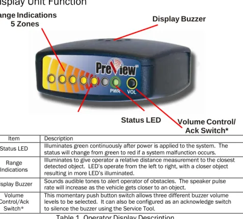
Display Unit Function
Range Indications
5 Zones
Display Buzzer
Status LED
Volume Control/
Ack Switch*
Item Description
Status LED Illuminates green continuously after power is applied to the system. The
status will change from green to red if a system malfunction occurs. Range
Indications
Illuminates to give operator a relative distance measurement to the closest detected object. LED’s operate from the left to right, with a closer object resulting in more LED’s illuminated.
Display Buzzer Sounds audible tones to alert operator of obstacles. The speaker pulse rate will increase as the vehicle gets closer to an object. Volume
Control/Ack Switch*
This momentary push button switch allows three different buzzer volume levels to be selected. It can also be configured as an acknowledge switch to silence the buzzer using the Service Tool.
Table 1. Operator Display Description
*CD6102 OC display does not contain a Volume Control / Ack Switch
Mounting Instructions
Display Unit Installation
The display unit should be mounted where the vehicle operator can easily
view it while backing. The ideal location for this is on the dash positioned by
either windshield pillar. This will allow the operator view of the display while
also looking out one of the side mirrors.
The PreView® display unit comes equipped with a mounting bracket and
hardware. If desired, the display unit can be mounted to the display bracket
with the supplied hardware. This bracket can then be mounted in the
vehicle cab as desired.
The display receives power from the sensor. See installation guide and
supplied manuals for more information.
Tel: +386 3 4900 800 http://radar-electronics.com/ 3700046C Copyright 2016 Page 3
Troubleshooting
Display Status LED is not illuminated.
Verify that DC power (9-33V) is applied to the sensor.
Verify that the cable between the sensor and display is connected.
Display Status LED is RED.
Check connection between display and sensor.
Display Status LED is RED and one Yellow LED is illuminated.
LED Error Code Possible Reason
LED #5 on No communication with any sensor(s)
LED #4 on Built in Self Test Error – Contact Factory
LED #3 on Missing sensor(s)
All 5 Yellow LEDs on Blockage Error*
All the display LED’s are illuminated when sensor is mounted.
Verify the sensor is pointing outward from the vehicle in an open
area with no obstructions. This may require removing the mounting
screws and lifting the sensor out away from the rear of the vehicle.
If the display LED’s are not active when moved away from the
vehicle, but are active when mounted, then the sensors mounting
position will have to be moved.
Sensor is detecting the ground, indicated by a few of the display LED’s
being lit.
In an open field, either move the sensor up higher or slightly angle
the sensor upward 5 to 10 degrees. The minimum recommended
mounting height is 24 inches.
*Blockage Error only reported by Sentry sensors.
For questions, call +1.844.787.2327 toll free in the USA. Call
+1.208.323.1000 or send a fax request to +1.208.323.1034 for outside
the USA, or submit an online request at www.preco.com/contact-us/
Tel: +386 3 4900 800 http://radar-electronics.com/ 3700046C Copyright 2016 Page 4
Specifications
DISPLAY SPECIFICATIONS (Typical)
Housing Material: Polycarbonate/ABS alloy
Dimensions: 1.00”H x 2.25"W x 2.00"D (2.5cm x 5.7cm x 5.1cm) Weight: 0.25 lb. (0.11 kg)
Mounting: User dependent ELECTRICAL SPECIFICATIONS
Power supplied by sensor OPERATING CHARACTERISTICS Warning Ranges: 5 zones COMMUNICATION
Physical Layer: CAN 2.0B, 250 KB/s Protocol Layer: SAE J1939 Extended Data Update Rate: 70 ms
8
MATING END VIEW
PRODUCT MANUFACTURED IN THE USA
7
CONNECTOR PIN OUT
PIN
SIGNAL NAME
1
CAN HIGH
2
CAN LOW
3
-
4
-
5
POWER
6
GROUND
7
-
8
-
Tel: +386 3 4900 800 http://radar-electronics.com/ 3700046C Copyright 2016 Page 5
Warranty Information
MANUFACTURER STANDARD LIMITED WARRANTY AND LIMITATION OF LIABILITY
Manufacturer warrants that on the Date of Purchase this Product will conform to Manufacturer's published specifications for the product, which are available from Manufacturer on request, and Manufacturer warrants that the product is free from defects in materials and workmanship. This Limited Warranty for the Display extends for sixty (60) months from the date of shipment. Manufacturer will, at its option, repair or replace any product found by Manufacturer to be defective and subject to this Limited Warranty.
This Limited Warranty does not apply to parts or products that are misused; abused; modified; damaged by accident, fire or other hazard; improperly installed or operated; or not maintained in accordance with the maintenance procedures set forth in Manufacturer's Installation and Operating Instructions.
To obtain warranty service, you must ship the product(s) to the specified Manufacturer location within thirty (30) days from expiration of the warranty period. To obtain warranty service you must call Customer Service at 866-977-7236 or 323-1000, or fax your request to 208-323-1034. Customer Service will issue warranty authorization and further instructions. You must prepay shipping charges and use the original shipping container or equivalent.
EXCLUSION OF OTHER WARRANTIES: MANUFACTURER MAKES NO OTHER WARRANTIES, EXPRESSED, IMPLIED OR STATUTORY. THE IMPLIED WARRANTIES FOR MERCHANTABILITY AND FITNESS FOR A PARTICULAR PURPOSE ARE HEREBY EXCLUDED AND SHALL NOT APPLY TO THE PRODUCT. BUYER'S SOLE AND EXCLUSIVE REMEDY IN CONTRACT, TORT OR UNDER ANY OTHER THEORY AGAINST MANUFACTURER RESPECTING THE PRODUCT AND ITS USE SHALL BE THE REPLACEMENT OR REPAIR OF THE PRODUCT AS DESCRIBED ABOVE.
LIMITATION OF LIABILITY: IN THE EVENT OF LIABILITY FOR DAMAGES ARISING OUT OF THIS LIMITED WARRANTY OR ANY OTHER CLAIM RELATED TO MANUFACTURER'S PRODUCTS, MANUFACTURER'S LIABILITY FOR DAMAGES SHALL BE LIMITED TO THE AMOUNT PAID FOR THE PRODUCT AT THE TIME OF ORIGINAL PURCHASE. IN NO EVENT SHALL MANUFACTURER BE LIABLE FOR LOST PROFITS, THE COST OF SUBSTITUTE EQUIPMENT OR LABOR, PROPERTY DAMAGE, OR OTHER SPECIAL, CONSEQUENTIAL OR INCIDENTAL DAMAGES BASED UPON ANY CLAIM FOR BREACH OF CONTRACT, NEGLIGENCE OR OTHER CLAIM, EVEN IF MANUFACTURER OR A MANUFACTURER'S REPRESENTATIVE HAS BEEN ADVISED OF THE POSSIBILITY OF SUCH DAMAGES.
Manufacturer shall have no further obligation or liability with respect to the product or its sale, operation and use, and Manufacturer neither assumes nor authorizes the assumption of any other obligation or liability in connection with such product.
This Limited Warranty gives you specific legal rights, and you may also have other legal rights, which vary, from state to state. Some states do not allow the exclusion or limitation of incidental or consequential damages, so the above exclusion or limitation may not apply to you. Any oral statements or representations about the product, which may have been made by salesmen or Manufacturer representatives, do not constitute warranties. This Limited Warranty may not be amended, modified or enlarged, except by a written agreement signed by an authorized official of Manufacturer that expressly refers to this Limited Warranty.
Tel: +386 3 4900 800 http://radar-electronics.com/ 3700046C Copyright 2016 Page 6
PreView
®Add-on Options:
PreView
®Plus Camera/Monitor System –
Ultimate safety and
object detection system configurable with up to 4 cameras and 24
sensors.
PreView
®Safety Alert System –
The PreView® Radar Sensor
detects an object in the blind spot. Once the object is detected, the
sensor triggers the back-up alarm to either increase the sound of the
alarm OR change the beep rate to alert pedestrians outside of the
vehicle of the danger.
Tel: +386 3 4900 800 http://radar-electronics.com/ 3700046C Copyright 2016 Page 7