February 2007
C
ONFIGURATION
/D
OCUMENT
M
ANAGEMENT
AND
Q
UALITY
A
SSURANCE
P
LAN
UNIVERSITY NANOSAT-5 PROGRAM
University Nanosat Program Office
3550 Aberdeen Ave. SE
Building 472
Kirtland AFB, NM 87117-5776
The publication of this material does not constitute approval by the government of the
findings or conclusion herein. Wide distribution or announcement of this material shall not
be made without the specific written approval of the sponsoring government activity.
Distribution limited to US Government agencies and their contractors.
Revision - Use or disclosure of data contained on this sheet is subject to UN5-0002
SIGNATURE PAGE
Prepared by:
Jared Clements, Jackson & Tull (AFRL/VSSV) University Nanosat Program Systems Engineer
Date
Approval:
Scott Franke, AFRL/VSSV
University Nanosat Program Manager (AFRL)
Date
Approval:
Dr. Kent L. Miller
University Nanosat Program Manager (AFOSR)
Date
Approval:
Jayesh Hirani
University Nanosat Program Manager (AIAA)
REVISIONS
Revision Description Date Approval
- Initial Release. This document is based on the
Configuration/Document Management and Quality Assurance Plan from UN3 and UN4, AFRL documents UN-0002 (dated 10/03) and UN4-0002 (9/05), so readers will note many
similarities to those documents. This document supersedes UN-0002 and UN4-UN-0002.
Revision - Use or disclosure of data contained on this sheet is subject to UN5-0002
TABLE OF CONTENTS
1. INTRODUCTION ...1
1.1 PURPOSE...1
1.2 SCOPE OF CONFIGURATION MANAGEMENT AND QUALITY ASSURANCE ACTIVITIES...1
1.3 APPLICABLE DOCUMENTS...1 2. CONFIGURATION/DOCUMENT MANAGEMENT ...3 2.1 PROGRAM DOCUMENTATION...3 2.1.1 Requirements ...3 2.1.2 Engineering Definition ...3 2.1.3 As Built Data...4 2.1.4 Qualification Data ...6 2.1.5 Documentation Summary...8
2.2 REVIEW & APPROVAL OF PROGRAM DOCUMENTATION...9
2.2.1 University Review and Approval ...9
2.2.2 AFRL/DoD Review and Approval...9
2.2.3 Document Numbering ...10
2.3 CHANGE MANAGEMENT...12
2.3.1 Waivers and Deviations for Program Requirements ...12
2.3.2 Engineering Changes...13
2.3.3 Manufacturing Deviations ...14
2.4 SPECIAL DOCUMENTATION REQUIREMENTS: NON-FRACTURE CRITICAL HARDWARE...15
3. QUALITY ASSURANCE ...17 3.1 SUPPLIER INTEGRITY...17 3.1.1 Fasteners ...17 3.1.2 Other Hardware...17 3.2 CONTROL OF HARDWARE...17 3.2.1 Cleanliness...17 3.2.2 Access ...17 3.2.3 Ground Safety ...18 3.2.4 Transport ...18 3.3 INSPECTIONS...18
3.3.1 Two-Person Build & Verify ...18
3.3.2 Mandatory Inspection Points...18
3.4 TRAINING REQUIREMENTS...19
APPENDIX A. PROGRAM DOCUMENTATION, UN-5 ...22
APPENDIX B. CERTIFICATES OF COMPLIANCE...23
LIST OF FIGURES
Figure 2-2: Request for Deviation/Waiver Process ...13
Figure 2-3: Engineering Change Process...14
Figure 2-4: Manufacturing Deviation Review Process ...15
Figure A-1: Nanosat-5 Document Tree ...22
LIST OF TABLES
Table 2-2: University Documentation Review and Approval...11Table 2-3: As-Built/As-Tested Documentation Requirements for Parts ...16
LIST OF EXHIBITS
Exhibit B-1: Certificate of Compliance Example 1 ...23Exhibit B-2: Certificate of Compliance Example 2 ...24
Exhibit B-3: Certificate of Compliance Example 3 ...25
Exhibit C-1. Request for Deviation / Waiver Form ...27
Exhibit C-2: Request for Deviation / Waiver (Continuation Sheet) ...28
Exhibit C-3: Assembly/Test Certification Log ...29
Exhibit C-4: Assembly/Test Certification Log (Continuation Sheet)...30
Exhibit C-5: Manufacturing Deviation Notice...31
Exhibit C-6: Manufacturing Deviation Notice (Continuation Sheet) ...32
Exhibit C-7: Engineering Change Request Form ...33
Exhibit C-8: Engineering Change Request (Parts List Sheet) ...34
Exhibit C-9: Engineering Change Request (Continuation Sheet)...35
Exhibit C10: Problem Failure Report ...36
Revision - Use or disclosure of data contained on this sheet is subject to UN5-0002 1. INTRODUCTION
1.1 Purpose
Configuration management is a system of processes used to establish control over program hardware, software and all supporting documentation, including drawings, specifications, qualification data, etc. Such processes are to be used by universities and the University Nanosat Program Office in managing all University Nanosat Program documentation and hardware.
This Configuration/Document Management and Quality Assurance Plan defines the concepts, requirements, and processes for implementing Configuration Management (CM) and Quality Assurance (QA) on the University Nanosat Program (UNP). This document also defines the roles and responsibilities for all participants, including the universities, Nanosat Separation System (NSS) supplier, and AFRL.
Universities will note that the Nanosat-5 User’s Guide (AFRL Doc. UN5-0001) lays out documentation submittal requirements in addition to those listed in this document, primarily consisting of engineering definition documents like requirements flowdown, requirements verification, and design budgets & analyses. Where applicable, those design review deliverables must also adhere to the requirements laid out in this document.
1.2 Scope of Configuration Management and Quality Assurance Activities
Methods of CM used on the University Nanosat Program exist primarily for two reasons: (1) to ensure adequate technical review of all program data, and (2) to ensure complete documentation of the as-built configuration. Methods of QA are used to ensure that flight hardware is built and tested according to approved drawings, specifications, and procedures.
Implementation of structured CM and QA processes are particularly important for university-built hardware, since university organizations do not have the benefit of established, in-house CM and QA programs. Therefore, this document has been developed specifically to convey CM and QA requirements to the universities. The Flight Competition winner will be selected based in part on whether adequate CM and QA measures have been applied to the protoflight hardware and associated data.
Once the Flight Competition winner has been selected, two organizations—AFRL and SMC/STP—will verify that university-built hardware is safe to fly. Review and approval requirements are summarized in Section 2.2.1.
1.3 Applicable Documents1
• UN5-0001, Nanosat-5 User’s Guide
• University Nanosat Program Website: http://www.universitynanosat.org/
• UN-SPEC-12311 Rev A, Stress Analysis Case Study.
• Planetary Systems Corporation Document 4000389, Rev. A, Motorized Lightband Specification • NSTS 1700.7B, Safety Policy and Requirements for Payloads Using the STS
• NSTS/ISS 13830, Payload Safety Review and Data Submittal Requirements
1
These documents may be found on the University Nanosat Program website, http://www.universitynanosat.org/. Updates to the NASA PSRP website or NASA/DoD documents shall supercede those NASA/DoD-controlled documents listed in this section.
• KHB 1700.7C, Space Shuttle Payload Ground Safety Handbook
• NASA-STD-5003, Fracture Control Requirements for Payloads Using the Space Shuttle • UN-SPEC-12311, Rev. A Stress Analysis Case Study
• JSC 23642 Rev. D, JSC Fastener Integrity Testing Program
• Outgassing Data for Selecting Spacecraft Materials System: http://outgassing.nasa.gov/
• FED-STD-209E, Airborne Particulate Cleanliness Classes in Cleanrooms and Clean Zones, Sept. 1992 (Superceded by ISO14644-1/-2).
• MIL-STD-1246C, Product Cleanliness Levels and Contamination Control Program, Apr. 1994 (Cancelled).
• KSC-C-123H, Specification for Surface Cleanliness of Fluid Systems, Sept. 1995.
• AIAA Paper 83-2600, Venting of Space Shuttle Payloads, 1983.
• JSC 26943, Guidelines for the Preparation of Payload Flight Safety Data Packages and Hazard Reports for Payloads using the Space Shuttle, Feb. 1995.
• NASA-STD-5001, Structural Design and Test Factors.
• NASA-STD-5003, Fracture Control Requirements for Payloads using the Space Shuttle.
• JSC 23642, Rev. D, JSC Fastener Integrity Testing Program.
• NSTS/ISS 13830, Rev. C, Payload Safety Review and Data Submittal Requirements.
• NSTS 1700.7B, Safety Policy and Requirements for Payloads using the Space Transportation System, Jan. 1989.
• KHB 1700.7C, Space Shuttle Payload Ground Safety Handbook, Aug. 1999.
• NSTS 14046, Rev E, Payload Verification Requirements, Mar. 2000.
• NSTS/ISS 18798, Rev. B, Interpretation of NSTS/ISS Payload Safety Requirements.
• TM 102179, Selection of Wires and Circuit Protection Devices for NSTS Orbiter Vehicle Payload Electrical Circuits.
• JSC Payload Safety Home Page: http://psrp-pub.jsc.nasa.gov/
• NASA Fastener Inventory: http://supply.gsfc.nasa.gov/fasteners/Default.htm
Revision - Use or disclosure of data contained on this sheet is subject to UN5-0002
2. CONFIGURATION/DOCUMENT MANAGEMENT
2.1 Program Documentation
This section provides a summary of required documentation for the University Nanosat Program. There are four types of documentation addressing the following areas: 1) requirements, 2) engineering definition, 3) as-built configuration, and 4) hardware qualification.
2.1.1 Requirements
For Nanosat-5, NASA is the primary source for requirements data related to payload safety. Most of the NASA requirements already exist to support Shuttle payloads and do not require further development to support the University Nanosat Program. Since Shuttle safety requirements are, in general, more stringent than those for expendable launch vehicles (LV’s), the Program Office has elected to apply them to the Program in an effort to maximize the flexibility of finding a launch for the Flight Competition winner. The Nanosat team must adhere to these requirements and inform AFRL in cases where such requirements cannot be met, through an established change process (see Section 2.3).
AFRL has also developed requirements to ensure that hardware produced by universities can be integrated into a system that in turn meets the NASA and DoD requirements. The primary AFRL requirements document is UN5-0001, Nanosat-5 User’s Guide. Other requirements include AFRL Document UN-SPEC-12311, Rev. A, Stress Analysis Case Study, this Configuration/Document Management and Quality Assurance Plan, and all ancillary requirements documents listed as applicable to the UNP by UN5-0001, UN-SPEC-12311, and this document.
Any deviations from program requirements must be handled according to procedures defined in Section 2.3.
2.1.2 Engineering Definition
2.1.2.1 Drawings and Specifications
All universities are required to submit sets of drawings to AFRL in support of the Design Reviews as stated in the Nanosat-5 User’s Guide. It is necessary to provide sufficient detail such that the design can be thoroughly critiqued. Design drawings must include all systems and subsystems (electrical, structural, mechanical, flight experiment) and should illustrate hardware at both the component and assembly level. Special review emphasis will be given to structural details and assemblies, mechanisms, electrical systems (including batteries), key interfaces, and propulsion systems. The drawing tree in Figure A-1 provides a sampling of required drawings and areas of responsibility. Review and approval requirements for drawings are outlined in Section 2.2.1.
For each drawing the following information must be included in the drawing itself or in the cover sheets: • Document number and revision level
• Part physical characteristics (e.g., geometry, orientation, material content, surface treatment, etc.) • Complete parts and materials list (including part count, i.e. # of fasteners) and material type. This
includes materials that are not necessarily part numbered, such as staking agents for non-load bearing items.
• Assembly processes (in particular, safety critical processes) • Indication of whether the part is fracture critical
• Parts and materials list – include this along with drawings
• Miscellaneous Design Data – Design data for battery cells, approved cleaning solvents, matching procedures for battery cells, manufacturers’ specifications for pressure components, etc.
All universities must submit a complete set of approved drawings to AFRL thirty days prior to the Flight Competition Review in January 2009 as stated in the Nanosat-5 User’s Guide. Design drawings shall document the as-built protoflight Nanosat. Drawing contents shall be the same as for PQR; however, drawings shall be complete and final with comments from previous reviews having been incorporated. (Universities shall provide a means for tracking review comments, such as an action items form/spreadsheet.) Once drawings have been submitted to AFRL for the Flight Competition Review, changes to the drawings must be communicated through a formal change process (see Section 2.3.2).
*Winner of the Flight Competition: The winner of the Flight Competition will be required to provide engineering definition data for all launch vehicle ground and flight safety reviews, in accordance with NSTS/ISS 13830, Payload Safety Review and Data Submittal Requirements.
2.1.3 As Built Data
All University Nanosat participants are responsible for producing as-built documentation verifying proper assembly and inspection of protoflight Nanosat hardware. As-built data required by AFRL includes assembly, handling, and inspection procedures, assembly certification logs, and certificates of compliance (C of C’s) as described below:
2.1.3.1 Assembly / Handling / Inspection Procedures
All universities must develop assembly, handling, and inspection procedures to be applied to the protoflight Nanosat. These procedures are meant to ensure that the Nanosat supplied to AFRL is built according to approved drawings and specifications (materials, processes, etc). Hardware assembly and inspection are to be performed in accordance with approved procedures (see Section 2.2.1 for review and approval requirements).
Each procedure must contain the following:
• Clear references to approved drawings and specifications.
• Identify where the procedure is to be conducted and who is the designated QA authority for the procedure.
• Identify Mandatory Inspection Points (MIP’s) where applicable (see Section 3.3.2).2 2.1.3.2 Assembly Certification Logs
All universities must provide proof that the protoflight hardware supplied to AFRL is built according to approved drawings and specifications (materials, processes, etc). For each part manufactured or assembled internally, universities shall maintain certification logs documenting fabrication, QA inspections, and subsystem/system level assemblies. In cases where hardware does not comply with applicable drawings and specifications, an approved Manufacturing Deviation Notice must be supplied (see Section 2.3.3). A certification log template is provided in Exhibit C-3.
2
From NSTS 1700.7B - When procedures and/or processes are critical steps in controlling a hazard and the procedure and/or process results will not be independently verified by subsequent test or inspection, it will be necessary to insure the procedure/process is independently verified in real-time. Critical procedure/process steps must be identified as MIP's
Revision - Use or disclosure of data contained on this sheet is subject to UN5-0002 Each certification log shall include the following:
• Part information, including date of manufacture, part number, revision level, part description, lot number and date codes, and serial number.
• Material content of the part, especially for non-metallic parts (composites, etc.). For material content, it is sufficient to refer to the master parts list if the parts list contains such information.
• References to drawings and procedure numbers as applicable. All document numbers shall include revision level. Also, include references to the use of trained individuals and related training procedures as applicable.
• Two sets of handwritten initials, one each from two individuals who participated in the manufacture and/or inspection of the part and who can confirm that it complies with all applicable engineering data. Initials shall be dated in handwriting.
• Calibration data for measurement equipment (measuring C.G. locations, fastener torques, etc.), along with the manufacturer, part number, serial number, and description of the equipment.
• Expiration dates of perishable materials (carbon pre-preg, adhesives, potting compounds, etc.) • References to mix records for adhesives or compounds that consist of two or more components. Mix
records shall contain the following information: component ratios, cure times, personnel involved in the creation of the adhesive or compound. Note: mix records shall be handled and stored in the same manner as flight hardware.
• References to samples or test coupons used to verify the structural integrity of the flight hardware. • Record of installation and removal of key components (e.g., locking inserts-number of installs and
removals)
• Identification of procedures and chemical agents used to clean flight hardware. Note: this information shall be provided to AFRL to ensure compatibility with LV hardware.
• Identification of procedures and materials used to service and maintain the flight hardware. Note: this information shall be provided to the AFRL to support ground operations at the launch range.
2.1.3.3 Certificates of Compliance
All universities shall provide Certificates of Compliance (C of C’s) for each item (whether purchased or donated) used on the protoflight Nanosat. C of C’s are used to establish hardware compliance with drawings and specifications for parts or components procured from third-party organizations. For each C of C, the following information (in English) shall be included:
• Part number, revision level, and part description. Note: raw materials, such as plate aluminum prior to machining, are considered parts and must be accompanied with a material certification.
• Statement to the effect “the parts supplied to the University/AFRL are in compliance with all applicable engineering documents,”
• Listing of applicable engineering documents, including standards and specifications (ASTM…, MIL…, NAS…, etc.)
• Signature from the supplier’s representative. • Applicable dates
There are no pre-defined exceptions to the requirement for the Nanosat participants to have C of C’s for all procured hardware. However, in past programs, it has been acceptable to use board-mounted electrical components without C of C’s, provided that all electronic boards are conformal coated to prevent outgassing of components. In cases where it is not possible to have a C of C, the university team must work closely with AFRL to ensure that materials, method of construction, or operation of the component do not pose a safety
hazard. In such cases, the university team responsible for the part in question shall provide a clear context for the use of the part, including the following:
• Full description of the part (dimensions, materials, treatment, method of installation) • Fracture control classification
• Environmental simulation and test aimed at reducing risk of contamination or structural failure Availability of this information will be used to determine whether a part is acceptable. Examples of C of C’s are provided in Appendix B.
2.1.4 Qualification Data
All universities are responsible for producing documentation verifying that flight hardware and GSE meets all NASA safety requirements as defined in NASA Documents NSTS 1700.7B, Safety Policy and Requirements for Payloads Using the STS and KHB 1700.7C, Space Shuttle Payload Ground Safety Handbook. Qualification data includes analysis and test data as described in Sections 2.1.4.1 to 2.1.4.3.
2.1.4.1 Analysis Documentation
All universities shall provide a complete structural analysis in support of the Flight Competition Review. Guidelines for developing stress analyses may be found in AFRL Document UN-SPEC-12311, Rev. A, Stress Analysis Case Study. The structural analysis must be maintained to reflect changes to the flight hardware (e.g., increases in mass, changes in CG, material changes, etc.). This structural analysis will be included in the ground/flight safety data packages for the LV safety panel.
In addition to the structural analysis, all universities shall conduct a thermal analysis of the individual satellite in its operational configuration (i.e., free flight configuration). The thermal analysis must take into consideration the guidelines and suggestions provided by AFRL in the Nanosat Thermal Management expert area telecon, and UN5-0001.
Per UN5-0001, universities shall also provide results from pressure profile (venting) and electromagnetic compatibility analyses for their integrated protoflight Nanosat.
*Winner of the Flight Competition. The winner of the Flight Competition shall submit structural, thermal properties, pressure profile and EMC analysis data/results to AFRL to support integrated analyses, per UN5-0001. Updates to these analyses due to design changes required by AFRL post-FCR shall be the responsibility of the university.
2.1.4.2 Test Documentation
Universities shall be the responsible authority for developing and executing functional tests that demonstrate the proper operation of satellite subsystems and experiments. Proper operation means that the Nanosat systems are capable of meeting all LV, NASA, STP, and AFRL requirements, including those in the Nanosat-5 User’s Guide, all associated safety requirements, and any additional requirements imposed by the launch provider at any time pre- or post-FCR. Functional tests must also demonstrate that Nanosat systems are capable of executing proposed mission goals presented at the design review meetings.
To demonstrate that such testing has taken place, all universities are required to submit test plans, test reports and manufacturers’ test data to support the design review process. Testing is to be performed according to documented procedures that have been subjected to appropriate university/team approval. Test documentation review and approval requirements at the university level are defined in Section 2.2.1.
Revision - Use or disclosure of data contained on this sheet is subject to UN5-0002 Test plans are the tools that translate test concepts and statistical/analytical test designs into concrete test objectives, procedures, resources, schedules, and responsibilities. Test plans also describe the equipment configuration(s) and any known test limitations. Types of information typically included in a test plan are:
• Test purpose and objectives
• Applicable military, NASA, or commercial test specifications and/or standards • Concept of test operations
• Method(s) of accomplishment • Test schedules
• Test organization and management • Personnel responsibilities
• Test configuration and instrumentation • Data collection and distribution requirements • Test reporting requirements
• Pass/fail/retest criteria
Test reports are created after a test has been completed and should include the following: • Test purpose and objectives
• Test issues, problems, and methods of resolution, including references to completed Problem Failure Reports as required (see Exhibits C-10 and C-11)
• Method(s) of accomplishing the test purpose and objectives, including references to completed test procedures and test certification logs as required (see Exhibits C-3 and C-4).
• Summary of results (pass/fail) keyed to test objectives • Discussion, conclusions, recommendations
The following topics are often addressed in appendices to test reports: • Detailed test description
• Test organization and control • Test environment
• Test instrumentation
• Test data collection and management • Test data
• Data analysis
• Modeling/simulation results
In certain cases, AFRL will require that manufacturers’ test data be provided to verify the integrity of key hardware. Areas of particular concern:
• Mechanisms that have been purchased from or donated by a third party, • Battery cells,
• Pressurized or sealed components, • Pre-fabricated composite panels,
2.1.4.3 Formal Safety Documentation
AFRL will prepare formal safety documentation for the NASA Phase 0/1 safety reviews on behalf of all participating universities, should the program office pursue the Space Shuttle as a launch option. The winner of the Flight Competition will have additional responsibilities as outlined below:
*Winner of the Flight Competition. In addition to the qualification data listed in Sections 2.1.4.1 and 2.1.4.2, the winner of the Flight Competition is expected to support the development of formal LV safety documentation for the ground and flight safety reviews. The development of safety documentation is a multi-stage process: 1) the development of safety inputs at the university, 2) AFRL integration of the university inputs into integrated documents, and 3) review by SMC/STP, NASA PSRP and/or other LV provider. The Flight Competition winner shall provide safety inputs for each phase of the safety process. Inputs are generally required for six types of safety documents addressing the following areas:
• Flight Safety / Hazard Identification, Control, and Verification • Ground Safety
• Structural Verification • Fracture Control
• Mechanical Systems Verification • Materials List
Guidelines for developing inputs to these documents may be found in NASA Document NSTS/ISS 13830,
Payload Safety Review and Data Submittal Requirements (note: this document can be found on the University Nanosat Website at www.universitynanosat.org).
2.1.5 Documentation Summary
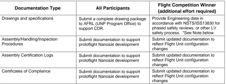
As stated in the preceding paragraphs, the documentation requirements for the winner of the Flight Competition will be greater than for the other universities. Table 2-1 shows a comparison of requirements for the Flight Competition winner vs. the remaining participants.
Table 2-1: Additional Documentation Requirements for the Flight Competition Winner Documentation Type All Participants Flight Competition Winner
(additional effort required) Drawings and specifications Submit a complete drawing package
to AFRL (UNP Program Office) to support CDR.
Provide Engineering data in
accordance with NSTS/ISS13830 for phased safety reviews, or other LV safety process. *See Note below. Assembly/Handling/Inspection
Procedures
Submit documentation to support protoflight Nanosat development
Submit updated documentation to reflect Flight Unit configuration changes
Assembly Certification Logs Submit documentation to support protoflight Nanosat development
Submit updated documentation to reflect Flight Unit configuration changes
Certificates of Compliance Submit documentation to support protoflight Nanosat development
Submit updated documentation to reflect Flight Unit configuration changes
Revision - Use or disclosure of data contained on this sheet is subject to UN5-0002 Documentation Type All Participants Flight Competition Winner
(additional effort required) Analysis Documentation
• Structural
• Thermal
• Pressure profile (venting)
• EMC
Complete structural analysis by PQR in accordance with UN-SPEC-12311, Rev. A, Stress Analysis Case Study, and Sections 8.1 and 8.4 of UN5-0001.
Complete thermal analysis by PQR in accordance with the Thermal Management expert area telecon and Section 8.4 of UN5-0001. Complete venting analysis by PQR in accordance with AIAA Paper 83-2600 and Section 8.5 of UN5-0001. Complete EMC analysis by PQR in accordance with Section 8.6 of UN5-0001.
Submit structural, thermal, venting and EMC properties data and analysis results to AFRL to support the development of integrated models
Test Documentation
• Test Plans
• Test Reports
• Manufacturer’s Test Data
• Test Procedures
• Problem Failure Reports
• Test Certification Logs
Submit documentation to support protoflight Nanosat development
Submit documentation to support Flight Unit development, and support environmental testing/documentation of the flight Nanosat at AFRL.
Formal Safety Documentation: inputs for launch vehicle Safety Reviews
Not Required Provide inputs to support
development of NASA Phase 2 and 3 safety documentation per NSTS/ISS 13830, or other safety documentation in support of a DoD expendable launch vehicle safety review process. *See Note below.
*Note: there is significant effort involved in developing documentation that satisfies the requirements of NSTS/ISS 13830. All universities are encouraged to read NSTS/ISS 13830, so that these requirements are clearly understood. NSTS/ISS 13830 can be found on the UNP website at www.universitynanosat.org.
2.2 Review & Approval of Program Documentation 2.2.1 University Review and Approval
Universities must provide requirements data, engineering definition, as-built, and qualification data as defined in Sections 2.1.2 through 2.1.4. These data shall be subjected to a disciplined internal review and approval process. In most cases, documents submitted by the universities to AFRL or other entity must be reviewed by at least two qualified individuals at the university as defined in Table 2-2. This table also indicates which signature sheets or forms are to be used for various types of documentation. Each form should clearly show who has reviewed and approved the document and in what capacity. Completed signature sheets must be kept on file at the university and provided to AFRL in support of the Flight Competition.
2.2.2 AFRL/DoD Review and Approval
Documentation submitted in support of the Flight Competition will be reviewed by AFRL and/or other government personnel as part of the Flight Competition, but only the winning team will have formal government review and concurrence in preparation for LV safety reviews and prior to acceptance of delivery
to AFRL for integrated environmental testing (see Figure 2-1). In cases where review and approval requirements are in conflict with hazard report requirements, the hazard report requirements shall supersede the requirements outlined in this document.
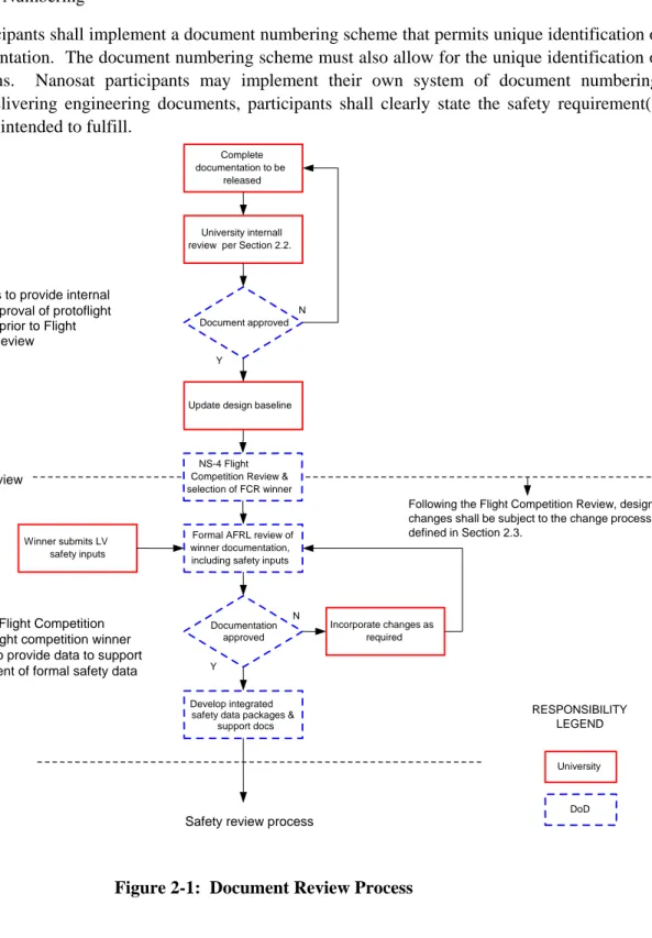
2.2.3 Document Numbering
The Nanosat participants shall implement a document numbering scheme that permits unique identification of all project documentation. The document numbering scheme must also allow for the unique identification of document revisions. Nanosat participants may implement their own system of document numbering; however, when delivering engineering documents, participants shall clearly state the safety requirement(s) that submittals are intended to fulfill.
Figure 2-1: Document Review Process
University internall review per Section 2.2.
Complete documentation to be released RESPONSIBILITY LEGEND DoD University Y N
Update design baseline Document approved
Flight Competition Review
Following the Flight Competition Review, design changes shall be subject to the change process defined in Section 2.3.
NS-4 Flight Competition Review & selection of FCR winner
Formal AFRL review of winner documentation, including safety inputs Winner submits LV safety inputs Documentation approved Phase 2 / 3 or LV Safety Review Incorporate changes as required Y N Develop integrated safety data packages &
support docs
Safety review process All universities to provide internal
review and approval of protoflight Nanosat data prior to Flight Competition Review
Following the Flight Competition Review, the flight competition winner will continue to provide data to support the development of formal safety data packages
Revision - Use or disclosure of data contained on this sheet is subject to the restrictions on the title page of this document. UN5-0002 Table 2-2: University Documentation Review and Approval
Type Subtype Review & Signature Req’s
(See Roles, Note 3) Signature Provisions Sample Form
Nanosatellite Requirements Flow-Down PREP1, REA(s), SY, PM Signature Sheet
Include in document (Ref. Page i of this document for an example of signature sheet.)
Component Specifications PREP1, REA(s), SY, PM Signature Sheet Include in document Program
Requirements
Deviations, Waivers PREP1, REA(s), SY, PM Request for Deviation / Waiver (RFD/W) Exhibits C-1, C-2
Drawings and Specifications PREP1, REA(s), SY Signature Sheet Include in document Engineering
Definition Engineering Changes PREP1
, REA(s), SY Engineering Change Request (ECR) Exhibits C-7, C-8, C-9
Assembly Activity FAB, QA Certification Log Exhibits C-3, C-4
As Built
Configuration Manufacturing Deviation FAB, REA(s), QA, SY Manufacturing Deviation Notice (MDN) Exhibits C-5, C-6 Analysis (e.g., structural, thermal) PREP1, REA(s), SY Signature Sheet Include in document Test Plans/Procedures/Reports/ PREP1, IT, QA, SY, PM2 Signature Sheet Include in document
Test Activity PREP1, IT, QA Certification Log Exhibits C-3, C-4
Problem/Failure PREP1, IT, QA, REA(s), SY, PM Problem Failure Report Exhibits C-10, C-11
Qualification Data
FSDP, GSDP, SVP, FCP, MSVP or
other LV safety review document inputs PREP 1
, REA(s), SY, PM Signature Sheet Include in document
1. Depending on the organization, functional positions may overlap. For example, the preparer of an electrical component specification may be the project’s electrical REA; the originator of the program’s structural analysis may be the project’s structural REA; and the originator of the system test plan may be the student test engineer (IT). 2. PM signature for final report only
3. Roles:
• PREP – Any qualified individual who serves as the preparer of technical data or who initiates an engineering action. The preparer is responsible for obtaining supplementary engineering review and maintains overall responsibility if supplementary review is not sought.
• REA - Responsible Engineering Authority: Any qualified individual that reviews and approves the program’s technical data, especially when the review is conducted with respect to a particular discipline. There may be more than one applicable REA per document.
• FAB – Fabricator/Assembler – The individual(s) responsible for fabricating or assembling the part in question.
• IT – Integration and Test – The individual(s) responsible for planning, executing, and documenting integration and testing of payload elements.
• SY - Systems Engineer – The individual(s) responsible for defining system requirements and for ensuring the overall satisfaction of these requirements. Also responsible for identifying and resolving conflicts and discrepancies of an engineering nature.
• QA - Quality Assurance (QA) – The individual(s) responsible for ensuring that parts are manufactured according to engineering specification. For the University Nanosat Program, QA may be performed by any individual that is independent of the Fabricator/Assembler and that has either witnessed the proper assembly of the part or can confirm that the part complies with all applicable engineering specifications.
• CM - Configuration Manager – The individual(s) responsible for ensuring the accuracy of as-built documentation and for archiving all documentation related to the history of a part.
2.3 Change Management
All universities are encouraged to implement a formal change management process to minimize the potential for design errors and requirements violations. The use of a formal change management process as described in Sections 2.3.1 through 2.3.3 is required only for the winner of the Flight Competition.
2.3.1 Waivers and Deviations for Program Requirements
University Nanosat Hardware is subject to requirements specified in AFRL Document UN5-0001, Nanosat-5 Users’ Guide, PSC Document 4000389, Rev. A, Motorized Lightband Specification, and all applicable program requirements referenced in this or any other program requirements documentation, including the UNP website. If the hardware fails to meet these requirements, then the university must request a deviation or waiver to these requirements via a Request for Deviation/Waiver (RFD/W) Form (see Exhibit C-1).
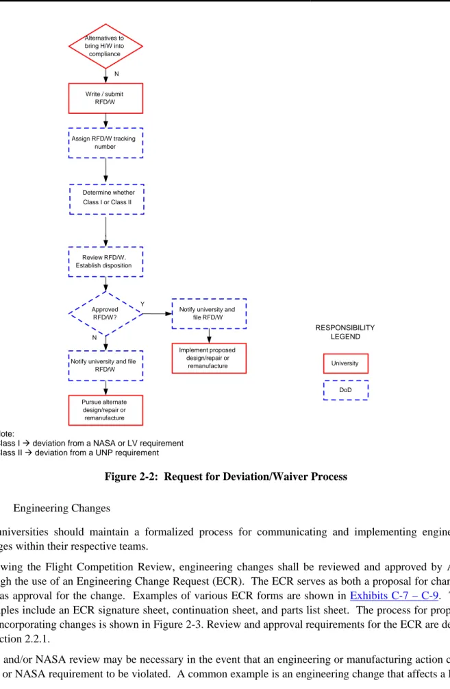
The process for completing an RFD/W Form is shown in Figure 2-2. The Preparer/REA must state the reason for the RFD/W along with a reference to the specific requirement. The Preparer/REA should also note whether the requirement is a UNP, NASA, LV or other requirement (Class I vs. Class II). AFRL would then review the RFD/W indicating its approval or disapproval.
Note: The UNP Program Office fully expects the universities to meet all program and technical requirements. The use of the RFD/W is considered a last resort after all other methods of resolution have been exhausted.
Revision - Use or disclosure of data contained on this sheet is subject to UN5-0002 Note:
Class I Æ deviation from a NASA or LV requirement Class II Æ deviation from a UNP requirement
Figure 2-2: Request for Deviation/Waiver Process 2.3.2 Engineering Changes
All universities should maintain a formalized process for communicating and implementing engineering changes within their respective teams.
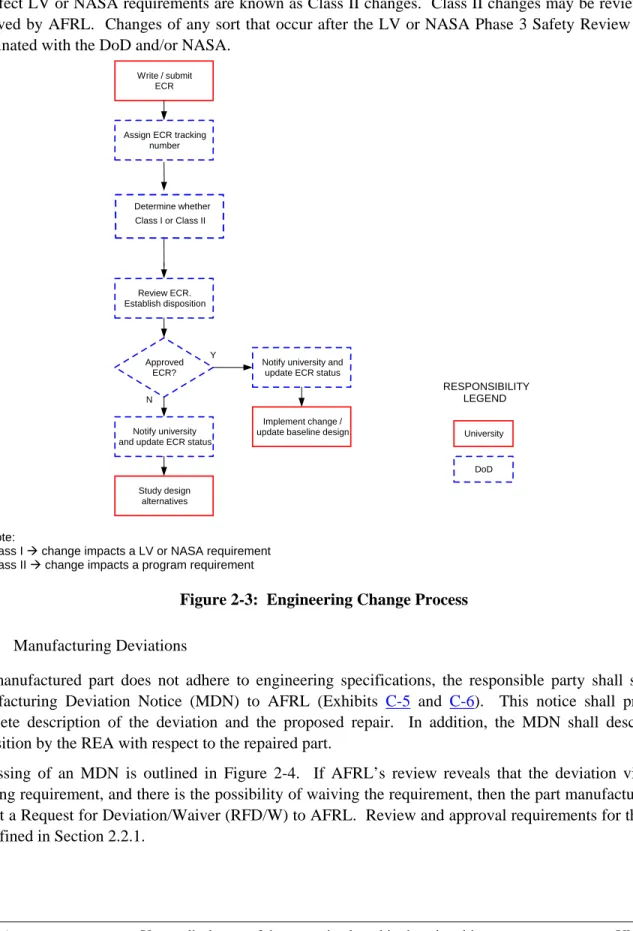
Following the Flight Competition Review, engineering changes shall be reviewed and approved by AFRL through the use of an Engineering Change Request (ECR). The ECR serves as both a proposal for change as well as approval for the change. Examples of various ECR forms are shown in Exhibits C-7 – C-9. These examples include an ECR signature sheet, continuation sheet, and parts list sheet. The process for proposing and incorporating changes is shown in Figure 2-3. Review and approval requirements for the ECR are defined in Section 2.2.1.
SMC and/or NASA review may be necessary in the event that an engineering or manufacturing action causes a LV or NASA requirement to be violated. A common example is an engineering change that affects a LV or
Write / submit RFD/W Assign RFD/W tracking number Review RFD/W. Establish disposition Approved RFD/W?
Notify university and file RFD/W Pursue alternate design/repair or remanufacture Implement proposed design/repair or remanufacture Notify university and
file RFD/W RESPONSIBILITY LEGEND DoD University Y N Alternatives to bring H/W into compliance N Determine whether Class I or Class II
NASA requirement (see Section 2.3). Such a change is known as a Class I change. In such instances, the AFRL will seek approval from the LV provider or NASA on behalf of the university team. Changes that do not affect LV or NASA requirements are known as Class II changes. Class II changes may be reviewed and approved by AFRL. Changes of any sort that occur after the LV or NASA Phase 3 Safety Review must be coordinated with the DoD and/or NASA.
Note:
Class I Æ change impacts a LV or NASA requirement Class II Æ change impacts a program requirement
Figure 2-3: Engineering Change Process 2.3.3 Manufacturing Deviations
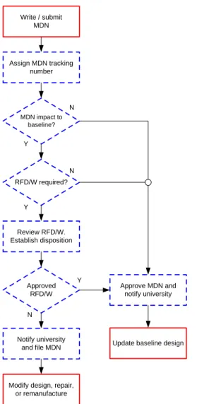
If a manufactured part does not adhere to engineering specifications, the responsible party shall submit a Manufacturing Deviation Notice (MDN) to AFRL (Exhibits C-5 and C-6). This notice shall provide a complete description of the deviation and the proposed repair. In addition, the MDN shall describe the disposition by the REA with respect to the repaired part.
Processing of an MDN is outlined in Figure 2-4. If AFRL’s review reveals that the deviation violates a standing requirement, and there is the possibility of waiving the requirement, then the part manufacturer shall submit a Request for Deviation/Waiver (RFD/W) to AFRL. Review and approval requirements for the MDN are defined in Section 2.2.1.
Write / submit ECR
Assign ECR tracking number Review ECR. Establish disposition Approved ECR? Notify university and update ECR status
Study design alternatives
Implement change / update baseline design
Notify university and update ECR status
RESPONSIBILITY LEGEND DoD University Y N Determine whether Class I or Class II
Revision - Use or disclosure of data contained on this sheet is subject to UN5-0002 MDN impact to baseline? Write / submit MDN Assign MDN tracking number Review RFD/W. Establish disposition Approved RFD/W Notify university and file MDN
Modify design, repair, or remanufacture
Update baseline design Approve MDN and notify university RESPONSIBILITY LEGEND DoD University N Y Y N RFD/W required? N Y
Figure 2-4: Manufacturing Deviation Review Process
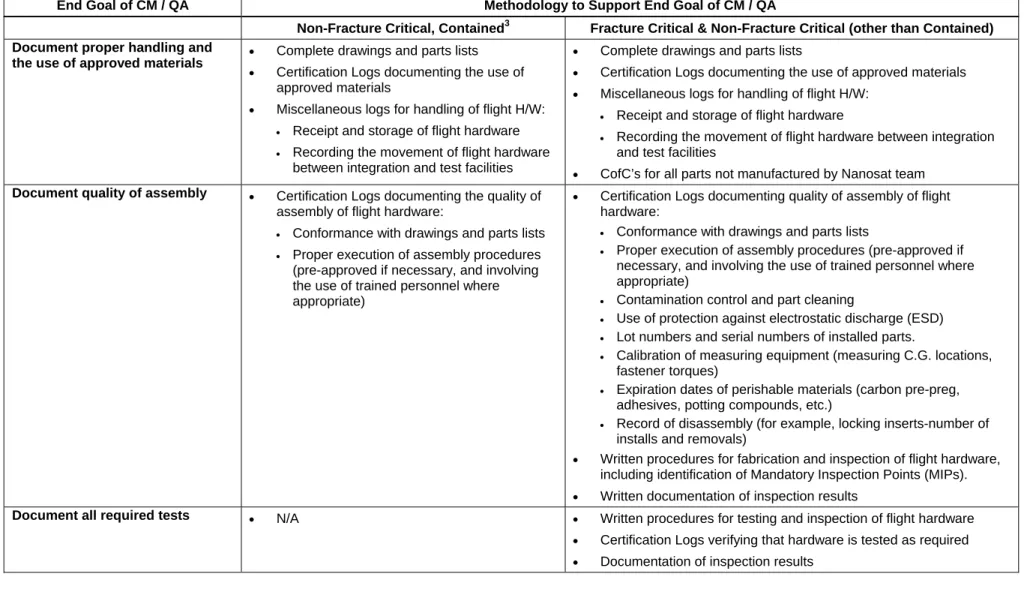
2.4 Special Documentation Requirements: Non-Fracture Critical Hardware
The amount of documentation required to verify hardware acceptability varies with the potential hazard associated with the hardware in question. For fracture critical hardware (i.e. hardware whose fracture or failure will result in a catastrophic failure as defined in NSTS 1700.7B), a significant amount of as-built and qualification documentation is required to verify part acceptability per NASA-STD-5003. This includes a detailed accounting of the stages of assembly and testing. By contrast, non-fracture critical hardware (particularly contained hardware) is not subject to the same level of analysis and testing. The documentation requirements for such hardware are therefore less than for fracture critical hardware.
Table 2-3 provides a summary of as-built and qualification data used to support the following end goals: • Proof of proper handling and the use of approved materials
• Proof of quality of assembly • Proof of all required tests
This table shows examples of the level of documentation required for non-fracture critical, contained hardware versus other hardware.
Table 2-3: As-Built/As-Tested Documentation Requirements for Parts End Goal of CM / QA Methodology to Support End Goal of CM / QA
Non-Fracture Critical, Contained3 Fracture Critical & Non-Fracture Critical (other than Contained) Document proper handling and
the use of approved materials •
Complete drawings and parts lists
• Certification Logs documenting the use of approved materials
• Miscellaneous logs for handling of flight H/W: • Receipt and storage of flight hardware • Recording the movement of flight hardware
between integration and test facilities
• Complete drawings and parts lists
• Certification Logs documenting the use of approved materials
• Miscellaneous logs for handling of flight H/W: • Receipt and storage of flight hardware
• Recording the movement of flight hardware between integration and test facilities
• CofC’s for all parts not manufactured by Nanosat team Document quality of assembly • Certification Logs documenting the quality of
assembly of flight hardware:
• Conformance with drawings and parts lists • Proper execution of assembly procedures
(pre-approved if necessary, and involving the use of trained personnel where appropriate)
• Certification Logs documenting quality of assembly of flight hardware:
• Conformance with drawings and parts lists
• Proper execution of assembly procedures (pre-approved if necessary, and involving the use of trained personnel where appropriate)
• Contamination control and part cleaning
• Use of protection against electrostatic discharge (ESD) • Lot numbers and serial numbers of installed parts.
• Calibration of measuring equipment (measuring C.G. locations, fastener torques)
• Expiration dates of perishable materials (carbon pre-preg, adhesives, potting compounds, etc.)
• Record of disassembly (for example, locking inserts-number of installs and removals)
• Written procedures for fabrication and inspection of flight hardware, including identification of Mandatory Inspection Points (MIPs).
• Written documentation of inspection results
Document all required tests • N/A • Written procedures for testing and inspection of flight hardware
• Certification Logs verifying that hardware is tested as required
• Documentation of inspection results
3
Revision - Use or disclosure of data contained on this sheet is subject to UN5-0002
3. QUALITY ASSURANCE
3.1 Supplier Integrity
3.1.1 Fasteners
There are special requirements for ensuring the integrity of fasteners supplied by outside sources. These requirements are defined in JSC 23642 JSC Fastener Integrity Testing Program (see www.universitynanosat.org). After delivery to the user, the responsibility for configuration control rests with the organization in possession as stated in Section 3.2.
3.1.2 Other Hardware
Hardware purchased from outside suppliers is subject to the documentation requirements stated in Section 2.1.3. Certificates of compliance are required for all purchased hardware to ensure that the hardware meets all applicable specifications. Section 2.1.3 lists minimum information requirements for C of C’s.
3.2 Control of Hardware
The responsibility for control of hardware depends on the phase of development and the corresponding location of the hardware. Generally speaking, the responsibility rests with the organization currently in possession of the hardware unless otherwise specified by contract.
The responsible organization should take all necessary steps to control the environment in which materiel is stored, assembled, integrated, and tested with respect to the following:
3.2.1 Cleanliness
Per UN5-0001, Nanosat participants are responsible for ensuring the cleanliness of hardware under their control:
• Use of clean assembly facilities, such as rooms, tents, and tables where applicable
• Use of protective clothing to prevent contaminants from being deposited on flight hardware • Cleaning of parts prior to installation
• Use of vacuum sealed plastic during shipping
• Bakeout of all applicable parts to minimize outgassing • Use of procedures to prevent damage due to ESD.
Universities should establish a training program for students needing access to clean facilities.
3.2.2 Access
In cases where controlled access is required the responsible authority shall implement the necessary physical security to prevent unauthorized access. A sign-in/sign-out and escort system shall be implemented and a training program established to ensure that access is provided only to personnel who are skilled in the proper handling of the hardware. Parts destined for use on flight hardware shall be stored in locked cabinets to prevent unauthorized access. Handling of flight parts shall be traceable through handling certification logs (“travelers”).
3.2.3 Ground Safety
It is of utmost importance for all individuals with access to the hardware to be cognizant of safe handling procedures. All Nanosat participants shall adhere to safety guidelines established by their respective organizations. For ground activities conducted at the NASA-KSC, Nanosat participants shall adhere to the safety requirements defined in NASA document KHB 1700.7C, Space Shuttle Payload Ground Safety Handbook. For ground activities conducted at the Eastern or Western Launch Ranges (CCAFS or VAFB), Nanosat participants shall adhere to the safety requirements defined in AFSPC MAN 91-710. Though ensuring ground safety is ultimately the responsibility of the university, AFRL will provide guidance to the Flight Nanosat team on satisfaction of ground safety requirements.
3.2.4 Transport
The university shall provide packing and shipping container(s) that will protect against damage during transport to the integration site. The development and approval of handling procedures for some hardware is a safety requirement (e.g., handling procedures for composite panels).
Any special procedures or notable events that occur during transport shall be recorded in the appropriate certification log. Examples include, but are not limited to:
• Special handing procedures (lifting, application and removal of protective materials, gas purges, etc.) • Excessive shock levels recorded during transport.
3.3 Inspections
3.3.1 Two-Person Build & Verify
Nanosat participants shall clearly document all stages of flight hardware development as defined in Section 2.1.3. Universities shall use a two-person build and verify approach to ensure that university-built hardware is assembled and tested according to approved procedures, drawings, and specifications. For each significant step in the assembly procedures, two sets of handwritten initials shall be included: one each from two individuals who participated in the manufacture and/or inspection of the part or subassembly and who can confirm that it complies with all applicable engineering data. Universities shall thoroughly document all assembly/build processes via photographic record.
The Nanosat Separation System supplier and AFRL shall adhere to existing internal processes for verification of their respective hardware.
3.3.2 Mandatory Inspection Points
Mandatory Inspection Points (MIP’s) are critical steps during assembly and I&T that have a direct bearing on the control of a hazard but will not be independently verified by subsequent test or inspection and must therefore be independently verified in real-time. It follows that MIP’s generally involve 1) hardware that carries an inherent potential for catastrophic failure 2) hardware that is difficult to inspect after final assembly, and/or 3) hardware whose assembly is process sensitive. The university and AFRL shall jointly be responsible for the identification of MIP’s through the design process. The university and AFRL shall be responsible for tracking and ensuring that the MIP’s are adequately inspected.
AFRL must review and approve MIP’s identified by the universities or the separation system supplier. AFRL will also be the primary agency responsible for independent inspection of MIP’s. SMC/STP, NASA, and/or
Revision - Use or disclosure of data contained on this sheet is subject to UN5-0002 other LV provider may also participate in the inspection process. Successful completion of MIP’s shall be noted in the assembly/test certification logs.
To facilitate planning, the university and the separation system supplier(s) must provide AFRL with a schedule of MIP’s four weeks prior to execution of the first MIP.
3.4 Training Requirements
All aspects of Nanosat design, assembly and/or I&T must be conducted using qualified personnel. Personnel at AFRL and the separation system supplier must have an engineering degree and a history of related experience. Individuals involved in assembly and I&T must have a history of related experience.
University students may be involved in some aspects of the satellite integration and test activities at AFRL and the launch site. Where this is the case, students must be familiar with the hardware design as well as with the assembly, test, and inspection procedures used to integrate and test the hardware. Individuals responsible for the integration and test of university-built hardware must be identified in advance, and their initials must appear on the appropriate certification logs. For certain critical procedures, such as the installation of the Lightband System, students must be formally trained and certified by the Planetary Systems Corporation.
ACRONYMS
AIAA American Institute of Aeronautics and Astronautics AFOSR Air Force Office of Scientific ResearchAFRL Air Force Research Laboratory CCAFS Cape Canaveral Air Force Station CDR Critical Design Review
C of C Certificate of Compliance CG Center of Gravity
CVCM Collectable Volatile Condensable Material
CM Configuration Management
DoD Department of Defense ECR Engineering Change Request
EGSE Electrical Ground Support Equipment EMC Electromagnetic Compatibility EMI Electromagnetic Interference
EN Engineering Notice
ESD Electro-Static Discharge FCP Fracture Control Plan
FCR Flight Competition Review FS Factor of Safety
GSE Ground Support Equipment I&T Integration and Test ICD Interface Control Document
ITAR International Traffic in Arms Regulations JSC Johnson Space Center
KAFB Kirtland Air Force Base KSC Kennedy Space Center
LV Launch Vehicle
MDN Manufacturing Deviation Notice
MGSE Mechanical Ground Support Equipment MIP Mandatory Inspection Point
MS Margin of Safety
MSVP Mechanical Systems Verification Plan Nanosat Nanosatellite
NASA National Aeronautics and Space Administration NS-5 Nanosat-5
NSS Nanosat Separation System
Revision - Use or disclosure of data contained on this sheet is subject to UN5-0002 PDR Preliminary Design Review
PFR Problem Failure Report POC Point of Contact
PQR Proto-Qualification Review PRD Payload Requirements Document PSC Planetary Systems Corporation PSRP Payload Safety Review Panel
QA Quality Assurance
REA Responsible Engineering Authority
RF Radio Frequency
RFD/W Request for Deviation/Waiver RVM Requirements Verification Matrix RVP Requirements Verification Plan SCC Stress Corrosion Cracking SCR System Concept Review
SMC/STP USAF Space and Missile Systems Center, Space Test Program (STP) SHCS Socket Head Cap Screw
SIP Satellite Interface Plane
SR Status Review
SSP Satellite Separation Plane STP Space Test Program SVP Structural Verification Plan TBD To Be Determined
TML Total Mass Loss
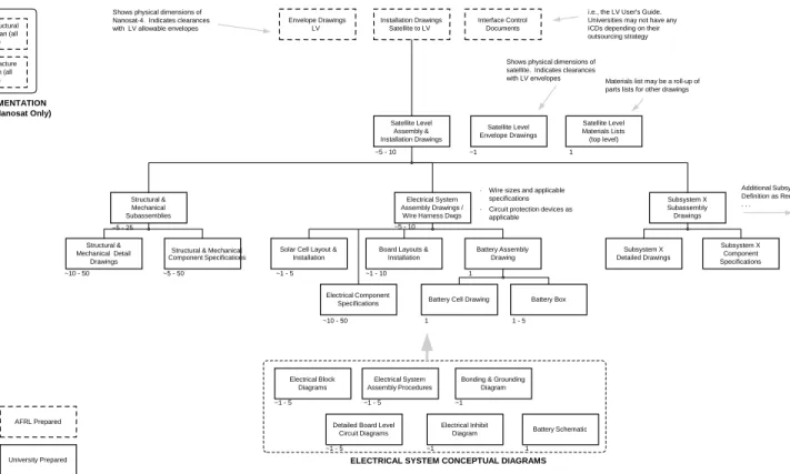
Appendix A. Program Documentation, UN-5
Figure A-1: Nanosat-5 Document Tree
Satellite Level Materials Lists (top level) Structural & Mechanical Subassemblies Satellite Level Envelope Drawings Interface Control Documents Satellite Level Assembly & Installation Drawings
Materials list may be a roll-up of parts lists for other drawings
Battery Schematic Battery Cell Drawing
Battery Assembly Drawing Electrical System
Assembly Drawings / Wire Harness Dwgs
i.e., the LV User's Guide. Universities may not have any ICDs depending on their outsourcing strategy
Structural & Mechanical Detail
Drawings ~10 - 50
Structural & Mechanical Component Specifications
NOTES:
1. Approximate number of drawings depends on individual design and outsourcing strategy 2. All drawings should have parts lists showing constituent parts, materials, and quantities 3. All drawings should reference applicable processes
4. Circuit Protection measures must be called out on applicable drawings.
5. Structural & Mechanical drawings should also include drawings of GSE used for ground handling and testing 6. Electrical system drawings should also include drawings of EGSE used for testing and servicing
7. The flight competition winner will be responsible for supplying LV safety package inputs to AFRL
8. Test Plans, Procedures, and Reports are for all university testing, including modal frequency, mass properties, envelope verification, and functional testing
Structural & Mechanical System Assembly Procedures Test Plans Test Procedures (including As-Run) Test Reports Installation Drawings Satellite to LV Envelope Drawings LV Battery Box Structural Analysis Certification Logs
· Wire sizes and applicable specifications · Circuit protection devices as
applicable Integrated Flight
Safety Data Package (all phases)
Integrated Structural Verification Plan (all
phases)
Integrated Mechanical Systems Verification
Plan (all phases)
Integrated Fracture Control Plan (all
phases)
Shows physical dimensions of satellite. Indicates clearances with LV envelopes Shows physical dimensions of
Nanosat-4. Indicates clearances with LV allowable envelopes
~5 - 25 ~5 - 50 ~5 - 10 ~1 1 ~1 - 5 ~1 - 10 ~5 - 10 ~1 - 5 1 1 1 1 - 5 Electrical Block Diagrams Electrical System Assembly Procedures
Bonding & Grounding Diagram ~1
~1 - 5 ~1 - 5
Solar Cell Layout & Installation
Electrical Component Specifications
Detailed Board Level Circuit Diagrams
Board Layouts & Installation
ELECTRICAL SYSTEM CONCEPTUAL DIAGRAMS
Subsystem X Subassembly Drawings Subsystem X Detailed Drawings Subsystem X Component Specifications Electrical System Assembly Procedures Subsystem X Assembly Procedures Electrical Inhibit Diagram ~1 INTEGRATED PAYLOAD SAFETY DOCUMENTATION
(PSRP-Specific—Flight Nanosat Only) AS-BUILT DOCUMENTATION Additional Subsystem Definition as Required . . . QUALIFICATION DATA Deviation Notices Problem Failure Reports ~10 - 50 Certificates of Compliance University Prepared AFRL Prepared
Revision - Use or disclosure of data contained on this sheet is subject to UN5-0002 Appendix B. Certificates of Compliance
Revision - Use or disclosure of data contained on this sheet is subject to UN5-0002 Exhibit B-3: Certificate of Compliance Example 3
Revision - Use or disclosure of data contained on this sheet is subject to the restrictions on the title page of this document. UN5-0002 Exhibit C-1. Request for Deviation/ Waiver Form
REQUEST FOR
DEVIATION/WAIVER
WBS (Note: Univ. structure, if
applicable.)
1OF____
REASON FOR WAIVER REQUEST:
(Note: Include all relevant technical information, to include drawings, schematics, diagrams, photographs, test data, test reports, analysis reports, etc. Provide sufficient detail to completely describe the problem and proposed resolution.)
PROPOSED REQUIREMENTS WAIVER / IMPACT ASSESSMENT (SYSTEMS & SCHEDULE):
APPLICABLE REQUIREMENT (DOC., PARA.) (Note: Most likely a NS-4 User’s Guide and/or derivative requirement.)
DISAPPROVAL SIGNATURE APPROVAL SIGNATURE DATE CLASS II CLASS I
REVIEW SIGNATURES (Univ.)
ORIGINATOR / DATE
REA / DISCIPLINE / DATE
I&T MANAGER / DATE
SAFETY / DATE
SYSTEMS ENGINEER / DATE
CONFIGURATION MANAGER / DATE REA / DISCIPLINE / DATE
REA / DISCIPLINE / DATE
REA / DISCIPLINE / DATE
PROGRAM MANAGER / DATE
VSSV-FORM-RFDW-001 REV. 2/18/00
DISPOSITION (Completed by AFRL)
· CLASS I CHANGES, PROGRAM MANAGER APPROVAL/DISAPPROVAL REQUIRED
· CLASS II CHANGES--REQUIREMENTS GOVERNING BODY APPROVAL/DISAPPROVAL REQUIRED
REQUEST FOR
DEVIATION/WAIVER
RFD/W NUMBER CONTINUATION SHEET _____ OF ____ VSSV-FORM-RFDW-002 REV. 12/16/99Revision - Use or disclosure of data contained on this sheet is subject to the restrictions on the title page of this document. UN5-0002
CERTIFICATION LOG
CERT LOG NO. PURPOSE OF LOG PROJECT NAME DATE
FAB / ASSY I&T
PART NUMBER NOMENCLATURE QTY S/N H/W TYPE
FLT FLT QUAL
NONFLT ETU
ASSY DWG NO. REV ASSY P/L NO REV ASSY W/L NO. REV
NEXT ASSY P/N PREV ASSY CERT LOG NO.. NEXT ASSY CERT LOG NO.
MFG APPROVAL/DATE 2 QA APPROVAL/DATE 2 ENGINEERING APPROVAL/DATE 2 CM APPROVAL/DATE 2
UNINCORP ECR REV DWG/DOC AFFECTED S/N AFFECTED INCORP BY
OPER/DATE 2 QA VERIF/DATE 2
EVENT NO. RESP.ORG EVENT DESCRIPTION1 INSP BY/DATE2 PROB RCD ITEM NO. CLOSE OUT
BY/DATE
QC FINAL QA ACCEPTANCE
RETROFIT IS NO. PART NUMBER NOMENCLATURE SERIAL NUMBER
Notes:
1 For other events see continuation sheets
2 Field must contain handwritten signature and date
CERTIFICATION LOG
(CONTINUATION SHEET)
SHEET OF
CERT LOG NO. PART NUMBER NOMENCLATURE S/N
EVENT NO. RESP ORG. EVENT DESCRIPTION
(FOR PARTS INSTALLED, INCLUDE LOT # AND S/N IF APPLICABLE)
PERF BY / DATE 1 INSP BY / DATE 1 PROB RCD ITEM NO. 1 CLOSE OUT BY / DATE 1
1 Field must contain handwritten initials and date
Revision - Use or disclosure of data contained on this sheet is subject to the restrictions on the title page of this document. UN5-0002 Exhibit C-5: Manufacturing Deviation Notice
REASON FOR CHANGE:
(Note: Include all relevant technical information, to include drawings, schematics, diagrams, photographs, test data, test reports, analysis reports, etc. Provide sufficient detail to completely describe the problem and proposed resolution.)
REVIEW SIGNATURES
MANUFACTURING
DEVIATION NOTICE
MDN NUMBER PART DESCRIPTION: WBS SHEET 1OF____CORRECTIVE ACTION TAKEN:
MANUFACTURING COMPLIANCE RECORD IS A CHANGE FOR FUTURE
UNITS REQUIRED?
PART/ASSEMBLY NO.: S/N
DRAWING NO.: REV.
NO YES
ORIGINATOR / DATE
REA / DISCIPLINE / DATE
I&T MANAGER / DATE
SAFETY / DATE
SYSTEMS ENGINEER / DATE
CONFIGURATION MANAGER / DATE REA / DISCIPLINE / DATE
REA / DISCIPLINE / DATE
REA / DISCIPLINE / DATE
PROGRAM MANAGER / DATE
DISAPPROVAL SIGNATURE APPROVAL SIGNATURE DATE VSSV-FORM-MDN-001 REV. 02/18/00 DISPOSITION
· CLASS I CHANGES, PROGRAM MANAGER APPROVAL/DISAPPROVAL REQUIRED
· CLASS II CHANGES--REQUIREMENTS GOVERNING BODY APPROVAL/DISAPPROVAL REQUIRED
CLASS II CLASS I
MANUFACTURING
DEVIATION NOTICE
MDN NUMBER CONTINUATION SHEET ____ OF ____ VSSV-FORM-MDN-002 REV. 12/16/99Revision - Use or disclosure of data contained on this sheet is subject to the restrictions on the title page of this document. UN5-0002 Exhibit C-7: Engineering Change Request Form
REVIEW SIGNATURES
ENGINEERING
CHANGE REQUEST
WBS 1 OF ____
REASON FOR CHANGE:
(Note: Include all relevant technical information, to include drawings, schematics, diagrams, photographs, test data, test reports, analysis reports, etc. Provide sufficient detail to completely describe the problem and proposed resolution.)
AFFECTED DOCUMENTS (DOC. NUMBER, REVISION, TITLE):
DISPOSITION
· CLASS I CHANGES, PROGRAM MANAGER APPROVAL/DISAPPROVAL REQUIRED
· CLASS II CHANGES--REQUIREMENTS GOVERNING BODY APPROVAL/DISAPPROVAL REQUIRED
DISAPPROVAL SIGNATURE APPROVAL
SIGNATURE DATE
DESCRIPTION OF CHANGES / IMPACT ASSESSMENT (SYSTEMS & SCHEDULE): CLASS I CLASS II
ORIGINATOR / DATE
REA / DISCIPLINE / DATE
I&T MANAGER / DATE
SAFETY / DATE
SYSTEMS ENGINEER / DATE
CONFIGURATION MANAGER / DATE REA / DISCIPLINE / DATE
REA / DISCIPLINE / DATE
REA / DISCIPLINE / DATE
PROGRAM MANAGER / DATE
VSSV-FORM-ECR-001 REV. 2/18/00
ENGINEERING
CHANGE REQUEST
____ OF ____REV.
PROCURED
PART NUMBER NOTE
TYPE OF CHANGE FIND NUMBER ECR NUMBER CONTINUATION SHEET
BILL OF MATERIALS / PARTS LIST
ADD DELETE CHNG FROM CHNG TO QUANTITY CIRCUIT SYMBOLS OR REFERENCE DESIGNATORS VSSV-FORM-ECR-003 REV. 2/18/00 WBS EFFECTIVITY
Revision - Use or disclosure of data contained on this sheet is subject to the restrictions on the title page of this document. UN5-0002
ENGINEERING
CHANGE REQUEST
REV. ECR NUMBER CONTINUATION SHEET ____ OF ____ VSSV-FORM-ECR-002 REV. 12/16/99PROBLEM FAILURE REPORT
PFR NO. PROJECT NAME DATE
PART NUMBER NOMENCLATURE QTY S/N H/WTYPE
FLT FLT QUAL
NONFLT ETU
TEST PROCEDURE NUMBER PARAGRAPH NUMBER FOUND DURING
TEST INSPECTION
ORIGINATOR / DATE 1 ASSIGNED TO / DATE
DESCRIPTION OF FAILURE
(Note: Include all relevant technical information, to include drawings, schematics, diagrams, photographs, test data, test reports, analysis reports, etc. Provide sufficient detail to completely describe the problem and proposed resolution.)
CORRECTIVE ACTION TAKEN
COST IMPACT SCHEDULE IMPACT
TRANSITIONED TO PFR# ECN# STR# RFD/W# CERT LOG # MDN #
COGNIZANT ENGINEER / DATE 1 QA / DATE 1 CUSTOMER / DATE 1 APPROVAL / DATE 1
Notes:
1
Field must contain handwritten signature and date
Revision - Use or disclosure of data contained on this sheet is subject to the restrictions on the title page of this document. UN5-0002
PROBLEM FAILURE REPORT
(CONTINUATION SHEET)
PFR NO. PROJECT NAME PART NUMBER NOMENCLATURE S /N
DESCRIPTION OF FAILURE