A Spinor Method of Solution of Manipulators' Inverse
Kinematics Problem with Rotational Pairs
Hüseyin ÖNAL
Abstract: A new method and algorithm of solution of multijoint
manipulators with rotational pairs inverse kinematic problem was created. The method is based on the principally new approach-spinor representation of the spatial generalized rotations. One of the advantages of the method is that it allows elaborating formulation of technological tasks for manipulators in terms of Cartesian coordinates instead of traditional angles' terms. Besides the method allows using only one (absolute) coordinate system and does not require a set of different (relative) coordinate systems. It provides easy, reliable and efficient way of solution of inverse kinematics problem of multijoints manipulators with rotational pairs.
Keywords: spinors, rotations, Euler's angles, basic representations, kinematics inverse problem, orthogonal transformations
Introduction
I.M., Milnos R.A., Shapiro Z.A., (1972)). This method, firstly, is for description of separate concrete rotations with the zero center (placed at the beginning of coordinates), and, secondly, it doesn't allow to express Euler angles in a form of coordinate functions of the three points determining rotating: center, beginning and final.
Hence, the purpose of the present work is to develop a new method of solution of the inverse kinematics problem for spatial mechanisms with rotational pairs based on the spinor presentation of three dimensional rotation groups.
Definition of the problem
In the works (Milnikov A.A., Prangishvili A.I., Rodonaia I.D. (2005) - Milnikov A., Onal H., Partskhaladze R., Rodonaia I., (2004)), on the basis of spinor model of three-dimensional Euclidian space the simple relationships between elements of three-dimensional orthogonal matrix of the basic presentation and Eulerian angles on the one side and coordinates of the starting and final points of rotation, on the other side have been obtained. The mentioned results allowed developing a new method and an algorithm of solutions of the inverse problem for manipulators with rotational pairs.
Let us consider the mechanism (manipulator) with n rotational pairs, the principal diagram of which is given in fig.1. We apply one system of coordinates which may be chosen quite arbitrarily.
Figure 1 principal diagram of multijoints manipulator with rotational pairs: y-goal point of manipulator's rotation
The new algorithm leads to the formulization of the inverse task 1
different from the traditional one :
Given: Cartesian coordinates of all n joints
1 2 3 1
coordinates of the point y(y, y, y), where the manipulator final point xn(xn, 2 3
xn, xn) should be moved;
1 2 3
Required to determine: new positions xi(xi, xi, xi) (i=1,…,n-1) ; of all intermediate joints and Eulerian angles θ , ψ and φ (i=1,…,n) of all i i i manipulator segments, providing rotation of rotational joints of the final
1 2 3 1 2 3 1 2 3
one xn(xn, xn, xn) into y(y, y, y) and intermediate ones xi(xi, xi, xi) into 1΄ 2΄ 3΄
x΄ (i x i, x i, x i) (i=1,…,n-1).
To solve the formulized problem an algorithm consisting of two stages has been developed.
The following important circumstances should be pointed out. The nature of spinor method enables to work with Cartesian coordinates and use the unique system of coordinate which presents indubitable advantage compared with the classical method requiring to formulate the tasks for manipulators in terms of rotation angle.
Principal Part
Calculation of Euler angles for a Three-Member Manipulator with Rotational Pairs
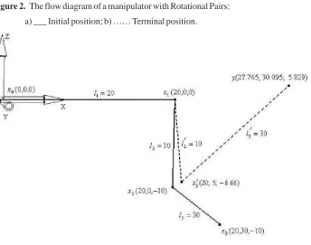
The flow diagram of such a manipulator is shown in Figure 3.1. The initial positions of the manipulator joints are given as follows: x0(0,0,0);
x1(20,0,0); x2(20,0,-10); x3(20,30,-10).The joint lengths are equal to l1=20,
l2=10 and l3=20. It is required to move the terminal point of the manipulator to the position y=(27.765,30.095,5.829).
It is not difficult to see that by giving the initial positions of the manipulator joints in this manner we have succeeded in obtaining the following relative positions of the joints: the first joint (x0 - x1) is positioned
1 1
along the Ox-axis, the second joint (x1- x2) is positioned in the plane x = 20 2 3
(parallel to the Ox x-plane), and the third joint (x - x) is orthogonal to the 1 2 3
Moreover, since the pairs are rotational, the first joint can rotate 3
only in the plane x = 0, the second joint – in the plane orthogonal to the 3
plane x = 0, and the third joint – in the plane orthogonal to the second plane. The solution of this problem by means of the spinor method is carried out by the same algorithm as was used for the solution of problems of manipulators with spherical pairs[A. Milnikov, H. Onal, C. Erguven, I. Rodonaia., (2006)]. The only difference consists in that in this case the plane should be replaced by the equation of the plane w h e r e rotation is to be performed. If the plane of rotation centers was previously used only for the purpose of solving the nonlinear system (3.1), now the equation of the rotation plane is the necessary restriction (constraint) imposed on joint motion.
In the context of the problem under consideration, the succession of calculations is as follows.
We obviously see that joint 2 cannot serve as the center of rotation
x3" y and therefore we should define its such position (if it exists) that satisfies the above conditions. To this end we solve the system
;
;
, (1)
2 i i
Where А1 = 1 А2 = А3 =0; l2 = 10; l3 = 30; x1 and y are the coordinates of the initial position of the first joint and the target point.
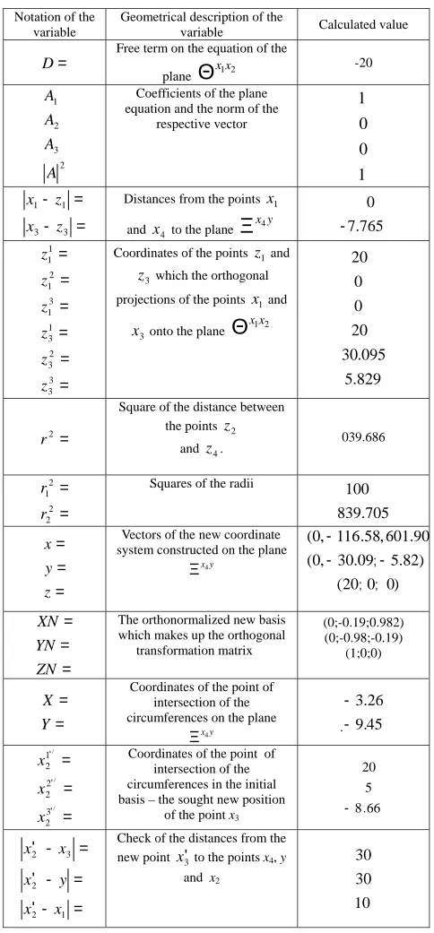
Table 3.1 presents the results of the solution of system (3.1). Note that since, as different from the problem with spherical joints, in this case the points x1 and x2 lie in the plane, the solution procedure becomes a little simpler.
j jx
x ′
Ξ Θxixi+1
j jx
x ′
Ξ
1 + Θxixi
0 1+ =
′
− D
x Ai in
∑
=
′ =
−
3
1
2 3 2 2) (
i
i i
l x y
∑
=
′ =
−
3
1
2 2 2 2 1 ) (
i
i i
l x x
2
Such a choice of coefficients is due to the fact that the rotation of the point x2 can take place only in the
1
plane x=20.
Table 1 Succession of Calculations for the Solution of System (1)
Notation of the variable
Geometrical description of the
variable Calculated value
=
D
Free term on the equation of the
plane Θx1x2
-20 2 3 2 1 A A A
A Coefficients of the plane
equation and the norm of the respective vector 1 0 0 1 = -= -3 3 1 1 z x z
x Distances from the points x1
and x4 to the plane
y x4 Ξ 7.765 0 -= = = = = = 3 3 2 3 1 3 3 1 2 1 1 1 z z z z z
z Coordinates of the points z1 and
z3 which the orthogonal
projections of the points x1 and
x3 onto the plane 2 x 1 x Θ 829 . 5 095 . 30 20 0 0 20 2 = r
Square of the distance between the points z2
and z4. 039.686
= = 2 2 2 1 r
r Squares of the radii
705 . 839 100 = = = z y
x system constructed on the plane Vectors of the new coordinate
y x4
Ξ
0; 0)
20 ( ) 82 . 5 ; 09 . 30 , 0 ( 90 . 601 , 58 . 116 , 0 ( -= = = ZN YN
XN The orthonormalized new basis
which makes up the orthogonal transformation matrix М
(0;-0.19;0.982) (0;-0.98;-0.19) (1;0;0) = = Y X
Coordinates of the point of intersection of the circumferences on the plane
y x4
Ξ . 9.45
26 . 3 -= = = ' ' ' / / / 3 2 2 2 1 2 x x
x Coordinates of the point of
intersection of the circumferences in the initial basis – the sought new position
of the point x3 8.66
5 20 -= -' = -' = -' 1 2 2 3 2 x x y x x
x Check of the distances from the
new point x3' to the points x4, y
and x2
10 30 30
;
As seen from Table 3.1, the found point x΄ (20,5,-8.66) lies in the 2 1
plane x = 20, which is what we wanted to establish.
Now we are to calculate the Euler angles for two rotations
x2 "x΄ and 2 x΄3 " y.
2. Rotation x2 "x΄ .2
a. We choose arbitrary values for the parameter α and calculate the values of the parameter β (Milnikov A.A., Prangishvili A.I., Rodonaia I.D. (2005))
b. we define the orthogonal matrix of the basic representation (Milnikov A.A., Prangishvili A.I., Rodonaia I.D. (2005))
from which, comparing the elements of the obtained matrix with Euler transformation matrix, we easily calculate the Euler angles
It is not difficult to verify whether our calculations are correct. For this, it is sufficient to substitute the calculated values of the Euler angles into transformation matrix and verify the fulfillment of the equality x΄ 2 =Ax2 .
3. Rotation x΄3 " y.
c. We define the displacement of the point x occurring during the 3 rotation
x2 "x΄ :2 .
718 . 10 ;
268 . 0 ;
1 ;
40 2 1 2
1 = α = β =− β =−
α
a
0.999
0.043
−
0.025
−
0.05
0.865
0.499 0
0.5
−
0.866
=
0 864
. 2 30
025 . 0 sin sin
0 sin sin
866 . 0 cos
/ /
0 0
/ = = =
− = = =
′ ′
′ xx xx xx xx
x x x
x ϕ ψ
θ
θ ψ
θ ϕ
θ
) 66 . 8 ; 35 ; 20 (
2 /
3 = −
ξ
d. We move the origin to the rotation center x΄2
Next we choose arbitrary values for the parameter α and calculate the values of the parameter β (Milnikov A.A., Prangishvili A.I., Rodonaia I.D. (2005)).
e. We define the orthogonal matrix of the basic representation (Milnikov A.A., Prangishvili A.I., Rodonaia I.D. (2005))
from which, comparing the elements of the obtained matrix with transformation matrix, we easily obtain the Euler angles
In this case, too, we can verify whether our calculations are correct through verifying the fulfillment of the equality y= αx΄ .3
Figure 2. The flow diagram of a manipulator with Rotational Pairs:
a) ___ Initial position; b) …… Terminal position.
We conclude this subsection by making two remarks.
Remark1: The use of the above approach to the solution of the inverse kinematic problem for a manipulator with rotational pairs requires that the rotation planes of manipulator joints be given explicitly. In our example the plane x = 20 is the given one, though, certainly, it can be chosen arbitrarily.
Remark2: It has more than once been noted that the nature of the spinor method allows us to work directly with Cartesian coordinates and use, in that case, a single coordinate system. The latter fact is an undoubted advantage as compared with the classical method which requires that data for manipulators be given in terms of rotation angles. The considered problem can be reformulated in terms of rotation angles as follows:
о 1
1. Rotate by 30 the second joint (x1 _ x2) in the plane x = 20;
о
2. Rotate by 15 the third joint (x2 _ x3) in the plane orthogonal to the second joint.
It is not difficult to solve the problem in such a formulation, but it is rather difficult to obtain the formulation in terms of rotation angles
proceeding from the formulation in terms of Cartesian coordinates. The latter is a separate problem which demands the development of special methods.
Conclusion
Earlier obtained results of spinor representation for generalized three-dimensional rotations to allowed to transform the statement of inverse task of kinematics: the spinor method's nature allows to work with Cartesian coordinates and use the only coordinate system which is the doubtless advantage comparing with the classical method, requiring to formulate tasks for manipulators in terms of angle rotations.
Such an approach allowed to develop the new method and two-stage algorithm of solution of the inverse kinematics task for multilink spatial mechanisms with rotational pairs.
At the first stage the coordinates of new positions of all joints are being determined, at the second stage the orthogonal matrix of the basic representation and the Euler angles are being calculated. A concrete example of Euler angle calculation for the multilink mechanism with rotational pairs is given.
References
1. Gelgamd I.M., Milnos R.A., Shapiro Z.A., (1972) Representations of Rotations Group and Lorentz Group, -425 p. Nauka, Moscow
2. Milnikov A., H. Onal, C. Erguven, I. Rodonaia., (2006) A Spinor Method Solution of Manipulators' inverse Kinematics of spatial rotations and Euler's Angles: Problems of Mechanics International scientific Journal, No 1(22), p. 41-48, Tbilisi
3. Milnikov A., Onal H., Partskhaladze R., Rodonaia I., (2004) Spinor evaluation of Euler's angles: Jornal of applied mechanics, No2, p.p. 48-53. Tbilisi
4. Milnikov A.A., Prangishvili A.I., Rodonaia I.D. (2005) Spinor Model of Generalized Three-dimensional Rotations: Automation and remote Control, Vol.66, No 6, p.p. 876-872, Moscow