Published online February 28, 2014 (http://www.sciencepublishinggroup.com/j/jeee) doi: 10.11648/j.jeee.20140201.12
Design of a photovoltaic system as an alternative source
of electrical energy for powering the lighting circuits for
premises in Ghana
Christian Kwaku Amuzuvi
*, Emmanuel Effah
University of Mines and Technology, Department of Electrical and Electronic Engineering, Tarkwa, Ghana
Email address:
[email protected] (C. K. Amuzuvi), [email protected] (C. K. Amuzuvi)
To cite this article:
Christian Kwaku Amuzuvi, Emmanuel Effah. Design of a Photovoltaic System as an Alternative Source of Electrical Energy for Powering the Lighting Circuits for Premises in Ghana. Journal of Electrical and Electronic Engineering. Vol. 2, No. 1, 2014, pp. 9-16.
doi: 10.11648/j.jeee.20140201.12
Abstract:
This paper seeks to emphasise the tendency of the use of solar energy as an alternative source of energy for today as far as the lighting needs of a particular infrastructure is concerned. It compares the use of a Photovoltaic (PV) System and an existing 60 kVA generator that powers a premise. The paper provides a general understanding of a solar energy (renewable energy) and how photovoltaic technology can be practically applied to power the lighting needs of the premise. Analysis of the site, weather data, and the design predicted the value of the photovoltaic system as an economic investment. We present the analysis undertaken using the PVSYST software package to optimize the system design for the premise. The simulation and calculation was done with the consideration of a PV array’s tilt and direction and economic considerations. The proposed photovoltaic system for the premise, with 30 units of battery capacity of 17850 Ah, an inverter size of 132 kW and a minimum number of 8 modules at 12.53 kWp was sufficient for the proposed design. The output analysis when implemented will result in a substantial lifetime energy savings, improving reliability and provide a great impact on the environment. It is therefore worthwhile to invest in photovoltaic renewable energy systems to augment the energy needs of locations where its use is viable.Keywords:
Standby Generator, Changeover, Automatic, Microcontroller, Switching, Firmware, Uninterruptible1. Introduction
Energy plays a pivotal role in our daily activities. For this reason, the degree of development and civilization of a country is measured by the amount of utilization of energy by it citizenry. Energy demand is increasing day in day out due to increase in population, urbanization and industrialization with its concomitant lifestyle. The world’s fossil fuel supply e.g. coal, petroleum and natural gas will thus be depleted in a few hundred years [1].
All forms of energy can be harnessed and stored in different ways. Energy sources are classified into two groups: renewable (an energy source that can be used over and over again) and non-renewable (the energy source that is used up and cannot be recreated in a short period of time) energy [2].
Renewable energy sources have been utilized by humankind since the beginning of civilization [3]. For centuries and in many ways, biomass has been used for heating, cooking, steam rising and power generation;
hydropower and wind energy for movement and later for electricity production [4]. As the rate of energy consumption increases, supply is depleting resulting in energy shortage. This has brought about what is called an energy crisis [5]. The need therefore for an energy mix through alternative or renewable sources of energy cannot be overemphasised in meeting future energy requirement.
Ghana has developed a Strategic National Energy Plan (2006-2020) [6]with issues concerning energy efficiency, electrification, elimination of power shortage and liberalisation of the power generation market, which will allow independent power producers to add their generated power to the national grid. The government proposes the addition of 10% of the energy need with renewable energy, where the average yearly growth for the total energy demand is 5% and the growth of electricity consumption is more than 10% [7].
clouds, oceans and land masses [8]. The spectrum of solar light at the Earth’s surface is mostly visible and near infrared ranges with a small part in the near-ultraviolet [9]. The total solar energy absorbed by the earth’s atmosphere, oceans and land masses is approximately 3,850,000 exajoules (eJ) per year [8]. The amount of solar energy reaching the surface of the planet is so vast that in one year, it is about twice as much as will ever be obtained from all of the earth’s non-renewable resources of coal, oil, natural gas etc. Solar energy can be harnessed at different levels around the world mostly depending on the distance from the equator [10].
2. Materials and Methods
Various types of renewable energy sources such as geothermal, ocean tides, wind and sun have geographical limitations, but solar energy has less geographical limitation as compared to other non-conventional energy sources because solar energy is available over the entire globe. It is the size of the collector field that needs to be increased to provide the same amount of heat or electricity. It is free, inexhaustible, non-polluting and devoid of political control.
2.1. Ways for Converting Solar Energy into Electrical Energy
There are two ways by which we can convert solar energy into electrical energy: by solar thermal or solar photovoltaic systems.
2.1.1. Solar Thermal
The solar collectors concentrate sunlight to heat a heat transfer fluid to a high temperature. The hot heat transfer fluid is then used to generate steam that drives the power conversion subsystem, producing electricity. Thermal energy storage provides heat for operation during periods without adequate sunshine. Figure 1 shows the solar thermal system for generating electrical energy.
Figure 1. Solar Thermal Energy System [9].
2.1.2. Solar Photovoltaic
Another way to generate electricity from solar energy is to use photovoltaic cells; magic slivers of silicon that converts the solar energy falling on them directly into electricity.
Figure 2 shows a typical solar photovoltaic plant.
Figure 2. Solar Photovoltaic Plant [9].
2.2. Photovoltaic System
Photovoltaic offer the ability to generate electricity in a clean, quiet and reliable way. Photovoltaic systems are comprised of photovoltaic cells and devices that convert light energy directly into electricity. Because the source of light is usually the sun, they are often called solar cells. The word photovoltaic comes from “photo” meaning light and “voltaic” which refers to producing electricity [2]. Photovoltaic is often referred to as PV.
2.2.1. Photovoltaic Cell
It is a device that produces an electric reaction to light, producing electricity. PV cells do not use the sun’s heat to produce electricity. They produce electricity directly when sunlight interacts with semiconductor materials in the PV cells [2]. A typical PV cell made of crystalline silicon is 12 centimeters in diameter and 0.25 millimeters thick. In full sunlight, it generates 4 amperes of direct current at 0.5 volts or 2 watts of electrical power [8].
2.2.2. Types of Photovoltaic Cells
There are essentially two types of PV technology; the thin-film type and the crystalline type. In the thin film type, the PV is made by depositing an ultra-thin layer of photovoltaic material onto a substrate. The most common type of thin-film PV is made from amorphous silicon, but numerous other materials such as copper indium/gallium dieseline (CIGS), copper indium selenite (CIS), Cadmium Teluride (CdTe), dye-sensitised cells and organic solar cells are also possible [8].
2.2.3. Photovoltaic Modules
PV cells are the basic building blocks of PV modules. For almost all applications, the one-half volt produced by a single cell is inadequate. Therefore, cells are connected together in series to increase the voltage. Several of these series strings of cells may be connected together in parallel to increase the current as well [11].
and metal. An outer frame is used to house the module to increase mechanical strength, and to provide a way to mount the unit. This package is called a module or panel. The amount of current produced is directly proportional to the cell’s size, conversion efficiency, and the intensity of light. For example, groups of 36 series connected PV cells are packaged together into standard modules that provide a nominal 12 volt (or 18 volts at peak power) [2].
2.2.4. Performance of a Photovoltaic Module
The performance of PV modules and arrays are generally rated according to their maximum DC power output (watts) under Standard Test Conditions (STC). STC are defined by a module (cell) operating temperature of 25°C (77°F), and incident solar irradiance level of 1000 W/m2 (sun’s insolation) and under air mass of 1.5 spectral distribution. Since these conditions are not always typical of how PV modules and arrays operate in the field, actual performance is usually 85 to 90% of the STC rating[12]. A photovoltaic module will produce its maximum current when there is essentially no resistance in the circuit. Figure 3 depicts a graph called an I-V (current-voltage) curve.
This would be a short circuit between its positive and negative terminals. This maximum current is called the short circuit current, abbreviated Isc which is the current when
voltage is zero. Conversely, the maximum voltage is produced when there is a break in the circuit. This is called the open circuit voltage, abbreviated Voc. Under this
condition the resistance is infinitely high and there is no current, since the circuit is incomplete [13].
These two extremes in load resistance, and the whole range of conditions in between them, are depicted on a graph called an I-V (current-voltage) curve. Current, expressed in amps, is on the vertical Y-axis. Voltage, in volts, is on the horizontal X-axis as shown in Figure 3. As seen in Figure 3, the short circuit current occurs on a point on the curve where the voltage is zero. The open circuit voltage occurs where the current is zero. The power available from a photovoltaic module at any point along the curve is expressed in watts. At both the short circuit current point and the open circuit voltage point, the power output is zero.
Figure 3. Standard V-I characteristic Curve of a PV Module [2].
There is a point on the knee of the curve where the maximum power output is located. This point on the
example curve is where the voltage is 17 volts, and the current is 2.5 amps. Therefore the maximum power in watts is 17 volts times 2.5 amps, equaling 42.5 watts.
The power, expressed in watts, at the maximum power point is described as peak, maximum, or ideal among other terms. The current-voltage (I-V) curve is primarily based on the module being under standard conditions of solar radiation and module temperature.
2.3. Photovoltaic Array
The desired power, voltage and current, can be obtained by connecting individual PV modules in series and parallel combinations in much the same way as batteries. When modules are fixed together in a single mount, they are called a panel and when two or more panels are used together, they are called an array as shown in Figure 4. Single panels are also called arrays. When circuits are wired in series (positive to negative), the voltage of each panel is added but the amperage remains the same. When circuits are wired in parallel (positive to positive, negative to negative), the voltage of each panel remains the same and the amperage of each panel is added. This wiring principle is used to build PV modules. PV modules can then be wired together to create PV arrays.
Figure 4. Cells, Modules and PV Arrays [9].
2.4. Types of Photovoltaic System
There are basically three types of photovoltaic systems. They include the grid connected PV system, stand-alone system and the hybrid system.
Figure 5. Grid Connected PV Systems [14].
2.4.1. Grid Connected PV Systems
a high quality inverter, which converts DC power from the solar array into AC power that conforms to the grid’s electrical requirements.
During the day, the solar electricity generated by the system is either used immediately or sold off to electricity supply companies. In the evening, when the system is unable to supply immediate power, electricity can be bought back from the network as shown in Figure 5.
2.4.2. Stand-Alone Systems
PV systems not connected to the electric utility grid are known as off grid PV Systems and also called stand-alone systems. Direct systems use the PV power immediately as it is produced, while battery storage systems can store energy to be used at a later time, either at night or during cloudy weather conditions. These systems are used in isolation of electricity grids, and may be used to power radio repeater stations, telephone booths and street lighting. Figure 6 shows a typical off grid PV systems.
Figure 6. Off Grid PV Systems [15].
Figure 7. Hybrid Power System [8].
2.4.3. Hybrid System
A hybrid system combines the PV with other forms of power generation usually a diesel generator. Biogas can also used.
The other form of power generation is usually a type, which is able to modulate the power output as a function of demand. However, more than one form of renewable energy may be used e.g. wind and solar [16]. The photovoltaic power generation serves to reduce the consumption of non-renewable fuel. Figure 7 shows a typical hybrid system.
2.5. Elements included in a System of Photovoltaic Conversion
The main elements that can be included in a system of
photovoltaic conversion are solar panels, batteries, regulators/controllers, invertors and load as summarized in the block diagram of Figure 8. For a reliable generation system that can function independent of the utility grid, batteries may be a viable component to the total system [14]. Back-up generators may be included in a system to provide power when the PV system is not operating, and are generally included when systems are not grid connected.
Figure 8. Block diagram of a PV system.
3. Results and Discussion
In order to ensure that there are no defects or inefficiency in the PV system which is usually caused by poor maintenance or ageing of its components [14], it is essential to collect accurate data for the long term performance analysis of the system. To achieve this, the solar radiation at the premise and the load data were collected and analysed.
Figure 9. Graph of Daily Solar Radiation and Ambient Temperature Records Summarized By Mean Monthly.
3.1. Solar Radiation at the Premise
temperature. The output result is used to directly compare with electricity bills paid monthly to the ECG.
3.2. Load Data
Eight (8) hours of operational time was chosen for each illuminant. The number of lamps in the various parts of the premise and the total energy consumption of each type of lamp were analysed. The total daily energy utilization of the premise for eight hours is 3348 Wh. With the load assessment detail in hand, the total Watt-hours per day needed from the PV modules was calculated by multiplying the daily energy utilized (DEU) per day by 1.3 (this is the standard energy lost in a PV system taking into account the wasted energy from wiring, charge controllers, batteries and inverters) to get the total Watt-hours per day which must be provided by the panels [17]. Therefore, 3348 Wh/day×1.3 = 43534.4 = 43.53 kWh/day.
Figure 10. The Proposed Circuit Design of the Photovoltaic System.
3.3. Materials Used
The materials employed for this design are categorized into software and PV hardware components. The PVSYST V5.0 software is a computer software package for the study, sizing and data analysis of complete PV systems. It deals with grid-connected, stand-alone, pumping and DC-grid PV systems, and includes extensive meteorological and PV systems components databases, as well as general solar energy tools.
It is designed to entail a contextual help which explains in details procedures and models used and offers an ergonomic
approach with a guide in the development of this paper providing results in the form of a full report, specific graphs and tables. Figure 10 shows the circuit diagram of the proposed PV design using the PVSYST V5.0 software.
The hardware components include; the PV modules, battery, charge controller, inverter, wires and cables and other safety and auxiliary components. The main purpose of a charge controller is to prevent the battery from being under- or overcharged.
The inverter is also used in the system where AC power output is needed. The input rating of the inverter should never be lower than the total wattage of the appliances to be used. The inverter must have the same nominal voltage as the battery with the size 25-30% bigger than the total watts of the appliances [18].
All inverters have a continuous rating and a surge rating. The surge rating is usually specified at so many watts for so many seconds. This means that the inverter will handle an overload of that many watts for a short period of time. This surge capacity will vary considerably between different types of inverters, even within the same brand. Generally, a 3 to 15 second surge rating is enough to cover 99% of all appliances.
The wires and cables used in this design must be in compliance with the National Electrical Code with color codes to designate its function and use. The conductor material was copper which is the most common with thermoplastic being the insulation material.
3.4. Sizing of Components and System Design
With the aid of the PVSYST V5.0, specifications, sizing and configurations of the major components with the exception of the invertor explained above were achieved.
3.4.1. Estimation of Electric Load on a Daily Basis
The first step required for gathering the energy load data is to find the overall amount of energy that the premise can store. This step also identifies opportunities for efficiency improvements and paves the way for sizing the system components. Equation 1 is used to compute the average number of watt hours required by the premise:
Day Used Hours Quantity Power
Day Wh
Average = × × (1)
The calculation and estimation of the required load on a daily basis for the premise is 43534.4 Wh/day or 43.53 kWh/day calculated earlier.
3.4.2. PV Module Sizing
Different size of PV modules will produce different amount of power. To determine the sizing of the PV module to use, the total watt-peak rating is needed which also depends on size of the PV module and the climate of site location. However, the module sizing was derived using the software. The total number of modules = 8 modules, with Isc
3.4.3. Battery Sizing
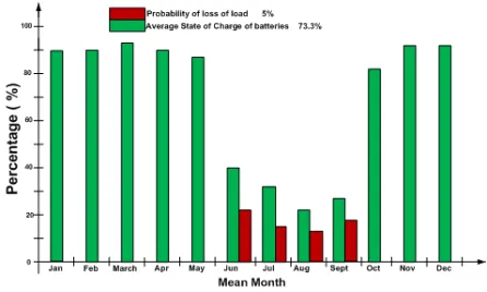
The batteries must be able to store the total daily load, in addition to the extra energy lost by inverting from DC to AC. With the help of the software, 30 batteries (6 in series × 5 in parallel) of a 12 V battery with capacity of 17850 Ah were required. These batteries will provide adequate storage to meet the daily energy requirements, operating temperature effects of 50°C, 4 days of autonomy, which is the number of days the battery sustains its charge with no sunshine to recharge it, and 5% of loss of load (LOL), which is the probability time fraction at which the battery is disconnected due to the “low charge” regulator security.
3.4.4. Controller Sizing
From standard practice, the sizing of the solar charge controller is to take the Isc of the PV module and multiply it
by a factor of 1.56 and the number of panels [19]. Therefore, 5.1 A × 1.56 × 8 = 63.65 A.
3.4.5. Inverter Sizing
In the sizing of the solar inverters, it should be noted that the inverter should be 25-30% bigger than the total Watts of all appliances that are to be powered by the system. It must also be able to handle the expected surge or in-rush of current that some large loads draw upon. The method for estimating surge requirements is simply to multiply the total AC watts by three at realistic conditions where household loads do not surge. The main criterion was to match the inverter’s input voltage with the nominal battery voltage and choosing the desired AC output voltage of 240 VAC. The total AC load is approximately 44 kW which must be the inverter size and therefore equal to the minimum inverter continuous watt rating. The minimum surge rating will be 44 kW × 3 = 132 kW.
3.5. Safety Regulations
This PV system complies with Health and Safety Requirements, BS 7671, and other relevant standards and Codes of Practice. The designed system had an effective grounding system to limit voltages due to lightning, power line surges and unintentional contact with higher voltage lines and also provide a current path for surplus electricity to travel to earth [19].
3.6. Proposed Design Output
The function of the proposed design is to provide an alternative source of electrical energy to power the lighting circuits of the premise. The design produced 8 modules at 12.53 kWp (peak kilowatt) at operating conditions and a battery capacity of 17850 Ah, thereby improving the reliability, adequacy, economic and environmental impacts. The PVSYST software provided comparisons of the light energy consumption data of the premise to the amount of energy that could be produced by the proposed photovoltaic system at solar radiation recorded monthly for the geographical area of the premise.
The graph in Figure 11 demonstrates the proposed design
output. The green bars in the graph represent the monthly energy demands of the premise with the red bars representing the amount of energy that can be produced by a 12.53 kWp system. It can clearly be seen that the design produces enough electricity to fully offset the lighting load of the premise. The energy demand is 43.55 kWh per day whereas the systems mean daily available output is 60.4 kWh per day. Excess energy is produced, except the month of June, July, August and September which produces relatively less energy in excess.
Figure 11. Graph Showing Available Solar Energy and User’s Needs by Mean Monthly Output of the Proposed PV System.
Figure 12 also shows the average state of charge of batteries and the probability of LOL by mean monthly. The state of charge of batteries is the actual capacity of the battery, which is defined at nominal current, but varies with the discharge current level and temperature. It was however, noted from the graph above that June, July, August and September had less probability of LOL.
Figure 12. Graph Showing Average State of Charge of Batteries and Probability of Loss of Load by Mean Monthly Output.
3.7. Economic Analysis
3.7.1. Life Cycle Cost for Proposed Design
The life cycle costs (LCC) are the sum of the equipment (initial) costs and operational costs arising during the project until the end of the project horizon, which is usually set between 20 and 30 years [15].
The equipment costs are the initial costs incurred at the beginning of the PV system electrification whilst the operational costs include the running costs, maintenance and replacement costs. Tables 1 and 2 below represents the initial and maintenance cost respectively for a period of 20 years and at a rate of 5%.
Table 1. Initial Installation Cost Analysis for the Proposed Photovoltaic System
PV Components Quantity Unit Price
(GH¢) Price (GH¢)
Solar PV Module 8 1,000.00 8,000.00
Battery 30 390.00 11,700.00
Inverter 1 6,504.70 6,504.70
Controller 1 3,000.00 3,000.00
Labour and Miscellaneous - - 10,000.00
Total Initial Cost (GH¢) 28,674.70
Table 2. Maintenance Cost Analysis for the Proposed Photovoltaic System
Maintenance Cost
Energy Cost (GH¢/hour) 1.78
Annuities and Maintenance (GH¢) for 20 years 14,460
Total Life Cycle Cost 43,134.70
3.8. Comparison between the Proposed PV Design and the 60 kVA Generator
Before the comparisons and projections were made, the life cycle cost of the 60 kVA generator was also obtained as indicated in Table 3. Table 4 also show the general comparison between the proposed design and the 60 kVA generator.
Table 3. General Comparison between Proposed Design and 60 kVA generator
Initial Cost Price (GHc)
Cost of generator 39,200
Installation Cost 11,478
Total Initial Cost 50,678
Annual Maintenance Cost
Servicing; GHc400 for every 3 months 1600
Diesel pricing; GHc162 for 90 litres full tank 1000
Total Annual Maintenance Cost 2600
Total Maintenance Cost for 20 years 52,000
Total Life Cycle Cost of Generator 103,356
Table 4. General Comparison between the Proposed Design and the 60 kVA generator
Factors Solar (PV) 60 kVA Generator Set
Resource Availabilit y
Sunlight readily
available Fuel is expensive and can be
scarce
Mode of
Operation Simple Complicated
Merits
Relatively Cheap Silent
Very long system lifespan
Reliable power all month provided fuel is available Generator not restricted to
lighting circuits alone but powers all load at the premise
LCC
Environm e-ntal and Social Impact
Relatively higher installation cost but low maintenance and operation cost No pollution
Low installation but high maintenance and operation cost
Air Pollution
Demerits
• Poor system output from June to September due poor sun exposure
• System was limited to lighting circuits
• Environmental and Noise pollution
• Relatively Simple installation
4. Conclusion and Recommendations
4.1. Conclusion
Ghana is endowed with solar and other renewable energy resources that can contribute immensely to residential and industrial energy needs for the country. This paper reveals the appropriateness of the generation of electric power using solar renewable energy compared to the use of a diesel generator. The proposed photovoltaic system for the premise required a 30 unit of battery capacity of 17850 Ah, an inverter size of 132 kW and a minimum number of 8 modules at 12.53 kWp for the design. The design achieved all the set goals relating to reliability, efficiency, adequacy, cost-effectiveness and environmental impact issues albeit limited to only the lighting circuits of the premise.
4.2. Recommendations
The following are recommended from the proposed design:
Hybrid system of renewable power generation should be considered to further improve the reliability, efficiency, adequacy, cost-effectiveness and environmental impact issues of electricity provision; The PVSYST software and other simulation programs should be used as a tool to assist individuals and other researchers in the optimization of the design of PV systems and
Acknowledgment
CKA thanks the University of Mines and Technology, Tarkwa, Ghana for their support. The authors are also grateful to Oklu Timothy, a graduate of UMaT from the Electrical and Electronic Engineering Department who took up the challenge to find an alternative source of electrical energy for the premise.
References
[1] Anon (2006), “Renewable Energy Potential in Africa” International Energy Agency (I.E.A.), Geneva, Switzerland, pp. 88.
[2] Singh, J. (2010), “Study and Design of Grid connected Solar PV system at Patiala,” Unpublished MSc Thesis Report, Thapia University, Patiala – India, 94pp.
[3] Attachie, J. C. and C. K. Amuzuvi (2013), Renewable Energy Technologies in Ghana: Opportunities and Threats. Research Journal of Applied Sciences, Engineering and Technology, 6(05): 776-782.
[4] Gritsevskyi, A. (2000), “Renewable vs. Non-renewable energy sources, forms and technologies”, Journal for International Recommendations for Energy Statistics (IRES), 8pp.
[5] Anon (1998), “About Photovoltaic”, www.eren.doe.gov. Accessed: March 11, 2012.
[6] Aryeetey, E. (2005), “Guide to Electric Power in Ghana”, Resource Center for Energy Economics and Regulation, University of Ghana, Accra, 67 pp.
[7] Amuzuvi, C. K. and J. C. Attachie (2013), Effective Power Management in Homes and Premises in Ghana. Research Journal of Applied Sciences, Engineering and Technology, 6(03): 354-360.
[8] Sauder, E. M. (2008), “Development of an appropriate Solar and Wind Hybrid Charging Station for Electric Vehicles in Developing Countries”, Unpublished MSc Thesis Report, Pennsylvania State University, USA, 81pp.
[9] Anon (2007), “How a Photovoltaic System Works: Florida Solar Energy”, Journal of Solar Energy Solution Paper, Vol. 92, SN287-861, University of Florida, USA, pp. 1-4. [10] Anon (2005), “The History of PV”, www.top-50
solar.de/solarcount.com.html. Accessed: March 3, 2012.
[11] Dunlop, H., Nilsen, Riisem, E., Skåre, D., Salomatova, O. (2006), “The History Highlight of Solar Cells, www.org.ntu.no/solarcells/pages/history.php.de/solarcount.c om.html, Accessed: December 5, 2012.
[12] Zeroual, A. (2011), “Solar Power Generation for Commercial Purposes”, International Journal on Solar Energy, Vol. 19, pp. 263-274.
[13] Al-Barquoni, S. (2010), “Re-Evaluation and Re-Design Stand-Alone PV Solar Lighting Projects in Gaza Strip, Palestine”, Unpublished MSc Thesis Report, Islamic University of Gaza-Palestine, 85pp.
[14] Lubin, B. T. (2012), “Effect of Component Failures on Financial Status of Grid-Connected Photovoltaic Systems”, Unpublished PhD. Thesis Report, University of Hartford, 197 pp.
[15] Omar, M. (2007), “Computer-Aided Design and Performance Evaluation of PV diesel Hybrid System”, Unpublished MSc Thesis Report, An-Najah University, Palestine, 117pp.
[16] Dradi, M. (2007), “Design and Techno-Economical Analysis of a Grid Connected with PV/Wind Hybrid System in Palestine (Atouf Village-Case study)”, Unpublished MSc Thesis Report, An-Najah University, Palestine, 117pp.
[17] Anon (2010), “Renewable Energy Potential - Country Report Ghana (RECIPES)”, Technical Report on Developing Renewables, Amsterdam, 29pp.
[18] Joe, X. (2007), “MPPT Inverters and Charge Controller Algorithms for Solar Tracker”, International Journal of Electrical & Electronics Engineering, IJMME-IJENS, Vol. 10 No. 1, pp. 13-18.
![Figure 2. Solar Photovoltaic Plant [9].](https://thumb-us.123doks.com/thumbv2/123dok_us/9873244.1974788/2.595.319.548.111.242/figure-solar-photovoltaic-plant.webp)
![Figure 4. Cells, Modules and PV Arrays [9].](https://thumb-us.123doks.com/thumbv2/123dok_us/9873244.1974788/3.595.317.547.587.693/figure-cells-modules-pv-arrays.webp)
![Figure 7. Hybrid Power System [8].](https://thumb-us.123doks.com/thumbv2/123dok_us/9873244.1974788/4.595.61.289.293.562/figure-hybrid-power-system.webp)