Available Online at www.ijpret.com 29
INTERNATIONAL JOURNAL OF PURE AND
APPLIED RESEARCH IN ENGINEERING AND
TECHNOLOGY
A PATH FOR HORIZING YOUR INNOVATIVE WORKDESIGN AND SIMULATION OF MULTIBAND MICROSTRIP PATCH ANTENNA FOR
WIRELESS 2 GHz TO 12 GHz BAND APPLICATIONS WITH MICROSTRIP EDGE
FEEDING TECHNIQUE
SARITA GAJRAJ1, KAPIL KUMAWAT2
1. M. Tech Student SBCET, Jaipur Rajasthan, India. 2. Asst. Prof., H.O.D, ECE Dept. SBCETJaipur Rajasthan, India
Accepted Date: 07/07/2015; Published Date: 01/08/2015
\
Abstract: - In recent years many studies are concentrated on multiband micro strip antenna structures for important purposes in wireless communication systems, medical imaging, and radar sensor resolution. In this paper, we printed a circular radiator patch on FR4 substrate material. The relative dielectric constant was 4.4, and the thickness of the material was 1.6 mm. The patch was fed by a transmission line feeder, and there was a gap between the patch and the ground plane. Antenna design is simulated on electromagnetic (EM) simulation software HFSS and anechoic chamber with a network analyzer was used during the experimental tests. The simulated and measured results demonstrated that the proposed antenna achieved a wide impedance bandwidth from 2.0 GHz to 12.0 GHz with a return loss of less than -10 dB. The proposed antenna is easy to integrate with microwave circuitry for low manufacturing cost. The antenna structure is flat, and its design is simple and straight forward.
Keywords: Patch antenna, partial ground plane, UWB antenna
Corresponding Author: MS. SARITA GAJRAJ
Access Online On:
www.ijpret.com
How to Cite This Article:
Available Online at www.ijpret.com 30 INTRODUCTION
The commercial use of the frequency band 2.0 to 12.0 GHz for radar, positioning and data transmission has been released by the Federal Communication Commission (FCC) in 2002 [1]. In these UWB antennas have enormous attention in both academia and industry for applications in wireless transmission systems [2]. Impulse-Ultra wideband (I-UWB) is a carrier less short range communications technology in which its transmission occupies a bandwidth of more than 20% of its center frequency (>500 MHz) [3].Wireless communication systems have developed rapidly in recent years, an antenna as a front component is required to have a wide band, good radiation performances and sometimes switchable ability [4].
From a systems point of view, the response of the antenna should cover the entire operating bandwidth, and the antenna should be non-responsive to signals outside the specified band [5]. UWB have wide applications in short range and high speed wireless systems, such as ground penetrating radars, medical imaging system, high data rate wireless local area networks (WLAN), communication systems for military and short pulse radars for automotive even or robotics. The antenna is one of the crucial components, which determine the performance of UWB system [6]. In the past, one serious limitation of the micro strip antenna was its narrow bandwidth characteristics, being 15 to 50% that of commonly used antenna elements such as dipoles, slots, and waveguides horns [7]. This limitation was successfully removed achieving a matching impedance bandwidth ratio it was necessary to increase the size, height, volume or feeding and matching techniques [8] Generally, UWB communication antennas require low voltage standing wave ratio (VSWR<2), constant phase center, constant group delay, and constant gain over entire operating frequency band [1].
I. Antenna Configuration And Design
For patch antenna the length and width are used as calculated from the equations. The expression for εreff is given by Balanis as [9]:
(1)
Available Online at www.ijpret.com 31
(2)
The effective length of the patch Leff now becomes:
Leff = L + 2 ΔL (3)
For a given resonance frequency fo, the effective length is given by
(4)
For a rectangular microstrip patch antenna, the resonance frequency for TMmn mode is given
by James and Hall as:
(5)
For efficient radiation, the width W is given by:
(6)
The motivation of UWB antenna is to design a small and simple antenna that introduces low distortions with large bandwidth. The geometry of the antenna is as shown in Figure 1.
Available Online at www.ijpret.com 32
II. Antenna Design
The micro strip-fed UWB antenna's radiating patch is spade-shaped. The antenna is designed on a substrate with thickness of 1.6 mm and relative permittivity of 4.4. A semicircle structure is adapted in the front side of radiating patch, which results in a smooth transition from one resonant mode to another and ensures good impedance match over a broad frequency range. Two rectangles are cut off from bottom patch separately, which improve the characteristic of the high frequency band. The half-wavelength of the lowest resonant frequency in UWB band (f
= 3.1 GHz) can be calculated with Expression (1).
(7)
Where, λp denotes the corresponding phase wavelength of the resonator; f represents frequency; r is the effective dielectric constant of the substrate; c is the speed of the light in free space.
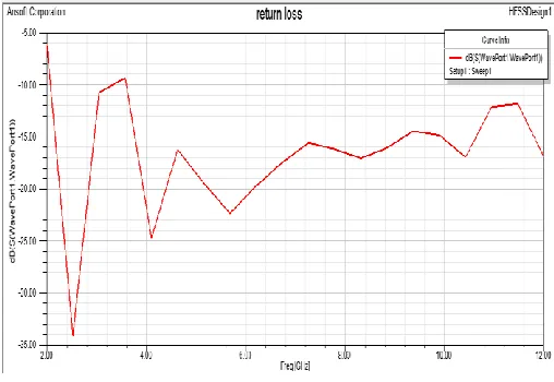
The simulated return loss of the multi band antenna is presented in Figure 2. The -10 dB impedance bandwidth is from 2.0 GHz to 12.0 GHz.
III. Simulation Results
The simulated results are obtained using Ansoft simulation software high-frequency structure simulator (HFSS) taking operating frequency 10GHz. The Six notch frequencies are obtaining at 2.4 GHz, 4.1GHz, 5.7GHz, 8.4GHz, 10.3GHz, and 12.0 GHz with -10dB return loss values shown in figure 2.
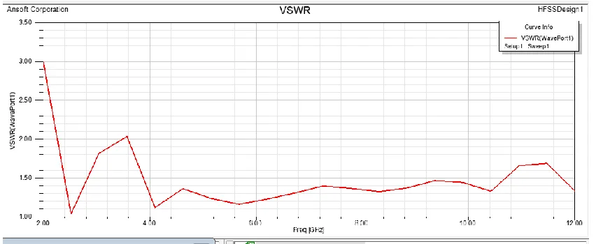
Available Online at www.ijpret.com 33 Figure 3 shows the VSWR curve for multi band monopole Patch Antenna. The value of VSWR is less than 2 of the entire band of 2 GHz to 12 GHz wireless range.
Figure 3: VSWR curve
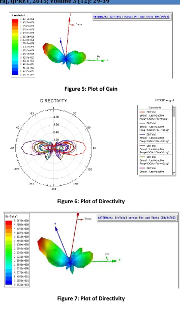
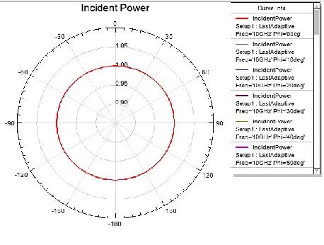
The other antenna parameters like gain, directivity, peak gain, and radiated gain, accepted power, incident power, and radiation efficiency, front to back ratio, E field and H field are also simulated in figure4, figure5, figure6, figure7, figure8, figure9, figure10, figure11, figure12, figure13, figure14, figure15 and figure16 respectively.
Available Online at www.ijpret.com 34 Figure 5: Plot of Gain
Figure 6: Plot of Directivity
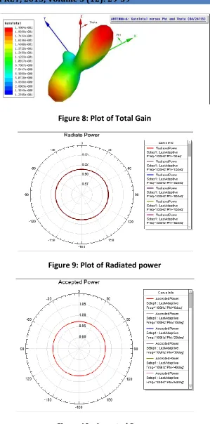
Available Online at www.ijpret.com 35 Figure 8: Plot of Total Gain
Figure 9: Plot of Radiated power
Available Online at www.ijpret.com 36 Figure 11: Plot of incident power
Figure 12: Radiation Efficiency
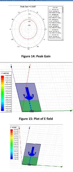
Available Online at www.ijpret.com 37 Figure 14: Peak Gain
Figure 15: Plot of E field
Available Online at www.ijpret.com 38 V. RESULT AND DISCUSSION
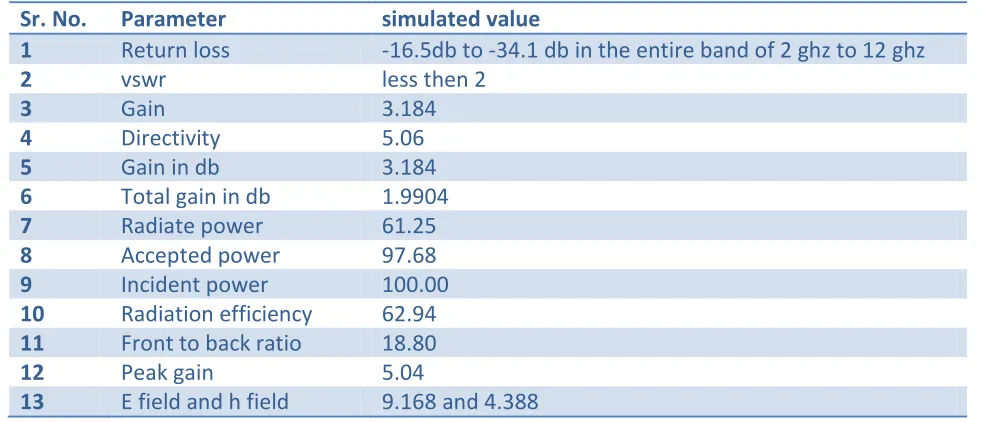
The various designing parameters like return loss, VSWR, gain, directivity, total gain, radiate power, acceptant power, incident power, radiation efficiency front to back ratio, peak gain, E-field and H-E-field are calculated with the help of simulation software. All the calculated values are shown in table 1.
TABLE 1 SUMMARIZED SIMULATED RESULTS
Sr. No. Parameter simulated value
1 Return loss -16.5db to -34.1 db in the entire band of 2 ghz to 12 ghz
2 vswr less then 2
3 Gain 3.184
4 Directivity 5.06
5 Gain in db 3.184
6 Total gain in db 1.9904
7 Radiate power 61.25
8 Accepted power 97.68
9 Incident power 100.00
10 Radiation efficiency 62.94
11 Front to back ratio 18.80
12 Peak gain 5.04
13 E field and h field 9.168 and 4.388
VII. CONCLUSION
In this paper, the radiation performance of a monopole multiband patch antenna designed on glass epoxy FR4substrate. The antenna is capable of providing enhanced bandwidth to cover Wi MAX, Wi Fi and Bluetooth operations at Absolute Bandwidth (GHz) Below -10 db is 2 GHz to 12 GHz allotted by IEEE 802.16 working group for Wi MAX and UWB applications.
Available Online at www.ijpret.com 39 REFERENCE:
1. Nuurul Hudaa M. Sobli and Hany E. Abd-El-Raouf “Design of a Compact Band-Notched Antenna for Ultrawideb and Communication” Antennas and Propagation Society International Symposium, 2008. 5-11 July 2008, pp. 1 – 4.
2. M. K. A. Rahim, M. N. A. Karim, T. Masri, A. Asrokin, "Comparison between Straight and U shape of Ultra Wide Band Microstrip Antenna using Log Periodic Technique" in IEEE International Conference on Ultra-Wideband 2007, 24-26 September 2007, pp. 696 - 699.
3. G. Brzezina, Q. Ye, L. Roy, "Development of a Practical Ultra-Wideband Antenna with Planar Circuit Integration Possibilities" in IEEE Antenna and Propogation Soc. Int. Symp.2005, 3-8 July 2005, pp. 504- 507.
4. G. Singh, M. Kumar “Design of frequency Reconfigurable Microstrip Patch Antenna”, 2011 6th IEEE International Conference on Industrial and Information Systems, ICIIS 2011, Aug. 2011, pp. 18-22.
5. M. Kumar, A. Basu, and S. K. Koul, “UWB Printed Slot antenna with improved performance in time and frequency domain,” in Progress In Electromagnetic Research C, Vol. 18, pp. 197-210, 2011.
6. Rezaul Azim, Ahmed Toaha Mobashsher, Mohammad TariqulIslam and Norbahiah Misran “Compact Planar Antenna for UWB Applications” in ICMMT 2010 Proceedings.
7. M. A. Peyrot Solis, G. M. Galvan-Tejada, H. Jardon-Aguilar, "State of the Art in Ultra-Wideband Antennas," in 2PndP International IEEE Conference on Electrical & Electronics and XI Conference on Electrical Engineering, 7-9 September 2005, pp. 101-105
8. R. Garg, P. Bhartia, I. Bahl, A. Ittipiboon, "Microstrip Antenna Design Handbook," Ed. Artech House, 2001, ch. 9, pp. 53