Computation of Stress Intensity Factor
in Functionally Graded Plates under Thermal Shock
Nazari, M.B.‒ Shariati, M.‒ Eslami, M.R. ‒ Hassani, B.
Mohammad Bagher Nazari1,* ‒ Mahmoud Shariati1 ‒ Mohammad Reza Eslami2 ‒ Behrooz Hassani1 1 Shahrood University of Technology, Iran
2 Amir-Kabir University of Technology, Iran
This paper addresses the implementation of the element-free Galerkin method, which is enriched intrinsically for fracture analysis of functionally graded materials under mode I steady-state and transient thermal loading. The stress intensity factors are evaluated by means of both equivalent domain integral and displacement correlation technique. Continuum functions and the micromechanical model are used to describe the distribution of material properties. For thermal shock analysis, the modal decomposition method, which is a semi-discretization approach, is implemented to obtain the transient temperature field. Also, few parametric analyses are performed to study the effect of material gradation on the stress intensity factors. The results imply that the magnitude of the stress intensity factor reaches its peak a short while after the thermal shock, indicating its significant role in the fracture failure.
©2011 Journal of Mechanical Engineering. All rights reserved.
Keywords: functionally graded materials, element-free Galerkin method, equivalent domain integral, displacement correlation technique, thermal stresses
0 INTRODUCTION
Functionally graded materials (FGMs) are a new type of advanced composites that are introduced for use in high temperature environments. The composition, microstructure and/or crystal structure of the FGMs change gradually, forming a non-homogeneous material with continuously varying thermomechanical properties. In recent years, FGMs have been used widely in other applications. According to the experimental studies of Kawasaki and Watanabe [1], when sudden cooling is applied to ceramic/ metal FGMs, some edge cracks are created on the ceramic surface. Therefore, examining the surface crack problem in FGMs under thermal loading,especially thermal shock, is important in failure analysis of these materials.
Jin and Noda [2] derived the general form of the thermoelastic crack-tip fields in FGMs. They assumed that the material properties are continuous and piecewise differentiable function of spatial position and some of them are not zero at the crack-tip. According to their study, the variation of material properties does not affect the order of singularity of thermoelastic crack-tip fields. Kishimoto et al. [3] showed that in the presence of thermal loading, the path independency of original J-integral is lost. They
not completely path-independent and results were unreliable for small integral domain size.
The EFG method provides an efficient and robust framework of analyzing fracture mechanics problems. This method has been implemented for fracture analysis of cracks in FGMs under mechanical loading e.g. [11] or steady-state thermal stresses [10]. In this paper, the EFG method is applied in both steady-state and transient thermal fracture of FGMs. The transient thermal loading is imposed in the form of thermal shock.
This paper is organized as follows. Section 1 presents the thermoelastic governing equations. Section 2 provides the EFG discretization form of governing equations. Section 3 explains the use of the equivalent domain integral for thermal fracture of FGMs. Section 4 describes the modal decomposition technique to obtain the transient temperature field. Section 5 presents the obtained numerical results of thermal SIF as well as parametric analyses and the relevant aspects of the results are discussed. Finally, in Section 6 conclusions are drawn.
1 GOVERNING EQUATIONS
A body occupying a space Ω surrounded by a surface Γ under external actions, body forces and prescribed thermal boundary conditions has been considered. The governing equations for static linear thermoelasticity in the domain Ω are:
∇ ⋅ + =σ b 0, (1a)
−∇ + = ∂ ∂
q Q c T
t
ρ . (1b)
Also, the heat flux is obtained based on the Fourier law:
q= − ∇k TI . (2) The constitutive equation is defined as:
σσ=C: (εε εε− th), (3) where,
εε = ∇su, (4a) εεth =α(T T− ) .
0 I (4b)
Here, the material properties are the forth-order Hooke tensor C, isotropic conductivity k, expansion coefficient α, density ρ and specific heat
c. The field variables are displacement u, strain tensor ε, stress tensor σ, and thermal strain εth and
the imposed values are heat source Q and body force b. Moreover, I is the identity second-order tensor and ∇s is the symmetric gradient operator on a vector field. The boundary conditions are as follows:
T T= on ΓT, (5a)
k TI∇ ⋅ =n q on Γq, (5b) k TI∇ ⋅ +n h T T( − ∞)=q on Γc, (5c)
u u= on Γu, (5d)
σ ⋅ =n t on Γt, (5e) where h is the convection coefficient and n is the outward unit vector which is normal to Γ.
2 ELEMENT-FREE GALERKIN METHOD IN THERMOELASTICITY
We implement the EFG method to solve governing partial differential equations (PDEs) of 2D thermoelastic problems. This method needs only a set of nodes to construct the discretized model. In EFG, using moving least square (MLS) approximation leads stability in function approximation and applying the Galerkin procedure leads to a stable and well-behaved system of discretized equations. Here, the EFG discretization in the space dimension only is used and the Kantorovitch semi-discretization process is followed. According to the EFG method, the final discrete equations can be obtained as:
C Tth+
(
Kth+K T Fth)
= th+Fthγ γ , (6a)
K K U F F+
(
γ)
= + γ, (6b)where the dot (.) denotes differentiation with respect to time and:
Cijth
i j
c d
=
∫
ρ φ φ ΩΩ , (7a)
Kijth kB BithT thj d h i jd c
=
∫
Ω+∫
ΓΩ Γ φ φ , (7b)
Fith
i i i
Q d q d h d
q c
=
∫
φ Ω+∫
φ Γ+∫
θ φ∞ ΓΩ Γ Γ , (7c)
Fγthi γ θφid T
=
∫
Γwhere:
Bith i
i x x = ∂ ∂ ∂ ∂ φ
φ 12 , (7e)
and
Kij =
∫
ΩDB BiT jdΩ, (8a)Kij Ti S j
u
d
γ =γ
∫
ϕϕ ϕϕ ΓΓ , (8b)
Fi b iT t
iT
d d
t
=
∫
ϕϕ Ω+∫
ϕϕ ΓΩ Γ , (8c)
Fi Su di u
γ =γ
∫
ϕϕ ΓΓ , (8d)
where
S= = S S S u u
i i u
i u 1 2 0 0 1 0
, if given on ,
if not given on Γ
Γ (8e)
Bi i i
i i x x x x = ∂ ∂ ∂ ∂ ∂ ∂ ∂ ∂ φ φ φ φ 1 2 2 1 0
0 , (8f)
ϕϕi i i = ϕ ϕ 0
0 . (8g)
In the enriched EFG method, the singularity problems due to the presence of a crack is alleviated by enrichment functions. In the intrinsic enrichment, the standard basis (usually polynomials) vector is enriched by including the near-tip asymptotic displacement field [12]:
p xT x x r r
r r
( ) , , , cos , sin ,
sin sin , cos sin
= 1 2 2 2 2
1 2 θ θ
θ θ θ θ
, (9)
where r and θ are the usual crack-tip polar coordinates.
3 EQUIVALENT DOMAIN INTEGRAL FOR THERMAL FRACTURE
The J-integral is an energy-based method which is widely used to calculate SIFs. The
J-integral originally was derived in the form of a contour integral [13]:
J W j ij iu n dj A A
=
∫
( δ1 −σ ,1) Γ ,Γ (10)
where ΓA is an arbitrary contour enclosing the
crack-tip and nj is the jth component of the
outward unit vector normal to ΓA. For the sake
of simplyfying the calculation, it is suitable to convert this contour form into an equivalent domain integral. Defining a smooth weight function q and applying the divergence theorem, the equivalent domain form of the J-integral is derived as [7]:
J=
∫
A( uσij i,1−Wδ1j)q dA,j +∫
A(W,1)explqdA, (11)where A is the area inside the contour ΓA. The first
integral contains W,1, i.e., the partial derivatives of W with respect to x1. It should be noted that in FGMs the temperature field and material properties are dependent on spatial coordinates. In linear elastic fracture mechanics, J-integral is equal to the energy release rate and the relationship between the energy release rate and the mode I SIF is given by:
J K E= I2 tip* , (12)
where Etip* =Etip for plane stress and E
tip (1−νtip2 ) for plane strain. Etip and νtip are Young's modulus
and Poisson's ratio, respectively, evaluated at the crack-tip.
4 TRANSIENT HEAT CONDUCTION PROBLEM
To obtain the temperature field, the first-order matrix differential equation (6a) should be solved. Among many methods, the modal decomposition technique [14] was chosen. Modal decomposition is an analytical approach to solve systems of ordinary differential equations (ODEs) without the introduction of additional approximations. Based on the modal decomposition procedure, a coupled system of ODEs is turned into uncoupled equations by using eigenvectors. The complete solution of Eq. (6a) can be expressed as a linear combination of all eigenvectors of the system
T(t) = [T1, T2, ..., TN]ψ(t) = Mψ(t), where M is
an N×N square matrix whose columns are the eigenvectors. Substituting the above definition into Eq. (6a) and premultiplying it by MT, the
uncoupled system of equation is obtained, Cth*ψψ+Kth*ψψ =M FT( th+Fth),
where
Kth* = MT · Kth · M, (14a) Cth* = MT · Cth · M. (14b)
The system of Eq. (13) contains N uncoupled equations,
ψi i iψ i ii
s i N
+ = ΛΛ =
C* ,( 1 2, ,..., ), (15)
where si =Kiith*/Ciith* and Λ = MT(Fth+ Fγth). The initial condition ψ (0) can be obtained from
T(0) = M· ψ(0). Depending on the complexity of the right-hand side of Eq. (15), it is solved either analytically or numerically.
5 NUMERICAL RESULTS AND DISSCUSSION
In this section, the calculation of the mode I SIF for an edge crack in functionally graded plate (FGP) under thermal stresses is considered. In addition, a few parametric analyses are performed to study the effect of the gradation of material properties on the stress intensity factor. The distribution of material properties is determined by means of continuum functions e.g., exponential function or micromechanics models e.g., self-consistent model. Examples are presented here: • An edge cracked plate: exponential gradation. • FGP with an edge crack: power law gradation. • Edge crack in an FGP: micromechanics
model.
The FGP of length W and height H with a crack of length a, as depicted in Fig. 1a, is considered. The thickness (in the x3 direction) of the plate is assumed to be quite thin for plane stress analysis and large enough for plane strain analysis. The crack is aligned parallel to the direction of material property gradation. Initially, the FGP is at a uniform stress-free temperature T0. Temperatures of x1 = 0 and x1 = W faces are decreased to constant temperatures T1 and T2, respectively. All other faces, including the crack surfaces, are assumed to be insulated, which results in a dimensional heat conduction problem in the x1 direction. In all cases, the calculated SIFs will be normalized by dividing to:
K0 =E( ) ( )0α 0T0 πa (1−ν( )).0 (16)
5.1. An Edge Cracked Plate with Exponentially Gradation
Fig. 1a shows an unconstrained FGP with an edge crack of length a, Fig. 1b presents the complete node arrangement of the FGP which consists of 1695 regular nodes and 40 crack-tip nodes, with a total of 1735. Fig. 1c shows the crack-tip node arrangement. In this case, two different types of functionally graded materials are considered with exponentially varying thermomechanical properties (E, ν, α, k, ρc), in the
x1 direction, e.g.:
E x( )1 =E( )exp(0 P xE 1), (17) where the nonhomogeniety parameters are defined e.g., as:
P W
E W E
E =
1
0 ln ( )
( ) . (18)
Fig. 1. An FGM plate with an edge crack; a) geometry, b) complete node arrangement, c)
crack-tip node arrangement
The values of the nonhomogeneity parameters for the first material are selected arbitrarily (academic materials) as they follow to provide conditions for which the references solutions are available.
E(0) = k(0) = α(0) = ρc(0) = 1.0, ν(0) = 0.3.
For the sake of comparison, two different cases of the thermal boundary conditions are considered in the steady-state analysis. In the third case, a transient analysis is also carried out for different temperatures at the left and right sides of the plate.
In order to verify the implementation of DCT and EDI approaches in the framework of EFG method, comparisons of the calculated SIFs and the available reference solutions are first presented. In this case, the temperature of x1 = 0 and x1 = W faces are decreased from T0 to T1 and
T2, respectively. Table 2 compares the normalized SIFs with the results provided by Erdogan and Wu [4], KC and Kim [8] and Yildirim [6]. The obtained solutions are in good agreement with the references. It is interesting to note that our model is comprised of 1735 nodes, while the 2D mesh discretization in KC and Kim [8] consists of 966 elements and 2937 nodes in the framework of the finite element method.
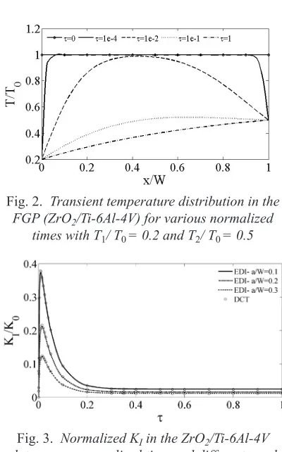
Since the surface crack is usually created during cooling, the FGP problem subjected to a cooling shock is considered here. To consider the thermal shock, it is assumed that the FGP is initially at a uniform stress-free temperature T0 and suddenly cooled down to constant temperatures
T1 = 0.2 T0 and T2 = 0.5 T0 at the left and right hand side faces, respectively. The obtained results for the transient temperature distribution in the ZrO2/Ti-6Al-4V FGM versus normalized time τ, as defined in Eq. (19), is depicted in Fig. 2.
τ= k ρ c
W t
( ) ( ) ( ) .0 0 0
2 (19)
According to these results, the temperature gradient near the plate edges is considerably large at the early times after imposing the thermal shock.
Figs. 3 and 4 present normalized SIFs in the ZrO2/Ti-6Al-4V plate resulting from the transient temperature field versus the normalized time τ and the normalized crack length a/W for plane strain and plane stress cases, respectively. As shown in these figures, the SIF quickly increases to a peak value that is drastically larger than the steady value and then decreases rapidly to the corresponding steady value for all crack lengths. In addition, the magnitude of SIF decreases as the normalized crack length a/W becomes larger in both transient and steady states that are in agreement with the results that have recently been reported by Noda and Guo [5].
Table 1. Material properties of ZrO2 and Ti-6Al-4V
Materials modulus Young's [GPa]
Poisson's ratio
Coefficient of thermal expansion [10-6 /K]
Thermal conductivity
[W/(m K)]
Mass density
[kg/m3] Specific heat [J/(kg K)]
ZrO2 151.0 0.33 10.0 2.09 5331 456.7
Ti-6Al-4V 116.7 0.33 9.5 7.5 4420 537.0
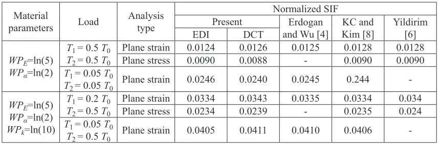
Table 2. Normalized mode I SIF in FGP under steady-state thermal loading
Material
parameters Load Analysis type
Normalized SIF
Present Erdogan
and Wu [4] KC and Kim [8] Yildirim [6]
EDI DCT
WPE=ln(5) WPα=ln(2)
T1 = 0.5 T0
T2 = 0.5 T0
Plane strain 0.0124 0.0126 0.0125 0.0128 0.0128
Plane stress 0.0090 0.0088 - 0.0090 0.0090
T1 = 0.05 T0
T2 = 0.05 T0 Plane strain 0.0246 0.0240 0.0245 0.244
-WPE=ln(5) WPα=ln(2) WPk=ln(10)
T1 = 0.2 T0
T2 = 0.5 T0
Plane strain 0.0334 0.0343 0.0335 0.0334 0.034
Plane stress 0.0234 0.0239 - 0.0235 0.024
T1 = 0.05 T0
-Fig. 2. Transient temperature distribution in the FGP (ZrO2/Ti-6Al-4V) for various normalized
times with T1/ T0 = 0.2 and T2/ T0 = 0.5
Fig. 3. Normalized KI in the ZrO2/Ti-6Al-4V plate versus normalized time and different crack
lengths in plane strain condition
As the final point, the magnitude of SIF for the plane strain is larger than plane stress. Noda et al. [14] have derived thermal stresses analytically for a homogeneous isotropic strip under one-dimensional transient temperature distribution. These results indicate that the thermal stresses for the plane strain case are equal to those of the plane stress multiplied by a factor of 1/(1-ν). Regarding the fact 0 < ν < 0.5, this factor is greater than one, which implies a larger SIF for the plane strain in comparison to the plane stress problem, which can be noticed from Figs. 2 and 3.
5.2. FGP with an Edge Crack with Power Law Gradation
A Ni/TiC plate with the configuration of the first example is considered here and a power-law function is assumed to describe the material properties in the x1-direction e.g., as follows.
E x( ) E( ) ( ( )E W E( ))( / ) .x W p
1 = 0 + − 0 1 (20)
The exponent p is a positive constant used as an adjusting parameter to obtain certain distribution for material properties. As the exponent p can be chosen independently from the comprised materials, this function is significantly flexible and hence widely used in practice for the analysis of the FGMs. In the proportional
material properties, the exponent p is assumed the same value for all material properties while it can be selected differently for non-proportional
materials.
Fig. 4. Normalized KI in the ZrO2/Ti-6Al-4V plate versus normalized time for different crack lengths
in plane stress condition
Moreover, here different thermal boundary conditions are imposed on the uncracked face of FGP. To apply a thermal shock, the cracked face is assumed to be quenched to a constant temperature of T1 = 0 while having the free convection at the other face with a convection coefficient of
h=10 W/(m2K) and the ambient temperature is assumed T0. The transient temperature distribution in the Ni/TiC plate is presented in Fig. 5 for the proportional case with p = 5. The effect of the convection boundary condition at the x1 = W face on the temperature distribution is more apparent at the steady-state. Figs. 6 and 7 show the transient thermal SIF versus crack lengths for the proportional case with p = 5 and p = 0.2, respectively. As can be seen, the variation of the thermal SIF is completely different for these cases. In the ceramic-riched case (p = 5), at the beginning of the thermal shock the SIF increases to a peak value and declines to its minimum quickly and then increase gradually to a steady-state value.
corresponding time of the crack closure increases as the crack length is increased. In this example, the crack closure occurred in steady-state for all crack lengths.
Fig. 5. Transient temperature distribution in the FGP (Ni/TiC) for various normalized times with
T1 = 0 and h = 10
Fig. 6. Normalized KI in the Ni/TiC plate versus normalized time and different crack lengths in
plane strain condition and p = 5
The effect of the thermal boundary condition applied on the uncracked face for the linear proportional material i.e., p = 1, is illustrated in the Fig. 8. Here, the h = 0 corresponds to the insulated thermal boundary condition and h = ∞ corresponds to a known temperature boundary
condition. According to these results, while the value of the SIF is independent of the type of the thermal boundary condition applied on the uncracked face, the steady-state value is completely dependent. Moreover, a greater value for the steady-state SIF is obtained for the case of constant temperature at both faces.
Fig. 7. Normalized KI in the Ni/TiC plate versus normalized time for different crack lengths in
plane strain condition and p = 0.2
Fig. 8. The effect of thermal boundary condition at x1 = W on the variation of normalized KI
Now, the effect of the material gradation is studied and some parametric analyses are carried out to assess their effect on the SIFs. In all cases, it is assumed that the exponent p gets different values for the special property and Table 3. Material properties of Ni and TiC
Materials modulusYoung’s [GPa]
Poisson’s ratio
Coefficient of thermal expansion
[10-6 /K]
Thermal conductivity
[W/(m K)]
Mass density
[kg/m3] Specific heat[J/(kg K)]
TiC 320 0.195 7.4 25.1 4940 134
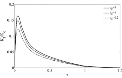
p = 0.2 for other material properties. Figs. 9 and 10 present the effect of variation in FGP elastic properties, i.e. Young’s modulus and Poisson’s ratio, on the SIF for the crack length a/W = 0.3 and the plane strain problem. According to Fig. 9, the magnitude of SIF, especially its peak value, increases significantly as the parameter pE is
increased. These results indicate that for all values of pE, the peak and the crack closure time occur
roughly simultaneously. This can be explained by the fact that the transient temperature distribution is independent of the variations of the parameter
pE. We believe that the effect of Young’s modulus
is responsible for the slight difference between the peak time and the steady time.
The influence of Poisson’s ratio gradation on the SIF is shown in Fig. 10. It can be seen that, by a decrease in pν, i.e. for metal-riched whose
greater Poisson’s ratio, the magnitude of SIF and the crack closure time increase.
The analytical solutions for thermal stress distribution in an uncracked FGP under one-dimensional temperature distribution for the plane strain and plane stress cases are given as [4]:
σ
ν α ν
x x
th E x C x C x T x t
2 2
1
2 1 1 2 1 1
1 1
=
−
(
+ − +)
( ) ( )( )∆ ( , ) , (21a)
and
σx xth E x C x C α x T x t
2 2 = ( )1
(
1 1+ 2− ( )1 ∆ ( , ) ,1)
(21b)respectively, where C1 and C2 are unknown coefficients determined from the force and moment boundary conditions in the x2 direction. From Eq. (21), it is observed that the thermal stresses are an increasing function of Young’s modulus.
Fig. 9. Normalized KI versus normalized time for different pE; plane strain with a/W = 0.3, p = 0.2
for other material properties
The effects of the gradation of the thermal properties on the SIF during the shock period are shown in Figs. 11, 12 and 13. Fig. 11 depicts the normalized SIF versus normalized time for various values of the exponent p for the thermal expansion coefficient, i.e., pα. According to this figure, the
peak value of SIF for the case p = 0.2 is significantly greater than others. Also, depending on the pα
value, the trend of SIF might be completely different. For example, the crack is closed for the
pα = 0.2 and pα = 1 cases, while the SIF for pα = 5
increases gradually to a steady-state value after it peaks and reduces to a local minimum.
Fig. 10. Normalized KI versus normalized time for different pν; plane strain with a/W = 0.3,
p = 0.2 for other material properties
Fig. 11. Normalized KI versus normalized time for different pα values; plane strain with a/W = 0.3, p = 0.2 for other material properties
Fig. 12 illustrates the SIF variation in terms of time for various values of conductivity parameter pk. It can be seen that an increase of the
parameter pk causes a delay in the occurrence of
the peak value of SIF and steady-state. This delay is not surprising since the diffusivity k/ρc is an increasing function of the conductivity and the
with greater conductivity, Moreover, for ceramic-riched case (pk = 5) the peak value of SIF and the
crack closure time is greater than the metal-riched case. The variation of SIF with the normalized time and the nonhomogeniety parameter of ρc is presented in Fig. 13. These results indicate that the peak value of SIF is almost independent from pρc.
The peak time and the crack closure time increase for the ceramic-riched case (pρc = 5).
Fig. 12. Normalized KI versus normalized time for different pk. Plane strain with a/W = 0.3,
p = 0.2 for other material properties
Fig. 13. Normalized KI versus normalized time for different pρc values; plane strain with a/W = 0.3, p = 0.2 for other material properties
5.3 Edge Crack in an FGP with Micromechanics Model
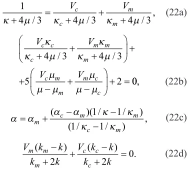
Prediction of the effective macroscopic properties is one of the basic issues in composite material theory. For FGMs, as the graded composites, some micromechanics models of composites have been developed. Among many micromechanics models extended for FGMs, self-consistent method (SCM) was used. Zuiker [16] has pointed out that the SCM provides a simple and initial estimate of effective properties which is
a benefit for relate optimal property distributions. Moreover, in this method the properties are determined independently of the phase of the inclusion and the matrix. This is significant for FGMs in which the volume fraction of the constituent phases varies in a wide range. For two-phase FGMs, the volume fraction of the ceramic is assumed in the form of a power function, i.e.
Vc = 1‒(x1/L)p, in which L is the material gradation length and the exponent p is known as the gradient index. Here x1 = 0 corresponds to pure matrix phase (ceramic) and x1 = L to pure inclusion material (metal). For a two-phase composite, the effective materials are determined from [16],
1
4 3 4 3 4 3
κ+ µ/ =κ + µ/ +κ + µ/ ,
Vc V
c
m
m (22a)
V V
V V
c c c
m m m
c m m
m c c
κ κ µ
κ κ µ µ
µ µ
µ µ µ
+ + +
+
+
− + −
+ =
4 3 4 3
5 2
/ /
00, (22b)
α α α α κ κ
κ κ
= + − −
−
m c m m
c m
( )( / / )
( / / ) ,
1 1
1 1 (22c)
V k k
k k
V k k
k k
m m m
c c c
( − ) ( ) .
+ + − + =
2 2 0 (22d)
We consider an edge crack in an unconstrained FGP of length W and height H = 8
W. To consider the thermal shock, it is assumed that only the cracked face of the FGP is suddenly cooled down to constant temperature T1 = 0 from the stress-free temperature T0. Fig. 14 presents the transient temperature distribution in the FGP. Here, it is assumed that ΔT = T(x1,t) ‒ T0.
Fig. 15. Normalized mode I stress intensity factor in the FGP versus normalized time and different
crack lengths in plane strain condition
Fig. 15 depicts the transient thermal SIF versus normalized crack lengths a/W for plane strain case. Although the steady value of SIF is greater for longer cracks, the peak value of SIF is significantly large for short cracks.
6 CONCLUSION
In this paper, the domain form of J-integral (EDI) and displacement correlation technique (DCT) in conjunction with element-free Galerkin method are implemented to evaluate the mode I stress intensity factor in FGMs under steady-state and transient temperature fields. The present study points out that:
1. In the enriched EFG framework a relatively coarse mesh in compared with FEM and common XFEM is sufficient for analysis of cracks in FGMs under thermal loading. 2. A short while after the thermal shock, SIF
increases to a large peak value, which is significantly greater than the corresponding steady value and then decreases rapidly to a steady value. Moreover, although the crack is closed at steady state for some cases, the value of SIF might reach to a large positive value during the thermal shock period. These imply that in thermal fracture analysis of FGMs, the SIF at the beginning of thermal loading might be the main factor in fracture failure analysis.
3. Parametric analyses indicate that the variation in the thermomechanical properties, especially thermal characteristics, has a significantly influence on the fracture behaviour of FGMs.
4. Comparison of the obtained numerical results with the reference solutions indicates that both energy-based EDI and direct approach DCT methods, in the framework of enriched EFG, are efficient tools to analyze the thermal fracture of FGMs.
7 REFERENCES
[1] Kawasaki, A., Watanabe, R. (2002). Thermal fracture behavior of metal/ceramic functionally graded materials. Engineering Fracture Mechanics, vol. 69, p. 1713-1728. [2] Jin, Z-H., Noda, N. (1994). Crack-tip singular
fields in nonhomogeneous materials. Journal of Applied Mechanics, Transactions ASME, vol. 61, p. 738-740.
[3] Kishimoto, K., Aoki, S., Sakata, M. (1980). On the path independent J-integral.
Engineering Fracture Mechanics, vol. 13, p. 841-850.
[4] Erdogan, F., Wu, B.H. (1996). Crack problems in FGM layers under thermal stresses. Journal of Thermal Stresses, vol. 19, p. 237-265.
[5] Noda, N., Guo, L.C. (2008). Thermal shock analysis for a functionally graded plate with a surface crack. Acta Mechanica, vol. 195, p. 157-166.
[6] Yildirim, B. (2006). An equivalent domain integral method for fracture analysis of functionally graded materials under thermal stresses. Journal of Thermal Stresses, vol. 29, p. 371-397.
[7] Dag, S. (2006). Thermal fracture analysis of orthotropic functionally graded materials using an equivalent domain integral approach.
Engineering Fracture Mechanics, vol. 73, p. 2802-2828.
[8] KC, A., Kim, J.H. (2008). Interaction integrals for thermal fracture of functionally graded materials. Engineering Fracture Mechanics, vol. 75, p. 2542-2565.
[9] Kim, J.H., KC, A. (2008). A Generalized interaction integral method for the evaluation of the T-stress in orthotropic functionally graded materials under thermal loading.
[10] Chen, J. (2005). Determination of thermal stress intensity factors for an interface crack in a graded orthotropic coating-substrate structure. International Journal of Fracture, vol. 133, p. 303-328.
[11] Rao, B.N., Rahman, S. (2003). Mesh-free analysis of cracks in isotropic functionally graded materials. Engineering Fracture Mechanics, vol. 70, p. 1-27.
[12] Fleming, M., Chu, Y.A., Moran, B., Belytschko, T. (1997). Enriched element-free galerkin methods for crack tip fields.
International Journal for Numerical Methods in Engineering, vol. 40, p. 1483-1504.
[13] Rice, J.R. (1968). A path independent integral and the approximate analysis of strain concentration by notches and cracks. Journal of Applied Mechanics, vol. 35, p. 379-386. [14] Zienkiewics, O.C., Taylor, R.L. (2000).
The Finite Element Method. Butterworth-Heinemann, Oxford.
[15] Noda, N., Hetnarski, R.B., Tanigawa, Y. (2003). Thermal Stresses. Taylor and Francis, New York.
[16] Zuiker, J.R. (1995). Functionally graded materials: choice of micromechanics model and limitations in property variation.