Volume 3, Special Issue 1, ICSTSD 2016
674
Performance Analysis of Field Oriented Controller
Based Brushless DC Motor Drive
Pragati K. Sharma
M-Tech Scholar,Electrical Engineering Department, Government College of Engineering,
Amravati (MS), India [email protected]
Anil S. Sindekar
Assistant Professor and Head, Electrical Engineering Department, Government College of Engineering,Amravati (MS), India [email protected]
Abstract: Brushless DC (BLDC) motors are gaining attention
from various commercial and household machine manufactures because of its high efficiency, high torque, high power density, low inertia, less noise, almost no maintenance, salient operation, compact form and reliability. The performance and reliability of Brushless DC motor drivers has improved by replacing the conventional control and sensing techniques with sensorless technology. In this paper, a robust sensorless field oriented controller (FOC) scheme for a Brushless DC motor has been proposed. To evaluate both position and speed, without any mechanical sensors from voltage and current measurements, a back-EMF-based high order sliding mode controller is designed which reduces the chattering phenomena. The stability of system can be evaluated by using Lyapunov theory. The effectiveness of the proposed estimation method using MATLAB/Simulink model has been demonstrated.
Keywords—Brushless DC motor, sensorless technology, Field
oriented controller, Sliding mode observer,
INTRODUCTION
BLDC motor is similar in construction as that of Permanent Magnet Synchronous Machine (PMSM). The main difference between PMSM and BLDC motor is stator winding construction. PMSM has sinusoidal flux density, current and back EMF (electromotive force) deviation whereas the BLDC has rectangular shaped flux density, current and back EMF deviation [1]. BLDC motor do not have both brushes and commutator, therefore its commutation is completely electronic and operation is more complex [2].For controlling a motor, it is essential to know the position of the rotor. Rotor position sensors such as hall-effect sensors, optical encoders and revolvers are needed to sense the position of the rotor. They are used to generate a constant torque by controlling the stator current. However, these position sensors make the motor expensive and mechanically unreliable. The methods to determine the speed and rotor position of the motor by measuring only their voltages and currents have evolved significantly in recent years. These methods are usually designated as sensorless, e.g. Sliding-mode Observer, Extended Kalman Filter, Artificial Neural Networks and Model Reference Adaptive System, etc. [3]. This paper uses sliding mode observer for estimating position and speed of the motor to achieve sensorless control [4-9]. This paper deals
with two popular and powerful method of control in electrical drive applications and these are field oriented control (FOC) and space vector modulation (SVM). SVM is a special switching sequence used in the three-phase power inverter. It generates lower harmonic distortions in the output voltages and currents applied to each phase of an AC motor and thus providing efficient use of supply voltage [10-12].
SENSORLESS CONTROL
The sensorless approach has several advantages:
More compact drive compared to other motor drive Absence of connecting wires
Cost of position-encoding device is neglected Increases mechanical strength
Suitable for hostile environments Low maintenance
FIELD ORIENTED CONTROL
Field oriented control (FOC) of PMSM is one of the broadly used methods for speed control of motors. This control is characterized by a smooth rotation over the entire speed range of motor, full torque control at zero speed, fast accelerations and decelerations. The basic idea of the FOC algorithm is to decompose stator current into a magnetic field-generating part and a torque-field-generating part. Both the components can be controlled separately after decomposition even at low speed and less noise level. By using FOC the structure of the motor controller has become as similar as that of separately excited DC motor. FOC has advantages such as it transforms a complex and coupled AC model into a simple linear system. It has good transient and steady state performance, fast dynamic response, high torque, high efficiency and low current at starting, Wide speed range through field weakening.
To perform FOC or vector control, it is necessary to follow these steps:
Estimate the motor quantities, phase voltages and currents
Using a Clarke transformation, transform them into the two-phase system
Volume 3, Special Issue 1, ICSTSD 2016
675 Using a Park transformation, transform stator currents
into the d, q reference frame
The torque (isq) and flux (isd) producing components of stator current are controlled independently
The output stator voltage space vector is evaluated using the decoupling block
The stator voltage space vector is then transformed back from the d, q reference frame into the two-phase system by an inverse Park transformation fixed with the stator
By using space vector modulation, the output three-phase voltage is generated
SLIDINGMODEOBSERVER
Sliding mode observer (SMO) is a technique with multiple advantages like order reduction, disturbance rejection, independence of system parameter. Therefore, it has become very popular for designing of robust system. The high frequency switching produced by SMO may cause chattering effect. As a solution for this problem, second-order sliding mode has been adopted, also called High Order Sliding Mode (HOSM). This HOSM control strategy can attain excellent control with no chattering problem. The stability of system can be analyzed by using Lyapunov theory.
MATHEMATICAL MODELLING OF
SLIDING MODE CONTROLLER
Followings assumptions are made in modeling of the BLDC motor
Saturation is neglected although it can be considered if parameter changes
Induced EMF is sinusoidal
Eddy currents and hysteresis losses are negligible There are no field current dynamics
There is no cage on the rotor
Fig1. Equivalent circuit of BLDC motor
Using Kirchhoff's voltage law,
…. (1)
The purpose of using the sliding mode observer (SMO) is to find position of the rotor with its permanent magnet flux
which is not certain, it can be estimated from the BEMF (back electromotive force)
…. (2)
The BEMF cannot be directly measured. An estimation from an observer is needed. SMO estimates the BEMF using a system model with voltage and current vector inputs. It is a type of feedback observer. Feedback is provided through the sign (signum) function. Signum function is defined as for real inputs, output -1 for negative input, +1 for positive input, and 0 for 0 input.
The state equations of PMSM under the static coordinate
system (α, β) is given by
.… (3)
Where,
current on α, β axis under α, β coordinate system; uα,uβ = voltage on α,β axis under α,β coordinate system; eα, eβ = counter-electromotive force on α, β axis under α, β coordinate system;
.… (4)
L=phase inductance;
R =phase resistance of the motor.
According to theory of slide-mode variable structure, the stator current is selected as state variable. The PMSM slide-mode observer of the construction is:
.… (5)
Where,
Estimated current on α, β axis under α, β coordinate system;
Ksw=slide-mode coefficient; sign( )=switching function
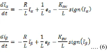
The dynamic error of the current is Equation (5) minus Equation (3) respectively:
Volume 3, Special Issue 1, ICSTSD 2016
676
.… (6)
Where, the value provided with ‘ ’ above it is the difference between the observing value of the variable and the actual value. Select the slide hyperplane S1 established on the customized current error as:
.… (7) Where,
,
.… (8)
Define the Lyapunov function and its derivative according to Equation (7). The slide-mode observer is under the slide mode status.
.… (9)
i.e.
.… (10)
Substitute Equation (6) into the above equation to attain the following:
..… (11)
Therefore, the range of value taken for Ksw satisfying Equation (6) may be derived as:
…..(12)
If it satisfies Equation (12), the slide-mode motion may be generated. The error dynamic equation (6) is asymptotically stable and the error is converged as zero according to exponential law. Therefore, the observing Equation (5) is also converged. According to Equation (12), the switch gain must be large enough to meet the above mentioned conditions. However, excessively large K can increase the buffeting noise, causing unnecessary estimated error. Therefore, the self-adaption rate is selected as:
...(13)
Where, =appropriate proportion constant. The determined by Equation (13) can satisfy Equation (12). When the status point reaches the slide mode switching plane with S1 = 0, the system starts the slide mode motion. The error dynamic equation performance is fully determined by the slide mode motion. Here:
….. (14)
Substitute Equation (12) into the error dynamic Equation (4) to attain:
... (15)
The switching signal of current error and contain information of EMF. To attain the smooth and continuous estimated EMF value through filtering by a low-pass filter with a certain cutoff frequency.
... (16)
Attain the estimated value of the rotor angle according to the estimated EMF value.
...(17)
However, the low-pass filter can cause delayed phase. Taking the estimated EMF value as example, the phase delayed angle is
.… (18)
Therefore, the estimated position value of the rotor needs to be compensated to a certain extent. For a low-pass filter with fixed cutoff frequency, the instantaneous value of compensation is:
… … … (19)
MATLAB/SIMULINKRESULTS
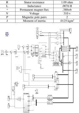
The simulation model of sensorless field-oriented controller is established. The main simulation model of the system is shown as in figure 2. The specifications of BLDC motor are as shown in table I.
TABLE I. PARAMETERS OF BLDC
Symbol Quantity Expressed in SI
Volume 3, Special Issue 1, ICSTSD 2016
677
R Stator resistance 1.09 ohm
L Inductance .0076 H
ᵠ Permanent magnet flux .388wb
V Voltage 310 v
P Magnetic pole pairs 2
J Moment of inertia .0125 kgm2
Fig 2. MATLAB/Simulink Model of Sensorless BLDC Motor Drive
Fig 3. Obtained speed waveform of BLDC motor
Fig 4. Obtained torque waveform of BLDC motor
Fig 5. Obtained rotor angle waveform of BLDC motor
From the result as shown in figure 3 we can say that proposed BLDC drive nearly catches the reference speed and get desired variation according to reference command. In figure 4 actual torque is given although there are change in the actual torque of the motor is near to given value. Figure 5 shows the error of the real and estimated rotor position. As it is shown the estimated rotor position settles quickly to its real value providing good tracking performance.
CONCLUSION
A sensorless robust control of a brushless DC motor has been presented. The sensorless scheme is achieved via a high order sliding mode observer that estimates the speed and the rotor position of motor. A Simulink model of BLDC motor and the proposed sliding mode observer is constructed. Simulation results show that speed and position estimation are accurate and the system is robust.
REFERANCES
Volume 3, Special Issue 1, ICSTSD 2016
678
[2] Jyoti Agrawal, Sanjay Bodkhe, “Sensorless permanent magnet synchronous motor drive : a review,” National Conference on Inovative Paradigms in Engineering & Technology (NCIPET-2013) Proceedings published by International Journal of Computer Applications (IJCA)
[3] Jose Carlos Gamazo-Real , Ernesto Vazquez-Sanchez, Jaime Gomez-Gil, “Position and speed control of brushless dc motors using sensorless techniques and application trends,” sensors ISSN 1424-8220, 19 July 2010
[4] Changsheng,LI Malik Elbuluk, “A sliding mode observer for sensorless control of permanent magnet synchronous motors,” 2001 IEEE
[5] Eduardo Quintero-Manríquez,Ramón A. Félix, “Second-order sliding mode speed controller with anti-windup for bldc motors,” World Automation Congress 2014
[6] Dafa Shi, “Sensorless control method of pmsm based on slide-mode observer,” 2012 IEEE Symposium on Electrical & Electronics Engineering (EEESYM)
[7] Uma Gupta, “Research on permanent magnet BLDC for small electric vehicle”, IEEE International Conference on Mechatronics and Automation August, Harbin, China 5 - 8, 2007
[8] Rev. 0, “Sensorless PMSM vector control with a sliding mode observer for compressors using MC56F8013” Freescale Semiconductor October 2008
[9] Marwa Ezzat, Alain Glumineau, Franck Plestan, “Sensorless high order sliding mode control of permanent magnet synchronous motor”, 2010 11th International Workshop on Variable Structure Systems Mexico City, Mexico, June 26 - 28, 2010
[10] P.Ramana, B.Santhosh Kumar, Dr.K.Alice Mary, “Comparison of various PWM techniques for field oriented control VSI fed PMSM drive”, International Journal of Advanced Research in Electrical, Electronics and Instrumentation Engineering Vol. 2, Issue 7, July 2013
[11] M. Sertug Basar, Michael M,Peter Scavenius, “Comparison of sensorless foc and SVM-DTFC,” 4th International Conference on Power Engineering, Energy and Electrical Drives Istanbul, Turkey, 13-17 May 2013
[12] M. B. B. Sharifian, T. Herizchi, K. G. Firouzjah, “Field oriented control of permanent magnet synchronous motor using predictive space vector modulation,” 2009 IEEE Symposium on Industrial Electronics and Applications (ISIEA 2009), October 4-6, 2009, Kuala Lumpur, Malaysia