www.adv-radio-sci.net/11/87/2013/ doi:10.5194/ars-11-87-2013
© Author(s) 2013. CC Attribution 3.0 License.
Radio Science
Improving the performance of BICM-ID and MLC systems with
different FEC codes
T. Arafa, W. Sauer-Greff, and R. Urbansky
University of Kaiserslautern, Communications Engineering, Gottlieb-Daimler-Str., 67653 Kaiserslautern, Germany
Correspondence to: T. Arafa ([email protected])
Abstract. In bandwidth limited communication systems, the high data rate transmission with performance close to ca-pacity limits is achieved by applying multilevel modulation schemes in association with powerful forward error correc-tion (FEC) coding, i.e. coded modulacorrec-tion systems. The most important practical approaches to coded modulation systems are multilevel coding with multistage decoding (MLC/MSD) and bit interleaved coded modulation with iterative demap-ping and decoding (BICM-ID).
Multilevel modulation formats such asM-QAM, which can be used as a part of coded modulation systems, have the capability of multilevel protection. Based on this fact, we in-vestigate the methods to improve the performance of BICM-ID using multiple interleavers with different binary channel coding schemes such as convolutional codes, turbo codes and low-density parity-check (LDPC) codes. Moreover, an MLC system with parallel decoding on levels (PDL) at the receiver is considered. In our contribution, we propose to de-sign the individual coding schemes using the extrinsic infor-mation transfer (EXIT) charts for individual bit levels in the constellation. Our simulation results show that the BICM-ID systems, taking into account different bit-level protections, can provide an improvement of 0.65 dB, 1.2 dB and 1.5 dB for 256-QAM with turbo, LDPC and convolutional codes, respectively. On the other hand, MLC systems with PDL de-signed using EXIT charts for individual bit levels can slightly improve the performance and eliminate the error floor com-pared to the systems with MSD.
1 Introduction
The increasing demand to achieve higher data rates in digi-tal communication systems with limited spectrum resources leads to employing multilevel modulation formats. In order to approach the channel capacity, an appropriate forward
er-ror correction (FEC) code is highly required to protect the multilevel signaling schemes. The combination of high level modulation schemes with FEC coding schemes is denoted as a coded modulation system.
The field of coded modulation was first introduced by (Massey, 1974) who proposed to jointly design cod-ing and modulation. Ungerboeck presented a practical ap-proach for coded modulation known as trellis coded mod-ulation (TCM) (Ungerboeck and Csajka, 1976; Ungerboeck, 1982). In this system, Ungerboeck proposed the set partition-ing strategy for mapppartition-ing scheme in order to maximize the minimum intra-subset Euclidean distance. The key point of this system is to deal with the free Euclidean distance mea-sure instead of the Hamming distance as in classical coding schemes. Therefore, the modulation and the channel coding based on convolutional code are combined in a single en-tity which enables to transmit only constrained sequences of symbols that maximize the minimum free Euclidean dis-tance.
low-density parity-check (LDPC) codes can be used in MLC systems.
A bit interleaved coded modulation with iterative demap-ping and decoding (BICM-ID) was proposed by (ten Brink et al., 1998; ten Brink, 1999) as an attractive technique to achieve both high spectral efficiency and high performance. Unlike MLC systems, BICM-ID systems use only one chan-nel encoder separated from modulation by an interleaver which achieve a reasonable complexity.
The task of mapping in high order modulation schemes such asM-QAM is to assign a number of bits to one sym-bol of the constellation points. The most important charac-teristic of these schemes is the constellation capacity. How-ever, each bit position has a distinct capacity, i.e. a different amount of protection. In this paper, we investigate the meth-ods to improve the performance of BICM-ID using the idea of protection matching with different binary channel coding schemes such as convolutional codes, turbo codes and LDPC codes. Moreover, an MLC system employing Gray mapping for modulation and parallel decoding on levels (PDL) at the receiver is considered. We proposed to design the proper in-dividual coding schemes with code rates using the extrinsic information transfer (EXIT) charts for individual bit levels in the constellation.
The remainder of this paper is organized as follows. The basic BICM-ID systems and the new design based on multi-level protection is briefly introduced in Sect. 2. The concept of MLC/MSD systems with an idea of code design is pre-sented in Sect. 3. The proposed code design based on EXIT charts for MLC/PDL systems is explained in Sect. 4. Simu-lation results and discussions are provided in Sect. 5. Finally, conclusions are drawn in Sect. 6.
2 BICM-ID systems
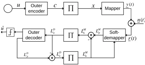
The BICM-ID system is a serial concatenation of channel encoding, bit-interleaving and multilevel modulations at the transmitter, while the turbo principle is adapted to iterative soft-demapping together with channel decoding at the re-ceiver (ten Brink et al., 1998). The performance mainly de-pends on matching between mapping and coding schemes. Therefore, a Gray mapping scheme should be combined with a strong channel code such as a serial or parallel concatenated convolutional code (turbo code) and an LDPC code. On the other hand, a mapping different from Gray mapping should be combined with a weak channel code. This system achieves more flexibility and simplicity from an implementation point of view than the other coded modulation systems.
The basic structure of the BICM-ID system is depicted in Fig. 1. At the transmitter, the sequenceu of k data bits is firstly encoded into a codeword c of n bits. The gener-ated codeword cis randomly interleaved by a bit-wise in-terleaver. After interleaving,mconsecutive bits are mapped onto one complex symbol ofM=2maccording to a mapping
Outer
encoder
Mapperu
x
Soft-demapper
Outerdecoder
1
) (t n
) (t y
) (t r
M a L
D a
L
-D p
L
M p
L
-M e L
D e L
c
uˆ
Fig. 1. Block diagram for conventional BICM-ID systems.
scheme. The originated complex symbolsyare corrupted by noise through the AWGN channel, so the received symbols arer=y+nwherenis a complex circular symmetric Gaus-sian noise with zero mean and varianceNo/2 in each
dimen-sion. At the receiver, and based on channel observationsr and a-priori information of unmapped bitsLMa (at first iter-ationLMa =0), the soft-demapper calculates the a-posteriori log-likelihood ratio (LLR) for each of themcoded bits per symbol by using (ten Brink et al., 1998)
LMp(xk|r)=LMa (xk)
+ln
P
y∈χk1
exp[−|r−y| 2
No +
m P
j=1,j6=k
µ−j1(y)LMa (xj)]
P
y∈χk0
exp[−|r−y| 2
No +
m P
j=1,j6=k
µ−j1(y)LM a (xj)]
, (1)
whereµ−j1(y)gives thej-th bit of the symbolywhileχk1,χk0 are the sets of symbols having the k-th bit set to 1 and 0, respectively. Then, the extrinsic information of the soft-demapper LMe =LMp −LMa is deinterleaved to become the a-priori inputLDa to the outer soft-in/soft-out decoder, which gives the a-posteriori valueLDp based on the BCJR algorithm (Hagenauer, 1997). The extrinsic information of the outer de-coderLDe =LDp −LDa is passed through the interleaver and fed back as a-priori informationLMa to the soft-demapper for the next iteration.
0 0.1 0.2 0.3 0.4 0.5 0.6 0.7 0.8 0.9 1 0 0.1 0.2 0.3 0.4 0.5 0.6 0.7 0.8 0.9 1 I A M "a−priori information" IE
M "extrinsic information"
I E M (x
1)=IE M (x
5) IE M (x
2)=IE M (x
6) IE M (x
3)=IE M (x
7) IE M (x
4)=IE M (x
8)
Fig. 2. EXIT curves of the individual bits in Gray 256-QAM map-ping for AWGN channel atEb/N o=7.5 dB. The first and fifth bits (x1and x5) have identical EXIT functions and similarly (x2 and
x6), (x3andx7), and (x4andx8).
irregular LDPC codes as a part of BICM-ID system, other considerations should be taken into account for protection matching. The LDPC code ensembles are defined by degree distributions(λ(x), ρ(x))≡
wv P
i=1
λixi−1, wc P
i=1
ρixi−1
of the variable nodes (VN) and check nodes (CN) withλi(resp.ρi)
being the fraction of edges connected to degree-i variable (resp. check) nodes. The LDPC code can be considered as a serial concatenation of outer repetition codes at the variable node, edge interleaver and inner parity check codes at the check node. Therefore, the degree of a variable node is equal to the number of repetitions. It is well known that more repe-titions, i.e. larger variable node degree, lead to more reliable decoded bit. Based on this explanation, the performance of BICM-ID systems with LDPC codes can be improved by as-signing the more reliable LDPC code bits always to the more protected bits in the constellation (Li and Ryan, 2005).
Figure 3 shows the block digram of BICM-ID transmitter with multiple interleavers and matching unit. This unit as-signs the coded and interleaved bits to different bit positions in theM-QAM symbol.
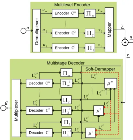
3 Multilevel coding and multistage decoding
The structure of an MLC/MSD system is depicted in Fig. 4. In the MLC transmitter, a sequence ofk information bits is partitioned intomsub-blocks of lengthki. Each partitioning levelihas its own encoderCi with code rateRi =ki/ni and is independently encoded and interleaved by a different in-terleaver5iwhere we assume the same block lengthnat all
levels. The overall rate of the MLC system results from the sum of the rates of the component codes. Every channel cod-ing concept is applicable. In this contribution binary LDPC
1 x m x 2 c 1 c 1 1 m 2 m S/P M a p p e r 3 4 3 c 4 c m c 1 m c info bits /
parity bits /
y Outer Encoder u c 1 s 2 s 3 s 4 s m s 1 m s 2 x M a tc h in g U n it
VNs with larger degree
VNs with smaller degree
Fig. 3. Block diagram of BICM-ID transmitter with protection matching. n r u 1 m 2 x 1 x m x M a p p e r 2 u 1 u m u y Encoder Cm
Encoder C1 Encoder C2
2
Decoder Cm
Decoder C1 Decoder C2
1 m 2 1 2 1 1 1 m m C e L 1 C e L 2 C e L 2 e Lμ 1 e Lμ m μ e L 2 1 m 2 a L 1 a L 1 a Lm
3 a L m a L Soft-Demapper M u lt ip le x e r D e m u lt ip le x e r Multilevel Encoder uˆ Multistage Decoder 2 a L
Fig. 4. Multilevel coding scheme with multistage decoder.
codes are used. Then, one bit from each coded and inter-leaved level is grouped to the sequence x= {x1, x2, ..., xm},
xi ∈ {0,1}, which is mapped to one of the M=2m signal
points of the set A. Set partitioning strategy as proposed by Ungerboeck is applied to maximize the minimum intra-subset Euclidean distance, see Fig. 5 for the case of 8-ASK (Ungerboeck, 1982).
The signal set A in the first step of set partitioning at level i=1 is divided into the subsets A(x1=0)and A(x1=1).
Then, all subsets A(x1. . . xi)at partitioning level i are
A
A(0) A(1)
A(00) A(01) A(10) A(11)
A(000) A(001) A(010) A(011) A(100) A(101) A(110) A(111)
0 1
x x11
1 2
x
0 2
x
0 3
x x31
1 2
x
0 2
x
0 3
x x31 x30 x31 x30 x31
Fig. 5. Ungerboeck set partitioning for 8-ASK.
A(x1. . . xi1)at partitioning level i+1. The iteration stops
when each subset at levelmcontains only one signal point. At MSD receiver, the soft-demapper firstly calculates the reliability information of the bits at level 1 with no a-priori information about the bits at the other levels Lµi
a =0, i=
2, . . . , m. The codesCi at the lowest leveli=1 can be de-coded using soft information that was passed from the soft-demapper. At the next stage, the soft-demapper uses soft in-formation that was passed from decoder C1 as a-prior in-formation for the bits at level 1 to calculate the reliability information of the bits at level 2 that will be passed to the decoderC2. This procedure is carried out until the last code is decoded. The MSD structure is suboptimum because the decoders of lower levels are not provided with any informa-tion of the decoders of higher levels and error propagainforma-tion may arise. Therefore, in some cases it is useful to iterate the decoding process with output information of higher levels, i.e. iterative MSD.
It was proved that MLC together with MSD can achieve the channel capacity at high spectral efficiency if the indi-vidual coding schemes with proper code rates are selected appropriately. The concept of designing the codes depends on the mutual information of the channelI (Y;R)between the transmitted signal points y∈A and the received sym-bolsr(Wachsmann et al., 1999). Using uppercase letters for the corresponding random variables, the mutual information of the channel inputy is calculated with the bijective map-ping according toI ((X1, X2, . . . , Xm);R)=I (Y;R)which is equal to the discrete channel capacity C. By using the chain rule of mutual information
I (Y;R)=I ((X1, X2, . . . , Xm);R)
=I (X1;R)+I (X2;R|X1)+. . .
+I (Xm;R|X1, X2, . . . , Xm−1), (2) we can separate the transmission of the address vectors x[k] over the physical channel into parallel transmissions of individual components xi[k] over equivalent channels,
whereas the knowledge about the less significant components x1[k], x1[k], . . . , xi[k] is a premise at the receiver. These
equivalent channels are directly correspond to the individ-ual levels in MLC as well as to the requirement of error-free decoding of the lower levels in the MSD. So, the components
n
r u
M
a
p
p
e
r
y Encoder Cm
Encoder C1
Encoder C2
D
e
m
u
lt
ip
le
x
e
r
Multilevel Encoder
Decoder Cm
Decoder C1
Decoder C2
M
u
lt
ip
le
x
e
r
uˆ
Parallel Independent Decoder
S
o
ft
-D
e
m
a
p
p
e
r
m C
e L
1 C e L
2 C e L
1
m
2
1 2
1 1
1
m
2 e Lμ
1 e
Lμ
m μ
e L
1
m
2
x
1
x
m
x
2
2
u
1
u
m
u
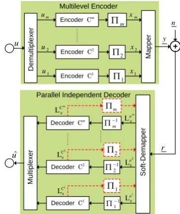
Fig. 6. Multilevel coding scheme with parallel decoder of the indi-vidual levels.
of the Eq. (2) are the capacitiesCiof the equivalent channels, where the capacity of levelicomputes to
Ci=I (Xi;R|X1, X2, . . . , Xi−1)
=I (Xi, . . . , Xm;R|X1, . . . , Xi−1)
−I (Xi+1, . . . , Xm;R|X1, X2, . . . , Xi). (3) When MLC is decoded with MSD, the total channel capacity C can only be obtained if the code rateRi at each level is equal to the capacity of the equivalent channelRi ≡Ci. This rate design method is called capacity rule.
4 Multilevel coding and parallel decoding on levels
4 5 6 7 8 9 10 11 12 13 14 15 10−6
10−5 10−4 10−3 10−2 10−1 100
Eb/No, dB
Bit Error Rate
Original Design New Design
16−QAM
64−QAM 256−QAM
Fig. 7. BER of BICM-ID with a rate-1/2 convolutional code for AWGN channel after 5 iterations.
of the equivalent channeliwith PDL is
Ci=I (Xi;R). (4)
The PDL capacity highly depends on the particular mapping. Gray mapping scheme can achieve a good performance for MLC/PDL systems. Therefore, we propose to use a strong FEC codes such as capacity-approaching LDPC codes. The individual code rates are designed using the EXIT charts for individual bit levels.
The soft-demapper EXIT curve can be estimated for a spe-cific channel SNR by Monte-Carlo simulation where the a-priori LLR values can be assumed to be Gaussian distributed. This function can be expressed as
IEM(x)=TM(IAM(x), Eb/No)
= 1
m
m X
i=1
TiM(IAM(x), Eb/No), (5)
whereTM is the EXIT function of the soft-demapper and
{IEM(xi)=TiM(IAM(x), Eb/No)}is the EXIT function for the
different bits,i=1,2, . . . , m.
Based on the average EXIT function and bit-level EXIT functions, the individual code rates are designed as follow-ing. We construct the average EXIT function of mapping at a certain SNR, where the area under curve is
A=C
m. (6)
Then, the area under each bit-level EXIT curve isAi=Ci, i=1,2, . . . , m. Therefore, the code rate at each level isRi≡
Ci.
3 3.5 4 4.5 5 5.5 6 6.5 7 7.5 8 8.5
10−6 10−5 10−4 10−3 10−2 10−1 100
Eb/No, dB
Bit Error Rate
Original Design New Design 64−QAM
256−QAM 16−QAM
Fig. 8. BER of BICM-ID with a rate-1/2 turbo code for AWGN channel after 10 super iterations.
2.5 3 3.5 4 4.5 5 5.5 6 6.5 7 7.5 8 8.5 9
10−6 10−5 10−4 10−3 10−2 10−1 100
Eb/No, dB
Bit Error Rate
Original Design New Design
16−QAM 64−QAM
256−QAM
Fig. 9. BER of BICM-ID with a rate-1/2 LDPC code for AWGN channel after 10 super iterations.
5 Simulation results
In the following simulations we compare the performance of new BICM-ID design based on multilevel protection of high order modulation schemes versus basic design for dif-ferent FEC coding schemes. Moreover, we introduce the per-formance of MLC/MSD applying Ungerboeck mapping and MLC/PDL applying Gray mapping.
−100 −5 0 5 10 15 20 0.5
1 1.5 2 2.5 3 3.5 4 4.5
Capacity [bit/symbol]
Es/No [dB] C4
C3
C2 C1
C
Shannon−Limit
Fig. 10. CapacityC(A)and capacitiesC1, C2, C3andC4of the equivalent channels for Ungerboeck 16-QAM Mapping.
0 0.1 0.2 0.3 0.4 0.5 0.6 0.7 0.8 0.9 1
0 0.1 0.2 0.3 0.4 0.5 0.6 0.7 0.8 0.9 1
I A M
"a−priori information"
I E
M "Extrinsic information" IE(x)
I E M (x
1)=IE M (x
3)
I E M (x
2)=IE M (x
4)
C1=C3
C2=C4
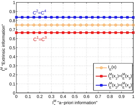
Fig. 11. Average EXIT function of Gray 16-QAM mapping and the bit-level EXIT curves for AWGN channel atEb/No=9.3 dB. The first and third bits have identical EXIT functions and similarly the second and fourth.
for 256-QAM compared with the original system. We can also observe that the achievable improvement increases with growing constellation size.
Two BICM-ID systems are also considered. In the first one, the combination of Gray mapping scheme and a rate-1/2 turbo code, which is obtained by puncturing a rate-1/3 turbo code built from two parallel concatenated 16-state RSC codes with polynomials [23,37], is applied. The size of the pseudo-random interleaver that separates both RSC codes is 30 000. The other system uses a rate-1/2 (30 000,60 000) capacity-approaching LDPC code and Gray mapping. The number of internal iterations is set to 10 iterations and the number of super iterations between mapping and coding
0 0.1 0.2 0.3 0.4 0.5 0.6 0.7 0.8 0.9 1
0 0.1 0.2 0.3 0.4 0.5 0.6 0.7 0.8 0.9 1
I E D
"Extrinsic information"
IA D "a−priori information"
R1=R3
R2=R4
Fig. 12. EXIT chart of designed LDPC codes.
4.755 6 7 8 9 10 11 12 13 14 15
10−7 10−6 10−5 10−4 10−3 10−2 10−1 100
Eb/No, dB
Bit Error Rate
MLC with MSD MLC with PDL
16−QAM 64−QAM
256−QAM
Fig. 13. BER of MLC/MSD and MLC/PDL with LDPC compo-nent codes. Different signal constellations including 16-QAM, 64-QAM and 256-64-QAM are used at spectral efficiencies of 3, 5 and 7 bit/sec/Hz, respectively.
schemes is 10. In Figs. 8 and 9, simulation results show again that the new design of BICM-ID systems using protection matching for turbo code and LDPC code, respectively, can improve the performance for different constellation sizes.
On the other hand, we apply MLC systems that use capacity-approaching LDPC codes with proper code rates in combination with different constellation sizes M=
16,64,256 to get different spectral efficiencies η=3,5,7 bit/sec/Hz. The codeword length for LDPC codes is set to 21000 bits. At the receiver, we use MSD approach for Unger-boeck mapping or PDL approach for Gray mapping.
rate R=3, we obtain the rates design R1/R2/R3/R4=
0.29/0.75/0.96/1. For MLC/PDL systems, the code rates are designed based on bit-level EXIT curves. We con-struct the average EXIT function of mapping with area un-der EXIT function C/m. Then, the areas under bit-level EXIT functions are identical to code rates. The rate design 0.67/0.83/0.67/0.83 can be obtained for 16-QAM with a to-tal rateR=3 from Fig. 11. In this approach, the exit curves for individual codes have also to match the corresponding bit-level EXIT function at the demapper as shown in Figs. 11 and 12.
Figure 13 shows the simulation results for both MLC/MSD and MLC/PDL system at different spectral ef-ficiencies. As we can see, the MLC/PLD systems provide a little improvement with eliminating error floor compared with MLC/MSD systems.
6 Conclusions
In this contribution we presented the method to improve the BICM-ID systems based on multilevel protection for differ-ent FEC coding schemes. An improvemdiffer-ent up to 1.5 dB can be obtained using new BICM-ID design based on protection matching with multiple interleavers compared to the conven-tional BICM-ID system. On the other hand, we proposed to design the MLC/PDL systems according to bit-level EXIT charts. The performance of MLC/PDL with Gray mapping provides a slightly improvement and eliminate the error floor compared to MLC/MSD with Ungerboeck mapping. More-over, the PDL approach can greatly decrease the time delay of decoding process at the receiver.
References
Hagenauer, J.: The Turbo Principle: Tutorial Introduction and State of the Arts, Symposium on Turbo Codes, Brest, France, Septem-ber 1997, 1–11, 1997.
Imai, H. and Hirakawa, S.: A New Multilevel Coding Method Using Error-Correcting Codes, IEEE T. Inform. Theory, 23, 371–377, 1977.
Li, Y. and Ryan, W.E.: Bit-Reliability Mapping in LDPC-Coded Modulation Systems, IEEE Commun. Lett., 9, 1–3, Jan 2005. Massey, J.: Coding and Modulation in Digital Communications,
Proceedings of International Zurich Seminar on Digital Commu-nication, Zurich, Switzerland, 12–15 March 1974.
Schramm, P.: Multilevel Coding with Independent Decoding on Levels for Efficient Communication on Static and Interleaved Fading Channels, IEEE International Symposium on Personal, Indoor and Mobile Radio Communications, Helsinki, Finland, 1–4 Sept 1997, 1361–1391, 1997.
ten Brink, S., Speidel, J., and Yan, R.-H.: Iterative Demapping and Decoding for Multilevel Modulation, IEEE International Confer-ence on Global Communications (GLOBECOM), Sydney, Aus-tralia, 8–12 November 1998, 579–584, 1998.
ten Brink, S.: Convergence of Iterative Decoding, IEEE Electron. Lett., 35, 1117–1119, 1999.
Ungerboeck, G. and Csajka, I.: On Improving Data-Link Perfor-mance by Increasing Channel Alphabet and Introducing Se-quence Coding, Proceedings of IEEE Int. Symp. Inform. Theory, Ronneby, Sweden, 21–24 June 1976.
Ungerboeck, G.: Channel Coding with Multilevel/Phase Signals, IEEE T. Inform. Theory, 28, 55–67, 1982.