R E S E A R C H
Open Access
Optical system design of star sensor
and stray light analysis
Mohammad Asadnezhad
1, Abdollah Eslamimajd
1*and Hassan Hajghassem
2Abstract
Background:Star sensor is one of the precise attitude determination sensors. It is an electro-optical system that takes an image from a set of stars and by comparing it with the star catalogue determines angle deviation of the satellite and modifies its attitude. Star sensor is composed of baffle, optical system, detector, and electronic and image processing system. Methods:In this article, first subsystems of a star sensor is briefly described, then by determining the optical parameters, an optical system with proper quality is designed, and the tolerances are considered.
Results:The simulation results and the optical evaluation curves indicate that the image quality is close to the diffraction limit. Next, stray lights from off-axis sources like the sun, are analyzed. For this purpose, the main parameters of baffle designing such as its dimensions and arrangement of the vanes inside it, are determined and then a cylindrical baffle with internal vanes for the star sensor is designed.
Conclusion:Results show that stray lights reduced 10−11times with the presence of baffle and its vanes.
Keywords:Star sensor, Attitude determination, Navigation, Optical system, Stray light, Baffle
Background
Navigation is one of the most important subjects in space missions divided into position determination and attitude determination. Determining the location and angular co-ordinates of spacecraft according to a fixed coordinate sys-tem is called position determination and attitude determination, respectively [1,2]. In most cases, the iner-tial navigation system is used for spacecraft navigation. In-ertial navigation system may have some errors in the long term due to natural factors such as gravity and magnetic effects or for reasons such as gyro axis deviation and ac-celerometers error. These effects are numerically low, but they would be effective with a high repetition in the long term. Therefore, this cumulative error sometimes must be corrected by an auxiliary navigation system [3].
As Fig.1shows, there are many ways to position and atti-tude determination of spacecraft [2]. Star sensor is an important and high precision attitude control system [4–9]. It is an electro-optical system taking a picture from a set of stars (as point sources at infinity [6, 7]) in celestial sphere and comparing it with the same star pattern from reference
star catalogue to calculate the angular deviation of the satel-lite to a specific reference [9–11]. Finally, this information is sent to inertial guidance and control system to attitude correction of satellite [12,13].
In this article, an optical system for a star sensor is designed and then with stray light analysis, a suitable baffle is designed for it. Thus, this article is divided into three parts. In the first part, star sensor and its subsystems are discussed. In the second part, optical design, optimization, image qual-ity and tolerancing are explained in detail. In the third part, by analyzing stray light, a suitable baffle is designed for it.
Star sensor
As it is mentioned above, star sensor is a photographic optical system combined with image processing program to calculate the angular deviation of satellite from station-ary reference object. Star sensors are divided into two gen-erations, and their characteristics are shown in Table1.
As can be found from Table1, second generation star sensors have better advantages. Although the star identi-fication algorithms with sub-pixel accuracy and lost-in-space algorithms are complicated, nowadays, the second generation star sensors are used for autonomous naviga-tion in space missions [9].
* Correspondence:[email protected]
1Department of Electrical and Electronic Engineering, Maleke-ashtar University of Technology, Tehran, Iran
Full list of author information is available at the end of the article
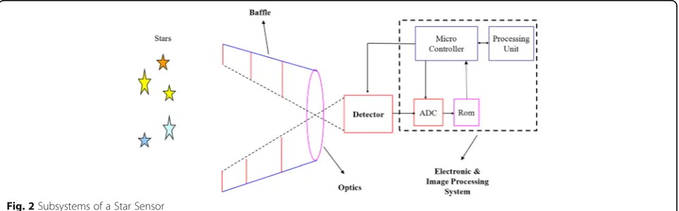
Star sensor consists of four sections that are discussed as follows (Fig.2) [5,13,14].
1. Baffle
2. Optical System 3. Detector
4. Electronic and image processing system
Baffle
Since there are not any particles in space and the dis-tance between molecules is very long, the intensity of bright sources such as the sun, is unscattered and high. Thus, due to high intensity sources in the field of view (FOV) of star sensor, the detector is saturated in a short time, and recognition of star from the bright background
is virtually impossible [5]. Therefore, to identify low magnitude stars (until mv= 7) by the detector, the inten-sity of out of field stray light sources, especially the sun, must be attenuated. Baffle is an opto-mechanical device that prevents coming stray light out of field into the optical system of star sensor [15–17].
Detector
New generation of star sensors are improved in terms of light weight, small size, low power consumption and intelligent systems [7, 8]. For this purpose, using active pixel sensor (APS) instead of charge coupled device (CCD) detectors is more useful. APS compared to CCD has more advantages such as higher dynamic range, lower power consumption, smaller size and higher
Fig. 1The ways of attitude and position determination
Fig. 2Subsystems of a Star Sensor
radiation tolerance [9,18]. Therefore, they become more interesting to be utilized in space explorations and many attitude sensors applications and space imaging navigation [17–20]. Accordingly, APS detector that its spectral response is shown in Fig.3, is used in this article. It is obvi-ous from this figure that this detector has higher responses to the wavelength from 0.55 to 0.85μm. The detector spec-tral response is desirable for different specspec-tral classes of stars, and its maximum is approximately 0.6 μm. Table2 shows the characteristics of the APS detector [21].
Optical system and image processing
As mentioned in section Star sensor, a star sensor con-sists of an optical system with a detector and an image processing program running in an on-board computer of microsatellite. The optical system takes images from stars as point sources in any region of celestial sphere in its FOV (Fig. 4) [8, 9]. Since stars are fixed in cosmos relative to inertial space [7], then they are the best candi-dates for attitude determination.
The taken image from the optical system is compared with a precise star catalogue saved in on-board
computer of satellite. Then, the centroid position of each star in the FOV is calculated by centroid algorithm. Eq. (1) and (2) show the position of star in X and Y direc-tion, respectively [11,22].
Xc¼
P
xiФðxi;yiÞ
P
Фðxi;yiÞ
ð1Þ
Yc¼
P
yiФðxi;yiÞ
P
Фðxi;yiÞ
ð2Þ
Where (xi, yi) is the position of ithpixel andФ is the
in-tensity of imaged star on ithpixel. It is obvious from these equations that the star sensor optical system must be designed near diffraction limit. The position of star image on a pixel must be calculated less than one pixel surface accuracy to achieve arc second order accuracy. Thus, im-aging a star on one pixel, as agreed criterion in normal op-tics, is not satisfactory. To achieve sub-pixel accuracy, the image of a star must be distributed on a set of pixels by de-focussing in the first step [6,9,13]. Next, a program must be written to calculate the position of star on the detector pixels. For this purpose, the interpolation algorithms are generally used [9,11,22].
Fig. 3Spectral response of selective APS detector [21]
Table 2Characteristics of selective APS detector
Parameter Value
Resolution 1024 × 1024
Pixel Pitch 15x15μm
Spectral Range 0.4-1μm
Quantum Efficiency 20%
Dynamic Range 72db
Table 1Characteristics of two generations of star sensors [10, 13]
1st generation 2nd generation Field of View Wide not very wide
Power > 20 W < 5 W
For precise attitude determination, the location of star in celestial sphere (Fig. 4) should be imaged on the detector without any position and angular deviation. For this purpose, aberrations affecting position of object like distortion and lateral color must be reduced or eliminated.
Methods Optical design
Primary parameter of focal length, FOV, F# and spectral range are essential to design optical systems [23, 24]. The following relation can be made between detector dimensions, FOV, and focal length in the imaging system:
tanFOVx
2 ¼
X
2f ; tan FOVy
2 ¼
Y
2f ð3Þ
WhereFOVxandFOVyare the field of view of the
sys-tem in horizontal and vertical direction according to the detector, respectively;X and Yare the width and length
of the detector, respectively, and f is the focal length of the optical system.
As it is obvious in Eq. (3), there must be a tradeoff between focal length and FOV. Increasing each one will decrease the other.
The F# is one of the most important parameters of any optical system controlling the energy entering the detector through entrance aperture of the optical system. Since F# controls magnitude range of stars in the FOV, it plays an important role in star sensor. With a constant value of focal length, high amount of F# decreases aper-ture size, limiting the stellar magnitude. The low amount for F# increases the entrance aperture size, leading to catch low-bright stars but increases the weight and length of the optical system. In this situation, high order aberrations appear, resulting in a more complicated optical system [23,24].
During the optical design process, our trend is to make an optical system with FOV as wide as possible because more stars in the FOV lead to easier achieve-ment of star pattern and better attitude determination. However, as mentioned before, it decreases the focal length, which causes other problems. In such situations, the star catalogue and star identification algorithm be-come more important. The spectral range is determined by detector spectral range and spectral class of stars.
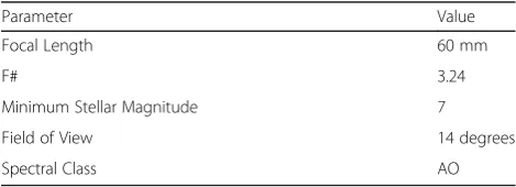
According to the conceptual design, the parameters in Table3are calculated for optical system.
As mentioned in section Optical system and image processing, the optical system must satisfy the following cases:
Fig. 4Star sensor (principal planes H &H`) makes the image of a star location somewhere in celestial sphere
Table 3Principal parameters needed to design the optical system
Parameter Value
Focal Length 60 mm
F# 3.24
Minimum Stellar Magnitude 7
Field of View 14 degrees
Spectral Class AO
a) According to spectral response of detector and star spectral class, chromatic aberration must be corrected.
b) Image magnification must be identical in full FOV. c) Optical system must be light weight and compact
[8]. The numbers of optical components must be minimized to facilitate processing and assembly.
Stray light analysis and baffle design
During navigation by star sensor, the image quality may be unexpectedly reduced by stray light sources. Stray light is the unwanted light reaching the detector and re-ducing the image quality. These incoherent and discrete lights do not follow the normal optical path of the im-aging system [25–30]. Stray light in an optical system may lead to restrictions on detector dynamic range, arti-ficial effects (ghost) in the image, and blurring as well as reducing image contrast, signal to noise ratio, resolution, and desirable FOV [25–28].
Using baffle is one of the ways to control and reduce stray light. As mentioned in section Baffle, baffle is a highly important part of star sensor. It is an opto-mechanical device installed at the entrance aperture of the star sensor to protect the optical system against the external stray light sources such as sun, earth, moon and other celestial bodies [16,17,27,31]. The satellite is also a source of stray light by reflecting the light from the in-tense sources. All these sources are able to saturate the detector and reduce the probability of finding low stellar magnitudes. To avoid this problem, in this work, a suit-able baffle is designed for the designed optical system.
Result and discussion Optimization of optical design
Considering the conditions in section Optical Design, three candidates for start point are found: the frontal aperture optical system, the telecentric [8] type of optical systems and very simple symmetric Double Gauss sys-tem. All these types can control the distortion easily. Optical design of Double Gauss system is easier relative to other types. In addition, its opto-mechanics is easier. Its tolerances are looser, and fabrication limits are less than them, especially relative to telecentric system.
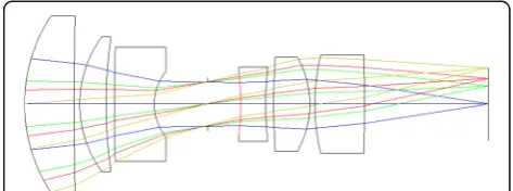
Therefore, Gaussian optical system as a start point was chosen in this work (Fig.5).
As can be seen from Fig. 5 the second lens and the third lens, as well as the fourth lens and the fifth lens are laminated in the initial structure. It is necessary to separate the second lens from the third lens and the fourth lens from the fifth lens to prevent degumming in space environment. Thus, the structure of the optical system needs to be optimized. Furthermore, the small volume and mass of star sensor can be reached by min-imizing the radial and axial dimensions of the lenses. By considering optical parameters in Table3, Double Gauss system is designed and optimized by ZEMAX optical design software.
With considering the characteristics of the optical sys-tem and the requirements to determine centroid position in image processing, monochromatic aberrations should be controlled. It is obvious from the spherical aberration coefficient formulas that the higher the refractive index of lens material at the same focal power, the smaller the spherical aberration of the lens. Moreover, high refractive index optical glass has less requirement of the lens’ thick-ness. So, the structure of the optical system will be com-pact, and the miniaturization of the optical system is obtained. On the other hand, astigmatism and field curva-ture should be controlled to ensure that the star spot size is the same over the FOV. Since the aim of this work is to have a wide FOV, the distortion aberration is high and reducing it is too important. Distortion is the displace-ment of the image from the paraxial position and is differ-ent from other aberrations. So it causes displacemdiffer-ent of the star image, especially at the end of the FOV, and changes the center of the star. Therefore the distortion in the star sensor should be controlled.
Double Gauss system is a symmetric, light weight and compact optical system. This system is able to reduce or eliminate symmetric aberrations such as spherical, astig-matism and distortion. Optimization process was per-formed for peak wavelengths of the selective APS detector (Fig.3), being harmonized with the star spectral class. After optimization process, a quasi-symmetric optical system (Fig.6) was designed.
The designed optical system is composed of six lenses. The first, second, fifth and sixth lenses are positive lenses,
and the third and fourth lenses are negative lenses. This structure has a small volume and can reduce stray light.
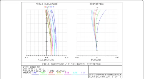
Optical evaluation curves show that the distortion (Fig. 7) and lateral color (Fig. 8) are enough low. Dis-tortion is less than 0.03% at full FOV. The optimization program by destroying the symmetry of
optical system decreased the field curvature and chro-matic axial color aberrations. Accordingly, as Fig. 7 obviously shows, the field curvature is less than 0.05 mm that is satisfying.
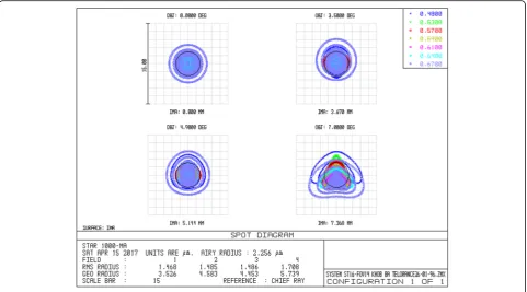
Spot diagram (Fig.9) shows that maximum root mean square (RMS) of spot radius for full FOV is less than
Fig. 7Field curvature and Distortion of optimized system
Fig. 8Laterl color curve
2 μm. As this figure shows, beams are gathering in a geometric diameter of 11–12μm at full FOV.
The geometric radius is distributed on almost 45% of the whole surface of each pixel. It is an advantage in fabrication process since fabrication errors increase the radius spot. Therefore, looser tolerances are needed, which reduce the cost and complexity of optical system.
This optical system has six lenses (twelve surfaces that all of them are spherical), and its overall length is 93.49 mm. It includes fewer types of lenses and has wide FOV, than the congeneric optical systems, and its structure is simple. Therefore, the optical sys-tem is minimized in volume and mass, and its manu-facturing process is easier. Besides, fully separated optical structure is designed to prevent gluing surface from degumming in space orbit, and it meets the requirements of design and practical engineering for small star sensor.
Tolerancing of optical system
Tolerance analysis is one of the most important steps in optical design. By tolerance analysis, the maximum and minimum fabrication error limits and the manu-facturability of optical system are determined. Table 4 shows the tolerances for the designed optical system. These are normal optical tolerances, which are achievable for most manufacturers.
Tolerance analysis is performed by the ZEMAX software with two methods including sensitivity ana-lysis and Monte Carlo anaana-lysis. In these analyzes the adjustment parameter (compensator) and the per-formance criteria are the back focus and RMS spot radius respectively. Table 5 shows results of toleran-cing by sensitivity analysis method. As can be seen, nominal RMS spot radius is equal to 1.5 μm. While estimated RMS spot radius is about 8.3 μm.
Tolerancing by Monte Carlo analysis method shows that 90% of tolerances have RMS spot radius of approxi-mately 8.1μm (Table6). Furthermore, 80% of tolerances lead to RMS spot radius of 7.7 μm that is satisfying by
Fig. 9Spot diagram
Table 4Tolerances of designed optical system
Parameter Tolerance
Radius of Curvature R/1000 mm
Thickness 0.1 mm
Decenter X 0.05 mm
Decenter Y 0.05 mm
Tilt X 0.0167 degree = 1 arc minute Tilt Y 0.0167 degree = 1 arc minute
Table 5Estimated performance changes based upon Root-Sum-Square method
considering the selective detector with 15μm pixel pitch and easy manufacture process.
Results shown in Table 7indicate that the mean devi-ation of nominal criterion is 6μm. The nominal criter-ion is a spot with an RMS radius of 1.5μm.
The analysis of these two methods of tolerancing shows that the system has a good tolerance.
Principle of baffle design
The parameters and characteristics that must be consid-ered in baffle design are [16,17,29,32]:
a- Dimensions: Dimensions of baffle are strongly af-fected by entrance pupil diameter of optical system, FOV and exclusion angle of the sun.
b- Vanes arrangement: Location, size and shape of vanes should be designed to meet the following conditions:
b-1- The vanes should be designed so that none of the optical elements could directly see the places illuminated by intense stray light sources.
b-2- The stray light has the maximum reflections in-side the baffle and between the vanes before reaching the optical elements.
c- The surface of the baffle must be coated by a black absorbing material.
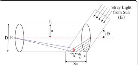
Figure10shows an example of no vane baffle that its angle relative to the sun axis isθ.
According to Fig. 10, if the aperture diameter of the baffle isD, then:
tanϴ¼ D
Sm ð
4Þ
As Fig. 10shows, to prevent the entrance of sunlight to the optical system directly, the optical baffle length
must be always larger than Sm. In other words, we
should have:
L>Sm→ L> D
tanϴ ð5Þ
As Fig. 10 shows, for a no-vane optical baffle with a diameter equal to that of the optical system, the amount of stray light entered to the optical system is obtained from the following formula [17]:
Ec¼ρEi
sinθ
π
Z Sm
0
L−S
ð Þ4S2−S2tan2θ
L−S
ð Þ2þ
a2
2 ds ð6Þ
Where Eiis the solar irradiance normal to the line of
sight,θis the angle of the sun with respect to the optical axis,S is the distance of baffle that is illuminated,ρ is a diffuse reflectivity of the inner wall of the baffle,Lis the baffle length, and ais its radius. According to the above explanation and Fig. 10, if the baffle is longer, the stray lights become further weakened.
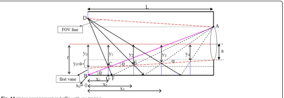
Vanes designing
The vanes are structures in the baffle preventing scatter-ing from walls. In an optimal state, baffle and vanes must be designed so that with a minimum size and number of vanes, maximum possible efficiency can be obtained. In this step, ray tracing is used to determine the position and height of the vanes. The height of the first vane should be determined according to entrance aperture diameter, FOV of the optical system and baffle length. Line AB in Fig.11 is the part of baffle wall, which could be seen by the upper edge of the lens. The position and height of the second vane is determined by the cross of AB and FOV line of the system. The position and height of other vanes are cal-culated by this method.
According to Fig. 11, the position and height of vanes can be determined using Eqs. (7–9):
xnþ1¼ y0−ynþ1
L
y0−a
ð7Þ
Table 6Deviation of nominal criteria by tolerances in Table4
Probability
Criteria (RMS spot radius in mm)
90% < 0.00818804
80% < 0.00776495
50% < 0.00589145
20% < 0.00405820
10% < 0.00386784
Table 7statistics for deviation from nominal criterion (RMS Spot Radius in mm)
Nominal 0.00153182
Best 0.00339054
Worst 0.01044278
Mean 0.00601417
Std Dev 0.00185363
Fig. 10No vane cylindrical optical baffle with angleϴrelative to sun
ynþ1 ¼r−
rþa
1þzn ð
8Þ
zn¼2a r−y0þxny0−a
L
y0þr
y0þyn
−1
ð9Þ
Where xnand (r-yn) are position and height of the n
th
vane, respectively;ais the semi diameter of the lens;ris the semi diameter of the baffle, andLis the baffle length.
Designed baffle for the optical system
The baffle designed for the optical system is a tube with two baffles combined with each other (Fig. 12). The front baffle is a shield against direct sunlight. The rear one rejects or attenuates the remaining stray light reflected into optical system from the front baffle walls.
In Fig. 12, αis the half FOV,βis the maximum angle between the sun and optical axis which is 30°, D1 is
entrance aperture diameter, which is 35.676 mm. For the baffle design, a safety margin of 1.5° for vanes was added to the half of FOV to reduce the edge scattering. According to the geometrical relation in Fig. 12, for
front baffle length (X2), rear baffle length (X1) and final
length of the baffle (L), we have:
X1¼ D1
tanβ−tanα ð10Þ
X2¼ tanβþ tanα
tanβ−tanα
ð Þ2D1 ð11Þ
L¼X1þX2¼
2 tanβ tanβ−tanα
ð Þ2D1 ð12Þ
The above equation shows that the baffle length (L) depends on FOV, exclusion angle of the sun and en-trance aperture diameter.
According to Eqs. (7–9), position and height of vanes in the baffle were calculated (Table8). Results show that six vanes in the baffle are enough to prevent the bright sources stray light in space.
The metal chosen for baffle should be low in weight, strong, inexpensive and provide the strength necessary for the survival of launch. 6061 and 7075 aluminum al-loys are the most applicable and most widely used
Fig. 11Vanes arrangement in baffle with ray tracing
metals in aerospace industries and are best choices for baffle manufacturing purposes which their strength are comparable to steel [32–34]. Therefore, the 6061 aluminum alloy is used in this work. Because it is cheaper and more available than 7075 alloy.
To evaluate stray light performance in the optical sys-tem, particularly in the visible spectrum, the best method is to measure the point source transmittance (PST) at the detector location. PST is equal to the ratio of stray light irradiance in the desired location to light irradiance at dif-ferent angles relative to the optical axis at the entrance aperture of the optical system [16,27, 32]. In the follow-ing, to evaluate the effect of baffle and vanes on control-ling and reducing stray light, after modecontrol-ling the baffle in TracePro software, PST values are calculated. In this step to complete the simulations, the inner surface of the baffle and vanes are coated by a typical black coating with a 90% absorption coefficient which is available to all manufac-turers. Figure13shows the corresponding PST curves.
The above curve shows PST in a condition that baffle has no vanes and the below curve shows PST in a condition that baffle has optomecanical vanes. As these curves shows, using baffle and vanes caused the stray light to dramatically decrease. Figure 13 indicates that PST values of the two modes decrease with the increase of source angle.
Furthermore, the vanes caused the PST to be approxi-mately 10 to 15 times less than the condition of baffle with-out vanes. On the other hand, existence of baffle with vanes leads to reduce the value of PST to 10−11in off-axis angles. It has better performance of stray light suppression.
Conclusion
In this study, an optical system based on Double Gauss was designed for the star sensor. The purpose of the de-sign was to calculate a simple and lightweight optical system meeting all of the parameters of the optical sys-tem. For this purpose, the APS detector, that is suitable for space applications, was used. The optical system is made up of six spherical lenses, all of which are available in Schott, and its structure is simple. The focal length of the optical system is 60 mm, its field of view is 14°, and its overall length is 93.49 mm. The results of simulation with ZEMAX software show that the designed optical system has high image quality. RMS size of the spot is less than 4μm, and its distortion in the full FOV is less than 0.03%. Moreover, the results of tolerancing show that the system retains its optical quality by considering normal tolerances.
In the following, with stray light analysis, a simple, light weight and short optical baffle with 6 inner vanes to control and reduce stray lights due to bright sources in space, especially the sun, is designed in TracePro soft-ware. Finally, to evaluate the baffles and vanes, PST in different modes were calculated and simulated at the detector location. The results of the simulation show that using vanes in the baffle has improved the perform-ance of the system against stray lights. Furthermore, the PST curve shows that its value has been reduced to 11− 10
times at off-axis angles, indicating a proper baffle per-formance against stray lights.
Abbreviations
APS:Active pixel sensor; CCD: Charge coupled device; FOV: Field of view; PST: Point source transmission; RMS: Root mean square
Funding ‘Not applicable’.
Availability of data and materials ‘Not applicable’.
Authors’contributions
MA carried out the initial studies, designed of optical system and baffle and drafted the manuscript. AE participated in the design of the study and performed the statistical analysis. HH conceived of the study, and participated in its design and coordination and helped to draft the manuscript. All authors read and approved the final manuscript.
Competing interests
‘The authors declare that they have no competing interests’.
Publisher’s Note
Springer Nature remains neutral with regard to jurisdictional claims in published maps and institutional affiliations.
Fig. 13Log PST as a function of source angle
Table 8Position and height of vanes in the baffle
Vane number Position (mm) Vane number Position (mm)
0 X0 0.000 3 X3 102.887
Y0 51.463 Y3 36.086
1 X1 20.294 4 X4 163.133
Y1 48.430 Y4 27.082
2 X2 53.682 5 X5 222.723
Y2 43.440 Y5 18.176
Author details
1Department of Electrical and Electronic Engineering, Maleke-ashtar University of Technology, Tehran, Iran.2Department of New Sciences & Technologies, University of Tehran, Tehran, Iran.
Received: 12 December 2017 Accepted: 4 March 2018
References
1. Titterton, D., Weston, JL: Strapdown inertial navigation technology, vol. 17. IET (2004)
2. Wertz, JR (ed.): Spacecraft attitude determination and control, vol. 73. Springer Science & Business Media (2012)
3. Liebe, C.C.: Star trackers for attitude determination. IEEE Aerosp. Electron. Syst. Mag.10(6), 10–16 (1995)
4. Kawano, H., Shimoji, H., Yoshikawa, S., Miyatake, K., Hama, K., Nakamura, S.: Optical testing of star sensor (I): defocus spot measuring technique for ground-based test. Opt. Rev.15(2), 110–117 (2008)
5. Wang, G., Xing, F., Wei, M., Sun, T., You, Z.: Optimization method for star tracker orientation in the sun-pointing mode. Chin. Opt. Lett.15(8), 081201 (2017)
6. Zhao, S., Wang, Y., Wang, H.: Study on detection sensitivity of missile-borne star tracker. (2012)
7. Hua-Ming, Q., Hao, L., Hai-Yong, W.: Design and verification of star-map simulation software based on CCD star tracker. In: Intelligent Computation Technology and Automation (ICICTA), 2015 8th International Conference on, pp. 383–387. IEEE (2015)
8. Wang, S., Geng, Y.: Large field and high precision optical system for star tracker. In: Information and Automation (ICIA), 2014 IEEE International Conference on, pp. 484–489. IEEE (2014)
9. Zhang, P., Zhao, Q., Liu, J., Liu, N.: A brightness-referenced star identification algorithm for aps star trackers. Sensors.14(10), 18498–18514 (2014) 10. Birnbaum, M.M.: Spacecraft attitude control using star field trackers. Acta
Astronautica.39(9–12), 763–773 (1996)
11. Huffman, K, Sedwick, R, Stafford, J, Peverill, J, Seng, W: Designing star trackers to meet micro-satellite requirements. InSpaceOps 2006 Conference, p. 5654, (2006)
12. Liebe, C.C., Gromov, K., Meller, D.M.: Toward a stellar gyroscope for spacecraft attitude determination. J. Guid. Control. Dyn.27(1), 91–99 (2004) 13. Eisenman, A.R., Liebe, C.C., Jorgensen, J.L.: The new generation of
autonomous star trackers. (1997)
14. Mazy, E., Defise, J.-M., Plesseria, J., De Vos, L.: Optical Design of the INTEGRAL Optical Monitoring Camera. In: Proc. SPIE (1998)
15. Mazy, E., Defise, J.-M., Plesseria, J.: INTEGRAL Optical Monitoring Camera Stray-Light Design. In: SPIE Conference (1998)
16. Scaduto, L.C., Carvalho, E.G., Santos, L.F., Yasuoka, F.M., Stefani, M.A., Castro, J. C.: Baffle Design and Analysis of Stray-Light in Multispectral Camera of a Brazilian Satellite. Annals of Optics, XXIX ENFMC (2006)
17. Lee, Y.S., Kim, Y.H., Yi, Y., Kim, J.: A baffle design for an airglow photometer onboard the Korea sounding rocket-iii. J Korean Astronomical Soc.33, 165– 172 (2000)
18. Yadid-Pecht, O., Clark, C., Pain, B., Staller, C., Fossum, E.R.: Wide dynamic range APS star tracker. In: Proc. SPIE, pp. 82–92 (1996)
19. Boldrini, F., Monnini, E., Procopio, D.: Applications of APS detector to GNC sensors. Eur Space Agency-Publications-Esa Sp.516, 33–40 (2003) 20. Hopkinson, G., Purll, D., Abbey, A., Short, A., Watson, D., Wells, A.: Active pixel
array devices in space missions. Nuclear Instruments and Methods in Physics Research Section A: Accelerators, Spectrometers, Detectors and Associated Equipment.513(1), 327–331 (2003)
21. Uwaerts, D.: STAR 1000 Detailed Specification. In: fillfactory (2006) 22. Samaan, M.A.: Toward Faster and More Accurate Star Tracker Sensor Using
Recursive Centroding and Star Identification. Texas A&M University. A Dissertation Proposal (2002)
23. Warren JS. Modern optical engineering. The Design of Optical Systems. 2007:205–216.
24. Fischer, R.E., Tadic-Galeb, B., Yoder, P.R., Galeb, R.: Optical System Design. McGraw Hill, New York (2000)
25. Park, J.-O., Jang, W.-K., Kim, S.-H., Jang, H.-S., Lee, S.-H.: Stray light analysis of high resolution camera for a low-earth-orbit satellite. J Opt Soc Korea.15(1), 52–55 (2011)
26. JI, R.S.J.Z.Y., Weimin, S.: Stray Light Analysis and Baffle Design of Remote Sensing Camera for Microsatellite. In: Proc. of SPIE Vol, pp. 75060T–775061, In (2009) 27. Fest, E.C.: Engineers, S.o.P.-o.I.: Stray light analysis and control. SPIE Press,
Bellingham (2013)
28. Park, J.-O., Jang, W.-K., Kim, S.-H., Jang, H.-S., Lee, S.-H.: Optical noise removal in the focal plane of the Spaceborne camera. J Opt Soc Korea.
15(3), 278–282 (2011)
29. Du, B., Li, L., Huang, Y.: Stray light analysis of an on-axis three-reflection space optical system. Chin. Opt. Lett.8(6), 569–572 (2010)
30. Kumar, M.S., Narayanamurthy, C., Kumar, A.K.: Design and analysis of optimum baffle for a Cassegrain telescope. J. Opt.45(2), 180–185 (2016) 31. Hu, X., Wang, W., Hu, Q., Lei, X., Wei, Q., Liu, Y., Wang, J.: Design of
CASSEGRAIN telescope baffles with honeycomb entrance. Chin. Opt. Lett.
12(7), 072901 (2014)
32. Nejad, S.M., Madineh, A.B., Nasiri, M.: Baffle design and evaluation of the effect of different parameters on its performance. Optik-Int J Light Electron Opt.124(23), 6480–6484 (2013)
33. Cascioli, V., Borsini, S., Gargiulo, C., Trampus, P., Bucconi, A., Scarabottini, P., Scolieri, G., Molina, M., Vettore, C.: The AMS star tracker thermal qualification overview. In: SAE Technical Paper (2007)
![Table 1 Characteristics of two generations of star sensors [10,13]](https://thumb-us.123doks.com/thumbv2/123dok_us/9620076.1944213/3.595.304.542.100.184/table-characteristics-generations-star-sensors.webp)