A MODEL-DRIVEN VIEW TO META-PROGRAM
DEVELOPMENT PROCESS
Vytautas Štuikys, Robertas Damaševi
č
ius, Aleksandras Targamadz
ė
Software Engineering Department, Kaunas University of Technology
Studentų 50-415, LT-51368, Kaunas, Lithuania
e-mail: [email protected]; [email protected]; [email protected]
Abstract. We propose a general framework for the model-driven analysis of the meta-program development pro-cesses. Our approach considers: 1) a hierarchy of related meta-models and models that are represented at different levels of abstractions for problem and solution domains; and 2) vertical transformations of the introduced meta-models and models for lowering the abstraction level of their representation until the executable specification. The framework provides a theoretical background to understand the meta-program development process and creates well-grounded pre-conditions for the semi-automatic design of meta-programs. We also formulate the requirements for tools to support such automation.
Keywords:meta-programming, model-driven development, meta-program, meta-model.
1. Introduction
The development of modern complex software systems is impossible without representation of do-main concepts at multiple levels of abstraction, wide-range reuse and automatic program generation. Cur-rently, two software development methodologies have been widely researched and used for this purpose: Model-Driven Engineering (MDE) [1] and Product Line Engineering (PLE) [2].
The PLE methodology focuses on maximizing re-use in software product lines (i.e., families of prog-rams that share common assets), and mainly operates with features (i.e., externally-visible characteristics of programs that can be recombined in different ways to achieve different versions of program functionality). First, architecture of the product family is created based on product communalities and planned vari-abilities. Then different product variants are derived from this architecture by reusing components and structures as much as possible and using a variety of component-based and generative reuse techniques [3].
The MDE methodology, on the other hand, advo-cates for the use of domain models (i.e., abstractions of domain concepts), which are independent of cha-racteristics of technological platforms, as the key artifacts in all phases of the software development process. Such models can be introduced at multiple levels of abstraction, i.e., also above other models, thus leading to the multi-level modeling hierarchies. Models are created using concepts defined in a meta-model that represents domain concepts, relationships
and semantics. Domain models are then transformed into platform-specific models using transformation rules, which are defined by meta-model concepts: a rule (rules) transforms source model elements, which conform to a source meta-model, into target model elements, which conform to a target meta-model [4].
In this paper, we apply the concepts of both metho-dologies to the development of meta-programs. We treat meta-programming [5, 6] as a process of deve-loping meta-programs in a very abstract way. Meta-programs are program generators that produce other programs. Being executable higher-level specifica-tions, meta-programs are much more complicated items than the product they produce. Abstractly, meta-programming (or building of program generators) links two domains: problem domain (a domain model that represents domain concepts and their relation-ships) and solution domain (meta-programming tech-niques used to develop meta-programs).
hardware design [9], and business processes design [10]) and apply it to the development of meta-prog-rams. Our approach considers: 1) a hierarchy of rela-ted meta-models and models that are represenrela-ted at different levels of abstraction for both domains; and 2) various kinds of transformations of the introduced meta-models and models aiming to lowering the abst-raction level of their representation until the execut-able specification is achieved.
To our knowledge, the proposed model-driven framework, when the problem domain is presented by Feature Diagram (FD) at three levels (i.e., meta-model, model and model instance), in the context of heterogeneous meta-program development, is discus-sed for the first time; though many other authors considerably contributed to the development and ex-tension of the FD notation and heterogeneous meta-programming itself in recent years (see related works). We hope that our framework creates well-grounded pre-conditions for semi-automatic design of meta-programs.
The rest of the paper is structured as follows. Sec-tion 2 overviews the related works. SecSec-tion 3 de-scribes a framework for the model-driven analysis of the meta-program development processes. Section 4 provides an interpretation of transformations within the framework. Section 5 formulates the requirements for tools to support (semi-) automatic development of meta-programs. Finally, Section 6 presents summary and conclusions.
2. Related works
The overview we present below consists of two parts. First, we analyze the Model-Driven Develop-ment (MDD) and transformations (OMG view [4]); and then we focus on the feature–based models and their transformations.
MDD is based on the principle of separating the description of abstract properties and logic of an application from a description of its platform-specific implementation, and the automation of the transforma-tion of the former into the latter using Model Trans-formation Tools (MTTs). The most mature formulation of this vision at present is the OMG's Model-Driven Architecture (MDA) [11], which refers to a high-level description of an application as a platform indepen-dent model (PIM) and a more concrete implementa-tion-oriented description as a platform specific model (PSM).
An important aspect of the MDD approach is model transformation: a transformation of one or more source models to one or more target models, based on the meta-models of each of these models. Such transformations are defined by transformation/map-ping rules and can be summarized as taxonomy [12] that can help developers in deciding which model transformation approach is best suited to deal with a particular problem. The models themselves can be
represented differently (using formal, textual, graphi-cal notations), but the most suitable formalism is based on graph transformation rules. Grunske et al. [13] provide an overview about the needed concepts to apply graph transformations in the context of model-driven engineering and show the technical feasibility based on several tools and applications.
In feature modeling, especially for PLE, formal models of product features and different interactions between them are important for further implementa-tion of meta-programs or software generators imple-menting product lines. Janota and Kiniry [14] present a formalized feature modeling meta-model to support reasoning about feature models, feature trees and their configurations. Westfechtel and Conradi [15] present a formal description of multi-variant models, describe transformation processes on such models including change and product configuration, and discuss the construction and representation of models incorpo-rating multiple variants. Ebraert et al. [16] describe a formal model of change-oriented programming based on Feature Diagrams (FDs), in which features are seen as sets of changes (or high-level transformations) that can be applied to a source program.
We can summarize that feature modeling is very well adapted towards the description of domain vari-ability but it lacks structural organization and expres-siveness that is needed for developing complex soft-ware systems and that shortcoming may be provided by using the MDE approach. On the other hand, MDD notations such as UML lack capabilities for modeling variability and software families (product lines). Ef-forts to overcome this gap include extension of the UML meta-model to include features for variability modeling [17] or using both UML and feature models for modeling a domain [18].
3. Framework for model-driven analysis of the meta-program development processes
3.1. Basic assumptions and terminology
First, we need to introduce some assumptions to-gether with relevant terminology that enable to receive some validity of the assumptions and better under-standability of the topic. The assumptions are as follows.
1. The framework focuses on the meta-program design phase only using the model-based approach.
2. We use feature-based models to describe and represent a domain model and problem domain tasks. The reason is that feature models are suitable to ex-press, analyze and configure variability and commona-lity [19] of domain tasks to be implemented using meta-programming.
high-level model to specify and create meta-programs. Note that FDs still is an open notation with many proposals and extensions introduced in recent years (for more details see, e.g., [20]). Here we adopt the FD notation, which we call the canonical form. It has been devised as an extension of the generic feature diagram [20] with explicitly represented context [21].
4. As it is not reasonable to build meta-program-ming-based generators for any domain that is de-scribed by a FD, some restrictions should be introduced to that model. Restrictions relate to the notation itself, domain scope, i.e., complexity of feature diagrams [21] and extent of variability that is expressed through variant points and variants.
5. The model-based approach to deal with meta-programming directly relates to program and model transformations. Thus we need to introduce relevant terminology. We use meta-modeling concepts and techniques inherited from the OMG approach [4] to describe the framework for both problem and solution domain abstractions (see also Figure 2) as follows: meta-model, program transformation, model transfor-mation, model mapping, vertical transfortransfor-mation, hori-zontal transformation, model merging.
6. We accept the vision proposed in [12] that the term “model transformation” encompasses the term
“program transformation” since a model can range
from the abstract analysis models, over more concrete design models, to very concrete models of the source code. Transformation is a general term that can be
used either “at design time” or “at run time” when the transformation context is not essential and is omitted (it is assumed that transformation is the automatic process); as in reality “at design time” transformations are not yet always automatic, we use the term
“mapping”. By merging we mean a mechanism of
how source models are combined together to produce the output model. Horizontal transformation (or
map-ping) defines transformations at the “same”
abst-raction level (no matter high or low), while vertical
transformation (or mapping) defines transformations
at the “different” abstraction levels (usually adjacent from higher to lower in terms of forward engineering, but not in reverse engineering). Instantiation is the process of the vertical transformation when a model
instance is created from its meta-model.
3.2. Description of the framework
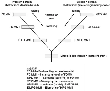
The framework is represented using the Y-chart (see Figure 1). The Y-chart [22] is a tripartite repre-sentation of design process from different points of view. Here we consider problem domain, solution domain, and the result of design, i.e., executable sys-tem specification. Every branch has crossings which denote the specific level of abstraction. Traversing along the branches, a designer can refine or abstract designs (vertical transformations), while a move to another branch means a change of the representation, i.e., a horizontal transformation.
In Figure 1, we outline the Y-chart in which the abstraction levels and a hierarchy of models for each domain are specified. Such a structure will serve as a tool to present the mapping framework later. Schema-tically, the left branch of the structure represents the abstraction levels and models of the problem domain. The right branch represents the solution domain, the abstraction levels and models of the solution domain. The vertical branch of the Y-chart represents the product (i.e., meta-specification or meta-program) to be created when the framework is implemented. At the highest level there are meta-models for each (left and right) branch of the structure. At the next (i.e., intermediate) level there are model instances and below them – elements of model instances. In the next section, we describe this abstraction and model hierarchy in detail.
As we can see from Figure 1, the design phase is extremely rich with models of various kinds. The mo-dels differ in their abstraction level, i.e. by the extent of detail in which the model is presented. A model is described at a high abstraction level if many unneces-sary details are omitted in the description and, as a result, it is very concise, but not very accurate. It is convenient to express abstractions through levels. In our framework, we introduce three levels of abstrac-tion: high, intermediate and low. Their meaning may be interpreted as follows: high level is relevant to meta-models that describe lower-level models; inter-mediate level relates to those models that might be used to transform (manually) specification models into low-level executable specification; and low level abstractions describe the elements of models, which allow implementation of low-level executable specifi-cation per se. Designing a meta-program means lowering the abstraction level through the use of two kinds of processes: instantiation of (meta-) models, and transformations and merging of the instantiated model instances. Further we describe the processes more precisely.
A meta-designer manages those model transforma-tions via the development process. Abstractly, the de-velopment of a software system is a process of mapping of the given problem domain onto the solu-tion domain. In this context, by the problem domain, we mean the abstractions that are used to express and represent the domain, i.e., application tasks. We have already identified the relevance of the feature-based abstractions to specify the problem domain tasks in order to implement meta-programs. Therefore, further we use the FD notation for the description of feature-based abstractions. By the solution domain, we mean meta-programming per se. As both domains are described at the high abstraction level by adequate meta-models and models, we can speak about model mappings. To describe the mapping, first, we need to specify abstractly both domains separately using high-level modeling abstractions as it is analyzed below.
3.3. Meta-model to specify problem domain abstractions
We express the problem domain abstractions through feature-based notation represented using Feature Diagrams (FDs). Therefore the task is to build a meta-model for the abstraction of FDs. In general, a meta-model is the description that specifies all pos-sible model representations of a given class. More shortly, a meta-model is about other models of the same class. In the case of FDs, the task is to obtain the formalism that describes all possible representations of FDs. The feature-based notion is described using the only two kinds of main abstractions (<feature>, <feature relationships>) and a set of derivative abst-ractions. Derivative abstractions of the main two are such as <feature type>, <feature class>, <variant points>, <variants>, <relationships types>, etc. The meta-model (see Figures 1 and 2) specifies the abs-tractions and enumerates the relationships among these abstractions. Following the object-based view of OMG to meta-modeling, we use two kinds of rela-tionships (i.e., is-a and has-a) to represent our meta-model. Therefore, the FD meta-model describes all types of abstraction as objects that are represented with boxes and links among boxes as relationships either of type is-a or has-a. Note that FD meta-models also have been defined by other authors, see [23-26].
One problem should be taken into account in the context of the FD meta-model development: the open status of the abstraction per se. The FD notation is yet not standardized, and the notation is still evolving (see [20], for details). As a result, various proposals and extensions have been proposed in recent years. Due to the open status of the notation some inconsistence of the syntax has also been identified [27]. The meta-model, however, should be built on the basis of the generally accepted notation. Furthermore, there are two visions to a FD: the notation is treated either as a tree (if there are constraints between leafs, these are considered separately from other relationships), or it treated as a directed graph if the constraints are com-bined together with parent-child relationships. The presented meta-model (see Figure 3) is based on the generic semantics concept of FDs proposed in [27] and the tree-based view. We consider some extensions of the generic model further in the paper together with changes related to the meta-model.
Figure 2. Meta-model of feature diagram to represent a domain
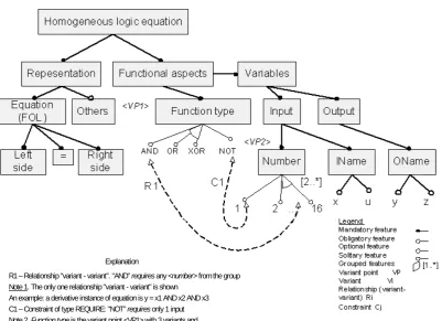
Figure 3. FD as a domain model instantiated from its meta-model
The assumptions are as follows:
1. Analysis of meta-model entities and identification whether all entities have been included in the meta-model.
2. Checking of the relationships and identification of the following situations:
a) Are there omitted relationships?
b) Is there no redundancy within relationships?
Explanation
R1 – Relationship "variant - variant". "AND" requires any <number> from the group Note 1. The only one relationship "variant - variant" is shown
An example: a derivative instance of equation is y = x1 AND x2 AND x3 C1 – Constraint of type REQUIRE: "NOT" requires only 1 input Note 2. Function type is the variant point <VP1> with 3 variants and
Input number is the variant point <VP2> with 16 variants one is a
c) Is the given relationship of a correct type? 3. Checking of the correctness of relationship
car-dinalities.
4. Checking of the correctness of the constraints.
3.4. Instances of FD meta-model
The model instantiation in the model-driven ap-proach is a vertical process of lowering the abstraction level, when we start from the higher-level model and create its lower-level representation until the level suitable for implementation is reached. For example, the result of the instantiation of the problem domain meta-model in our context is the creation of a concrete FD for the given application. Therefore, to perform the instantiation, first, we need to introduce the prob-lem (or application) domain. Two aspects are impor-tant to focus in that case.
If we assume that the problem domain is a priori known for both the analyst and the meta-designer, the first aspect is the identification of the scope for that domain. More precisely, the identification of scope means dealing with two tasks: a) specifying domain boundaries (i.e., what is within and what is outside of the domain); and b) specifying requirements, includ-ing requirements for change. These tasks are to be solved by the domain analyst, perhaps, with the pos-sible partial involvement of the meta-designer. The result of the scope identification should be expressed through features. As it is not an easy task one can consider initially the “reduced scope”, i.e. a sub-do-main of the selected dosub-do-main, and later extend the domain model based on the evolving FD diagram, we propose in [28, 29].
The second aspect is to draw a FD that conforms to its meta-model (Figure 2). Checking correctness of the FD instantiation from its meta-model includes the following: a) checking whether or not the FD is de-picted according to the pre-specified syntax (a full syntax of FDs as a graphical notation is given in [20]); b) checking semantics of the FD, i.e. validation of representing requirements for change and constraints. As requirements for change express domain variability and evolution, some difficulties may arise in order to perform the checking procedure. As a result, a meta-designer needs to build and consider a few variants of FDs. These variants can be treated as an evolution model describing a family of instances of the related FDs. We illustrate the instantiation process and present a FD as an instantiated model instance. Consider, for example, the entire domain of homogeneous logic equations (in terms of the prescribed requirements) for
the efficient derivation (when implemented) of any
instance of the equation. The domain is represented by its model given as a FD in Figure 3 (for details, read the explanation and legend within Figure 3). It de-scribes basically all the properties depicted in meta-model (see Figure 2).
Though, in this paper, it is not our intention to describe in detail the instantiation process for deriving
the FD instances from the FD meta-model (this problem requires the separate investigation), we provide some useful observations on this account below.
1. The formal use of the FD meta-model (Figure 2) is not enough for achieving the goal, i.e. for creating FD instances. A domain analyzer, first, should understand the domain under consideration well; and next, he/she needs to apply well-formed principles for representing the domain model, when it is derived from its meta-model.
2. The basic principle we have used implicitly for creating the model in Figure 3 is separation of
concepts (also the relevant terms, such as aspects
or features, may also be used). The use of the
principle is governed by the assumption that con-cerns are orthogonal (i.e. independent or not cross-cutting). Another important item is as follows:
when to start applying the principle for some con-cept in the decomposition process, either as early as possible (i.e., at a higher level) or as late as possible (i.e., at a lower level)? Depending on that, we can derive instances having the different struc-ture (syntax) but the same functionality (seman-tics).
For example, we have introduced the concern <functional aspects> as early as possible while const-ructing the FD instance (see Figure 3). However, it was possible to introduce the concern later after con-sidering the concept <right side>. If applied, that would imply receiving another configuration of the FD instance with the same functionality. Now one can easily reconstruct the instance and receive another shape of the instance.
Yet another remark is important to outline: consti-tuents of the feature model (see Figure 3) are also treated as elements or patterns of the model (see also Figure 1). Though all types of elements are important to form transformation rules, however, constraints and variant points have the highest priority when trans-forming the model into meta-program. This property can be easily disclosed by comparing the model (Fi-gure 3) with the presented example in Section 4 (see Figure 7).
3.5. Meta-model of meta-program
from parameters that are described using meta-constructs derived from a meta-language. The <meta-body> is constructed from two parts: modification/ change model and program instance model. The latter is derived from a domain language.
The structure of the meta-model should be inter-preted as follows. All entities in the description (see Figure 4) are abstractions of the solution domain, i.e. meta-programming per se. By adding the word model
to any entity, we intend to specify any entity of its kind, but not its concrete instance. For example, the modification/change model describes all possible changes within the meta-model. A set of domain lan-guages means that a concrete domain language is not specified at this level, yet. The same relates to languages. We consider the instantiation of the meta-model in the next sub-section.
Figure 4. Specification of meta-program meta-model
Figure 5. Instance of meta-program model derived from its meta-model
3.6. Instance of the meta-program meta-model
The model instance is created through the instan-tiation process using the meta-model that is one level higher then the instance model itself. The instance of the meta-program meta-model is given in Figure 5. This description differs from the previous one (see Figure 4) in the following: a) a concrete domain
instance, meta-parameters and meta-interface are also concretized in the same way.
In order to create an instance of a modification algorithm, however, we need to know requirements for change. Though the requirements are formulated by the user or/and domain analyst at the level that is higher than the meta-program model, we have inclu-ded requirements for change in the description of the model for clearness.
3.7. Elements of the instance of meta-program meta-model
The elements of a meta-program are derived from the meta-program model through the instantiation process in the same way as the meta-program model is derived from its meta-model. As we can see in Figure 5, there are two basic elements: meta-interface and body. For simplicity, we assume that a program contains only one interface and meta-body. Each element has its internal structure. When the structure is of interest in a predefined context, one can identify the constituent parts of the element. For example, meta-interface contains a set of meta-para-meters. Meta-body consists of a set of domain prog-ram instances that are represented using the domain language. A program instance has its own interface and functionality. The program instance has specific locations specified where change can be applied. What level of granularity is to be achieved in the elements
elicitation is the matter related to the transformation rules that should describe how input elements are transformed or merged into target elements.
4. Interpretation of transformations within the framework
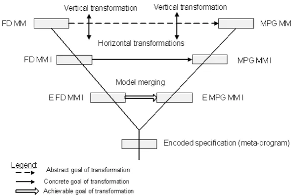
So far we have considered transformations of the problem domain abstractions and solution domain abstractions separately. Those transformations have been called model instantiations. Model instantiation is a vertical transformation aiming to derive a lower-level model from its meta-model. Here we describe all transformations very abstractly without details. Figure 6 outlines the view to all transformations, as they should be conceived using the framework.
At the beginning, the abstract goal for transfor-mations at the highest level, that is, at the meta-model level is specified. As the abstract goal is not achiev-able, one needs to make the lowering of abstraction level by one step (level) moving in the vertical direc-tion in each branch of the Y-chart. The result of such a vertical transformation is the creation of meta-model instances for both domains. Having the models ins-tances we can narrow the abstract goal transforming it into the achievable goal (in Figure 6 it is denoted by the single line). Though the goal may be achievable the practical mechanism of its implementation is yet not devised.
Figure 6. Abstract interpretation of transformations in meta-program development framework
Therefore, we need to make yet another step of horizontal transformation for transforming models in-to constituent elements in each branch. Again, the achievable goal is transformed through a vertical transformation into the concrete goal that can be al-ready implemented by transformation rules for each kind of model elements. Note that the definition of
transformation rules is not the intention of the frame-work.
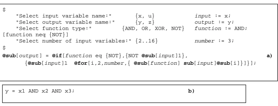
such a transformation. The example (Figure 7) out-lines the implementation of the FD depicted in Figure 3, using Open PROMOL [30] as a meta-language, and logical equations in plain text as a domain language.
Note that names of external meta-parameters are given in italic and Open PROMOL functions are given in bold (see Figure 7).
Figure 7. Encoding of FD given in Figure 3 using Open PROMOL (a); (b) one of derivative instances
5. Requirements for tools to support (semi-) automatic development of meta-programs
In terms of the OMG approach, a transformation is the process that should be performed automatically by adequate tools. In general, however, this maturity level of design technologies is still not achieved, but we can assume that the creation of meta-programs automati-cally for some specific cases with some prescribed assumptions might be considered as a real scientific task already now. We analyze those cases and assump-tions and formulate requirements for tools to support automation of meta-program development as follows: 1. Well-defined syntax and semantic of FDs.
2. Tools for automatic or semi-automatic drawing of FD.
3. Automatic validation of correctness of feature mo-dels.
4. Automatic decomposition of a feature model into sub-models with respect to prescribed require-ments.
5. Well-defined formalism to specify requirements for change.
6. Well-defined transformation rules to support trans-formation of the feature-based model specification into the meta-program specification.
7. Support of meta-language processors (depending on the application domains).
8. Support of different domain language compilers, domain program analyzers and parsers (depending on the application domains).
6. Summary and conclusions
We have proposed a general framework for the model-driven analysis of processes related with meta-program design. Abstractly, the meta-meta-program design framework can be represented as the Y-chart.
Branches of the chart represent three important items: problem domain (left branch), solution domain (right branch) and the result of their linking, i.e., the de-veloped meta-program (vertical branch). We represent problem domain and solution domain at three abstrac-tion levels: meta-model, model and instance. By the problem domain, we mean abstractions used to repre-sent domain models. By the solution domain, we mean programming abstractions (languages and meta-models, meta-models, etc.). We have selected the feature-based abstraction (i.e., Feature Diagram) to specify and represent domain models because it allows ex-pressing functional, structural behavioral aspects in terms of feature variability and commonality relationships explicitly and precisely; furthermore, those relationships are captured intuitively and simply.
The important aspect of the model-driven analysis of meta-programming, or how meta-programs should be devised using a transformative approach, is the traversing across the abstraction levels within the branches of the Y-chart. The traversing starts at the highest abstraction level in the right branch, and can be interpreted as either horizontal or vertical transfor-mation. The intention of the horizontal transformation is to achieve the abstract goal (i.e., to check a pos-sibility to combine domains) at the highest abstraction level. If at this abstraction level there is no enough information about model elements to derive transformation rules in order to perform the horizontal transformation, a meta-designer needs to go through a series of vertical transformations to lower the abstrac-tion level and to consider more details within the model representations. Vertical transformation is the
model instantiation process, when lower-level models
or their elements are derived from their meta-models. Vertical transformation in both the left and the right branch of the Y-chart is performed step-by-step that leads to lowering of the abstraction level by one consecutive level.
$
"Select input variable name:" {x, u} input := x; "Select output variable name:" {y, z} output := y; "Select function type:" {AND, OR, XOR, NOT} function := AND; [function neq {NOT}]
"Select number of input variables:" {2..16} number := 3; $
@sub[output] = @if[function eq {NOT},{NOT @sub[input]1}, a)
{@sub[input]1 @for[i,2,number,{ @sub[function] sub[input]@sub[i]}]}];
At the lowest level, i.e. at the model element repre-sentation level, we can already formulate and preci-sely express transformation rules stating how to merge (i.e. to transform) model elements of problem and solution domains. Though we have not yet presented those rules explicitly (that will be a subject of further work), the introduced framework gives a solid theore-tical background to understand the meta-program de-velopment process and also contributes to the auto-mation of this process per se. We have also formulated requirements for tools to support the automation.
The introduced framework enables: 1) to better understand the meta-program development process using the model-driven approach; 2) to identify some essential aspects of model-driven transformations, such as reachability of goals in horizontal transfor-mation, or the property to induce the multiple repre-sentation forms of the feature diagram instance with the same semantics for the same domain task, when the instance is instantiated from its meta-model in the vertical transformation. As a result, the discussed framework creates well-founded pre-conditions to de-velop a model transformation-based approach to the semi-automatic construction of meta-programs.
References
[1] D.C. Schmidt. Model-Driven Engineering. IEEE Computer 39 (2): 2006, 25-31.
[2] J. Bosch. Design and use of software architectures: adopting and evolving a product–line approach.
Addi-son-Wesley, 2000.
[3] G. Butler, D.S. Batory, K. Czarnecki, U.W. Eisene-cker. Generative Techniques for Product Lines. Proc. of the 23rd Int. Conf. on Software Engineering, ICSE 2001, 12-19 May 2001, Toronto, Ontario, Canada, 2001, 760-761.
[4] OMG. MDA Guide Version 1.0.1, 2003. Version 1.0.1, OMG document omg/03-06-01.
[5] R. Damaševičius, V. Štuikys. Taxonomy of the Fun-damental Concepts of Metaprogramming. Information
Technology and Control, 37(2), 2008, 124-132. [6] V. Štuikys, M. Montvilas, R. Damaševičius.
Deve-lopment of WEB Component Generators Using One-Stage Metaprogramming. Information Technology and
Control, 38(2), 2009, 108-118.
[7] D. Batory. Multilevel Models in Model-Driven En-gineering, Product Lines, and Metaprogramming. IBM
Systems Journal, 45(3), 2006, 527–539.
[8] S. Trujillo, D.S. Batory, O. Díaz. Feature-Oriented Model Driven Development: A Case Study for Port-lets. Proc. of 29th Int. Conf. on Software Engineering (ICSE 2007), Minneapolis, MN, USA, May 20-26, 2007, 44-53.
[9] W. Mueller, Y. Vanderperren. UML and Model-dri-ven Development for SoC Design. Proc. of the 4th Int.
Conf. on Hardware/Software Codesign and System Synthesis (CODES+ISSS’06), 22-25 Oct. 2006, 1. [10] P. Hruby. Mapping Business Processes to Software
Design Artifacts. In S. Demeyer, J. Bosch (Eds.):
Proc. of Object-Oriented Technology, ECOOP'98
Workshop Reader, Brussels, Belgium, July 20-24, 1998. LNCS 1543, Springer 1998, 234-236.
[11] A.G. Kleppe, J. Warmer, W. Bast. MDA Explained, The Model-Driven Architecture: Practice and Promise.
Addison Wesley, 2003.
[12] T. Mens, K. Czarnecki, P. Van Gorp. A Taxonomy of Model Transformations. Electronic Notes in Theo-retical Computer Science, Vol.152, 2006, 125-142. [13] L. Grunske, L. Geiger, A. Zundorf, N. Van
Eetvel-de, P. Van Gorp, D. Varro. Using Graph Trans-formation for Practical Model-Driven Software Engineering. In S. Beydeda, M. Book, V. Gruhn, eds.,
Model-Driven Software Development, Springer, 2006, 91-118.
[14] M. Janota, J. Kiniry. Reasoning about Feature Mo-dels in Higher-Order Logic. Proc. of 11th Int. Conf. on
Software Product Lines, SPLC 2007, Kyoto, Japan,
September 10-14, 2007, 13-22.
[15] B. Westfechtel, R. Conradi. Multi-Variant Modeling Concepts, Issues and Challenges. European Confe-rence on Model-Driven Architecture (ECMDA),
Twen-te, The Netherlands, June 24, 2009, 57-67.
[16] P. Ebraert, A. Classen, P. Heymans, T. D’Hondt. Feature Diagrams for Change-Oriented Programming.
Proc. of the 10th Int. Conf. on Feature Interactions in
Software and Communication Systems (ICFI’09), Lis-bon, Portugal, June, 2009. IOS Press, 2009, 107-122. [17] T. Ziadi, J.M. Jezequel, Product Line Engineering
with the UML: Deriving Products. In: Software
Product Lines, Springer, 2006, 557-586.
[18] G. Perrouin, J. Klein, N. Guel, J.M. Jezequel. Re-conciling automation and extensibility in product deri-vation. Proc. of 12th Int. Software Product Line
Conference (SPLC 2008), Limerick, Ireland, 339-348. [19] J. Coplien, D. Hoffman, D. Weiss. Commonality and
Variability in Software Engineering, IEEE Software, 15: 1998, 37-45.
[20] P.-Y. Schobbens, P. Heymans, J.-Ch. Trigaux, Y. Bontemps. Feature Diagrams: A Survey and a Formal Semantics. 14th IEEE Int. Requirements Engineering
Conference (RE'06), Minneapolis, Minnesota, USA,
September 2006, 139–148.
[21] V. Štuikys, R. Damaševičius. Measuring Complexity of Domain Models Represented by Feature Diagrams.
Information Technology and Control, 38(3), 2009, 179-187.
[22] D.D. Gajski, R.H. Kuhn. Guest Editor’s Introduction: New VLSI Tools. IEEE Computer, December 1983, 11-14.
[23] T. von der Massen, H. Lichter. RequiLine: A Re-quirements Engineering Tool for Software Product Lines. Proc. of Software Product-Family Engineering,
PFE 2003, Siena, Italy, Lecture Notes in Computer
Science (LNCS), 3014, 168-180.
[24] K. Czarnecki, S. Helsen, U. Eisenecker. Staged Configuration through Specialization and Multi-Level Configuration of Feature Models. Software Process
Improvement and Practice, 10, 2005, 143-169. [25] M.A. Laguna, J.M. Corral. Feature Diagrams and
their Transformations: an Extensible Meta-model.
Proc. of 35th Euromicro Conf. on Software
Enginee-ring and Advanced Applications, SEAA 2009, Patras,
[26] B. Morin, G. Perrouin, P. Lahire, O. Barais, G. Vanwormhoudt, J.-M. Jézéquel. Weaving Variabili-ty into Domain Metamodels. In A. Schürr, B. Selic (Eds.): Proc. of 12th Int. Conf. on Model Driven
En-gineering Languages and Systems, MODELS 2009,
Denver, CO, USA, October 4-9, 2009. LNCS 5795
Springer 2009, 690-705.
[27] P. Heymans, P.-Y. Schobbens, J.-C. Trigaux, R. Matulevičius, A. Classen, Y. Bontemps. Towards the Comparative Evaluation of Feature Diagram Lan-guages. Proc. of the Software and Services Variability
Management Workshop – Concepts, Models and Tools
(SVM-WS 2007), Helsinki, Finland, April 2007, 1-16. [28] R. Damaševičius, V. Štuikys, E. Toldinas. Domain
Ontology-Based Generative Component Design Using Feature Diagrams and Meta-Programming Techni-ques. Proc. of 2nd European Conference on Software
Architecture ECSA 2008, September 29 - October 1,
Paphos, Cyprus. ECSA 2008, LNCS 5292,
Springer-Verlag, 2008, 338-341.
[29] V. Štuikys, R. Damaševičius. Design of Domain On-tology-Based Generative Components Using Enriched Feature Diagrams and Meta-Programming.
Informa-tion Technology and Control, 37(4), 2008, 301-310. [30] V. Štuikys, R. Damaševičius, G. Ziberkas. Open
PROMOL: An Experimental Language for Target Program Modification. In A. Mignotte, E. Villar, L.
Horobin (Eds.), System on Chip Design Languages. Kluwer Academic Publishers, 2002, 235-246.