Design of Smart home System Based on Basic Radio
Frequency Wireless Sensor Network
https://doi.org/10.3991/ijoe.v14i04.8389
Fang Tian!!"
Hunan Institute of Science and Technology, Yueyang, China [email protected]
Xi Long
Power China Zhongnan Engineering Co. Ltd., Changsha, China
Wendi Liao
Dongguan Advanced Technology Research Institute, Dongguan, China
Abstract—This paper attempts to integrate the wireless sensor network (WSN) into the smart home system. To this end, a smart home system was de-veloped based on the basic radio frequency (RF) WSN. First, the author intro-duced the architecture, nodes and features of the WSN. Then, the design pro-cess of the smart home system was detailed. The hardware of the system con-sists of such three parts as the master control, wireless transceiver and sensor terminal; the software of the system includes the basic-RF WSN program and the master module STM32 programme. After that, the established system was applied to temperature collection and control. The results show that the collect-ed temperature agrecollect-ed well with the temperature measurcollect-ed by the thermometer. Finally, the temperature control effect of the system was successfully simulated with a potentiometer and an LED lamp. The research findings shed new light on the design of smart homes.
Keywords—Wireless sensor network (WSN), smart home, basic radio frequen-cy (RF), STM32
1
Introduction
wired communication network [2-4]. In particular, the WSN supports multi-hop group monitoring of devices, and real-time processing of the monitored information [5]. Suffice it to say that the WSN opens up a new research field to scholars at home and abroad [6, 7].
One of the potential application fields of the WSN is the innovative concept of smart home. The concept was first proposed in developed countries like the US, Can-ada, and Australia [8, 9, 10]. Nowadays, smart home is increasingly accepted by those in pursuit of a convenient lifestyle [11, 12]. Traditionally, the smart home system is grounded on a wired home network, which is costly and hard to maintain. Coupled with remote control technology, the WSN is being integrated into the smart home system. This move greatly enhances the flexibility, stability and scalability of the home network [13, 14].
The smart home industry started early and developed fast in foreign countries. Many famous companies have set foot in this field, namely Honeywell and Control4. The latest information technology has been harnessed to create a safe, comfortable and convenient living environment for ordinary people [15, 16]. For instance, the Control4 smart home system can be configured flexibly according to their personal needs [17, 18]. In China, however, the smart home industry has just entered the appli-cation stage.
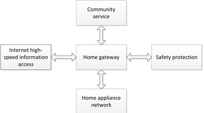
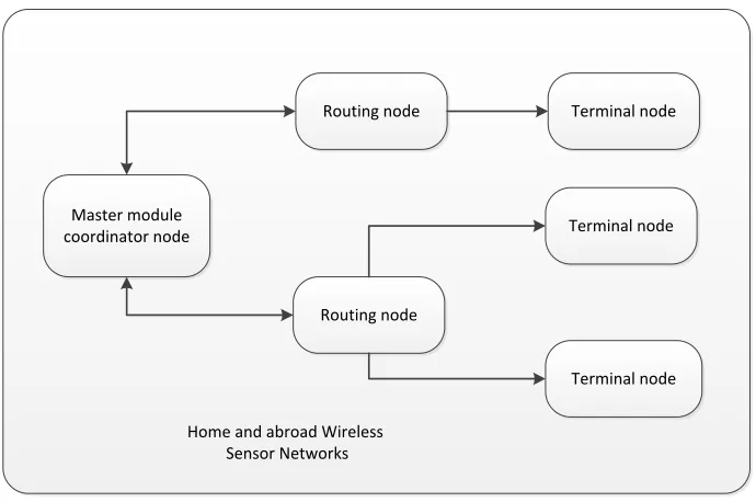
In general, a smart home consists of three components: the extranet, the intranet and the gateway. The extranet may be a residential LAN, a CCTV or a telephone network, most of which rely on mature technologies. The intranet is the LAN that links up all kinds of home devices. The form of the intranet varies with the devices in it. The gateway connects the intranet to the extranet, allowing the extranet to control the networked appliances. Besides, the gateway supports different networking tech-nologies so that the networked devices in each subnet can communicate with each other. The architecture of a smart home system is shown in Figure 1.
!"#$%&'($)'* +,($-,$(%./&.0
12$$3%/,4"-#'(/",% '55$11
6"##7,/(*% 1$-8/5$
!"#$%'229/',5$% ,$()"-:
;'4$(*%2-"($5(/",
In light of the above, this paper designs a smart home system based on the basic radio frequency (RF) WSN. First, the author introduced the architecture, nodes and features of the WSN. Then, the design process of the smart home system was detailed. After that, the established system was applied to temperature collection and control. The results show that the collected temperature agreed well with the temperature measured by the thermometer. Finally, the temperature control effect of the system was successfully simulated with a potentiometer and an LED lamp.
2
Principles and Characteristics of Wireless Sensor Network
2.1 WSN Architecture
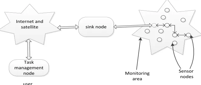
The WSN system mainly consists of three parts, namely sensor nodes, sink node and task management node. Each part has its own function. A great number of sensor nodes are distributed in the monitoring area and the wireless communication network transmits data to the sink nodes in a self-organized way. After receiving the sensor data transmitted by the network nodes, the sink node forwards the data to the task management node through an extranet, such as a satellite communication network. The task management node can monitor the operations in the area through terminal display, and also manage the sensor network remotely.
The architecture of the wireless sensor network is shown in Figure 2.
!"#$% &"'"()&)'*%
'+,)
#-'$%'+,) .'*)/')*%"',%
#"*)00-*)
1#)/
2+'-*+/-'(% "/)"
3)'#+/ %'+,)#
Fig. 2. Wireless sensor network architecture
sensi-tive areas. It can also send control commands to configure and manage the entire sensor network.
2.2 WSN node structure
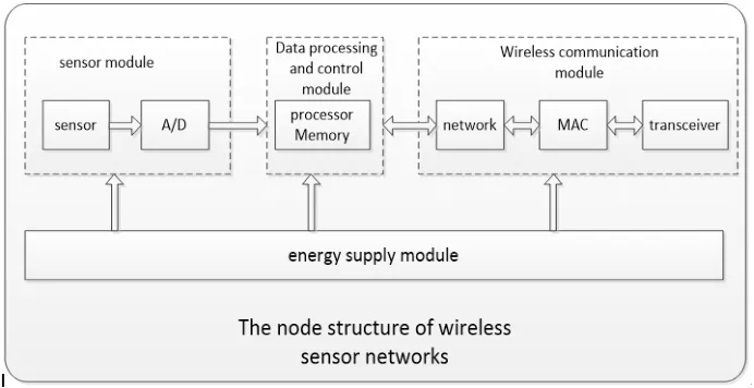
A sensor node is a tiny embedded system with data processing, storage and wire-less communication capabilities. It is composed of four parts - sensor module, proces-sor module, wireless communication module and power supply module. The structure of the node is shown in Figure 3. The nodes acquire the environmental parameters in the monitoring area by collecting the data of the sensors, and the processor module processes and stores the sensor data. The processed data are transmitted to the sink node one by one through the wireless communication module, and the energy module provides the power for the normal operation of the nodes. With tiny batteries, the nodes generally consume very low power to ensure that nodes can run for a long time.
Fig. 3. Node structure of the wireless sensor network
2.3 Characteristics of Wireless Sensor Network
A wireless sensor network has the following characteristics:
1.Large-scale network. Nodes are widely distributed in the monitoring area, which can improve the monitoring accuracy through the data fusion algorithm. The nodes are densely deployed in the monitoring area and thus can monitor large geograph-ical areas. Therefore, WSN is a large-scale network.
2. Ad hoc network. In a WSN, the locations of nodes are uncertain. Nodes may be distributed through random seeding in the monitoring area, so it is necessary for nodes to form their own network and then transmit data over the network.
4.Reliable network. Sensor nodes are randomly distributed in the monitoring area, so network nodes need to run reliably and cannot be easily damaged, and the data transmission nodes should have a series of reliable response mechanisms to guar-antee reliable transmission in the monitoring data.
5.Data Centre network. The communication between nodes in a wireless sensor work is based on the data transmission in the network. The object of sensor net-work monitoring is uncertain, and the nodes are identified in the netnet-work through data interaction.
3
Hardware Design
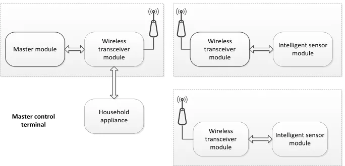
The design of a smart home system based on WSN mainly involves three parts - sensors acquiring data, wireless transceiver chips sending or receiving data and com-mands, and the master chip processing data. This system is mainly composed of two parts - master control and sensor terminals. The master control terminal is used to receive and analyse the data of the sensor terminals, and the sensor terminal is used to acquire and transmit data. The functions of the master control are realised by the mas-ter control module and the wireless transceiver module, and the functions of sensor terminals are completed by the wireless transceiver module and the smart sensor module.
The hardware design of the smart home system is shown in Figure 4.
!"#$%&'()*+,%
-)+#%.),*' "//,0"12%
30&%,%##' $&"1#2%04%&'
()*+,%
30&%,%##' $&"1#2%04%&'
()*+,%
51$%,,06%1$'#%1#)&' ()*+,%
30&%,%##' $&"1#2%04%&'
()*+,%
51$%,,06%1$'#%1#)&' ()*+,% !"#$%&'()*$&)+'
$%&,-*"+
Fig. 4. Block diagram of the smart home system hardware
3.1 Master control design
analyse the processing instructions to or from the sensor terminals. The master control module coordinates other modules, so that the whole system can run in an orderly fashion, and also to analyse and process the acquired data. It can also connect with the computer, write the programme into the MCU with the help of the development envi-ronment, display the data and information acquired by sensors, and select the func-tions of the system. The data processing chip of the master control module is STM32.
3.2 Wireless transceiver module design
The wireless transceiver module is composed of a wireless transceiver chip and an-tenna, etc. It is designed to carry out data transmission with a single chip microputer, receive and transmit the commands of the single chip commicroputer, send the com-mands to other sensor terminals, and acquire sensor terminal data. This module uses Nordic’s monolithic RF transceiver n RF905 as the wireless transceiver chip to re-ceive and transmit data or commands.
3.3 Sensor terminal design
The sensor terminal is composed of an intelligent sensor module and a wireless transceiver module. The sensor terminal is used for data acquisition and transmission. DS18B20 is used as the temperature sensor to collect temperature data. The MCU sends the collected data and displays them on the LCD screen. The humidity sensor HS1101 is used to collect humidity data. The MCU sends the collected data and dis-plays them on the LCD screen.
4
Software Programming
4.1 Program design of wireless sensor network based on Basic-RF
!"#$%&'()*+,%' -))&*./"$)&'/)*%
0)+$./1'/)*%
0)+$./1'/)*%
2%&(./",'/)*%
2%&(./",'/)*%
2%&(./",'/)*%
3)(%'"/*'"4&)"*'5.&%,%## '6%/#)&'7%$8)&9#
Fig. 5. Structure of the wireless sensor network
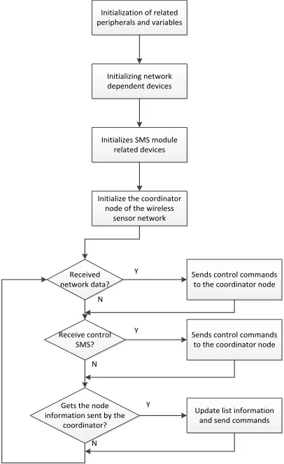
4.2 Programming of the master control module STM32
The master control module of the smart home is based on the STM32 microcon-troller, and the programme flow chart of the STM32 in the smart home system is shown in Figure 6.
5
Experiments and Result Analysis
5.1 Temperature measurement experiment
!"#$#%&#'%$#(")(*)+,&%$,-) .,+#./,+%&0)%"-)1%+#%2&,0
!"#$#%&#'#"3)",$4(+5) -,.,"-,"$)-,1#6,0
7,"-0)6("$+(&)6(88%"-0) $()$/,)6((+-#"%$(+)"(-, 7,"-0)6("$+(&)6(88%"-0)
$()$/,)6((+-#"%$(+)"(-, !"#$#%&#',0)797)8(-:&,)
+,&%$,-)-,1#6,0
!"#$#%&#',)$/,)6((+-#"%$(+) "(-,)(*)$/,)4#+,&,00)
0,"0(+)",$4(+5
;.-%$,)�$)#"*(+8%$#(") %"-)0,"-)6(88%"-0 <,6,#1,-)
",$4(+5)-%$%=
<,6,#1,)6("$+(&) 797=
>,$0)$/,)"(-,) #"*(+8%$#(")0,"$)2?)$/,)
6((+-#"%$(+= @
@
@ A
A
A
Fig. 6. Program flow chart of the master control module STM32 in the smart home system
!" # " $ % & '# '" '$ '%
' " ( $ ) % * & + '#
!"#$"%&!'%"(
)"*!+*"%,&-+.'#/"%
)0"%#1#"!"%+ !"#$"%&!'%"
23*!"#+ !"#$"%&!'%"+ #"&*'%"#".!+ "%%1%
Table 1. Temperature acquisition data
Test serial number Thermometer temperature System temperature measurement error
1 12.0 12.6 0.6
2 11.5 11.3 -0.2
3 13.0 13.2 0.2
4 13.4 13.3 0.3
5 12.5 12.6 0.1
6 12.0 12.5 0.5
7 13.6 13.1 -0.5
8 12.4 12.1 -0.3
9 13.5 13.9 0.4
10 11.7 12.2 0.5
5.2 Temperature control experiment
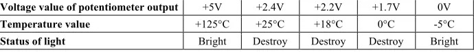
In the experiment, because the temperature measured in a day changes little, and cannot help achieve control, the author uses a potentiometer to simulate the changes of temperature Through adjustment of the potentiometer, the outputs of different voltages represent different temperatures. By common sense, the best living environ-ment for people is 18 to 25°C; otherwise people will feel uncomfortable. In the test, a light emitting diode is used to indicate the temperature control signals, and the diode emits light when the temperature simulated by the potentiometer exceeds the set point. The relationship between temperature and status of light is shown in Table 2.
Table 2. Relationship between temperature and status of light
Voltage value of potentiometer output +5V +2.4V +2.2V +1.7V 0V Temperature value +125°C +25°C +18°C 0°C -5°C Status of light Bright Destroy Destroy Destroy Bright
6
Conclusions
7
Acknowledgment
This work is supported by Dongguan social science and technology development project (2017507102427), Science Research Project of Hunan Institute of Engineering (YY1720, XJ1606).
8
References
[1]Gu, Y.C., Kong, Y., Chen, R.H. (2002). Development and trend of sensor technology.
Physics experiment, 22(12), 40-42.
[2]Zhang, W. (2006). Research on smart home applications based on wireless sensor
net-works. Master's thesis, Xi'an: Northwestern Polytechnical University.
[3]Xia, F. (2009). Research on wireless sensor network nodes based on Z Stack protocol.
Ap-plication of electronic components, 11(12), 74-76.
[4]Chen, S.J. (2005). Research on wireless smart home control network design and protocol.
Master's thesis, Dalian: Dalian Maritime University.
[5]Pan, H., Chao, J. (2010). Application of wireless sensor network in information home
net-work control system. Digital technology and application, 7.
[6]Byrne, J.A. (1999). 21 Ideas for the 21st Century. Business Week, 8, 78-167.
[7]Terry, J. (2003). 10 Emerging Technologies that Will Change the World. Technology
Re-view, 106(1), 33-49.
[8]Wang, B., Lan, Y., Liu, X.P. (2006). Development and Prospects of network appliance
technology. Application of electronic technology, (7), 1-5.
[9]Xiong, G., Wang, Z., Zhang, X., Ji, G. (2012). Design and implementation of real time
terminal for home association. Measurement and control technology, 31(3), 80-85.
[10]Chen, C.Y., Zhu, L., Ma, X. (2006). Research and design of modern smart home. Forestry
machinery and woodworking equipment, 34(4), 6-8.
[11]Jin, C.H., Cheng, D. (2005). Home networking technology for smart home research.
Intel-ligent building and city information, (10). 33-38.
[12]Xu, Q. (2010). Analysis of the development and research status of smart home appliances.
Modern business industry, 22(008), 101-102
[13]Wang, Z., Chen, D., Huang, G., Tong, H. (2012). Research and implementation of smart
home system based on Android. Computer technology and development, 22 (6), 225-228
[14]Man, S., Yang, H.X., Peng, Y., Wang, X.S. (2010). Design of embedded wireless smart
home gateway based on ARM9. Jisuanji Yingyong/ Journal of Computer Applications,
30(9), 2541-2544. https://doi.org/10.3724/SP.J.1087.2010.02541
[15]Zheng, J., Wu, C., Zhang, J. (2004). Application of personal LAN based on Bluetooth
technology in smart home. Architectural intelligence, (8), 25-29.
[16]Gong, J., Liu, Q., Liu, J. (2002). Application of artificial intelligence in elevator group
control system. Journal of Shenyang Institute of Architectural Engineering (NATURAL SCIENCE EDITION), 18(4), 306- 308.
[17]Asim, M., Mokhtar, H., Merabti, M. (2009). A cellular approach to fault detection and
re-covery in wireless sensor networks. Computer science, 5(1), 352-357.
https://doi.org/10.1109/SENSORCOMM.2009.61
[18]Ji, S., Yuan, S., Ma, T., Tian, Wei. (2010). Method of fault detection for wireless sensor
9
Authors
Fang Tian, Master graduate, lecturer, Inauguration in Hunan Institute of Science and Technology, Yueyang 414000, China, research direction of Internet of things technology research ([email protected]).
Xi Long, Engineers, Inauguration in Power china Zhongnan Engineering Co. Ltd, mainly from things networking technology.
Wendi Liao, Doctor, Inauguration in Dongguan Advanced Technology Research Institute, Dongguan 523808, China, mainly engaged in measurement and control.