http://www.scirp.org/journal/jbise J. Biomedical Science and Engineering, 2019, Vol. 12, (No. 5), pp: 285-292
https://doi.org/10.4236/jbise.2019.125021 285 J. Biomedical Science and Engineering
Compression Test and Finite Element Analysis for Failure
Criterion of the Tibial Post of a Posterior-Stabilized Knee
Prosthesis
Rina Sakai1 , Urabe Ken2, Kazuhiro Yoshida1, Kiyoshi Mabuchi1, Masanobu Ujihira1
1Department of Biomedical Engineering and Technology, School of Allied Health Sciences, Kitasato University, Sagamihara, Japan; 2Department of Orthopedic Surgery, Kitasato University Medical Center, Kitamoto, Japan Correspondence to: R. Sakai,
Keywords: Proximal Humeral Fracture, Retrograde Intramedullary Nailing, Anterograde Intramedullary Nailing, Locking Plate, Internal Fixation
Received: April 15, 2019 Accepted: May 18, 2019 Published: May 21, 2019 Copyright © 2019 by authors and Scientific Research Publishing Inc.
This work is licensed under the Creative Commons Attribution International License (CC BY 4.0). http://creativecommons.org/licenses/by/4.0/
ABSTRACT
Post cam mechanism of Posterior Stabilized (PS) knee prostheses is useful to realize intrin-sic stability for cases with severe degeneration. However, some retrieval studies report se-vere failure of the polyethylene tibial post. We thought that sese-vere failures were caused by high loads during daily activities. In the current study, we performed a compression test and a finite element analysis of the mechanical forces produced in the tibial post in post-erior-stabilized knee prostheses in order to develop a specification for the tibial posts found in the polyethylene inserts of PS knee prostheses. Anterior tibial post impingement and posterior tibial post impingement were simulated. The surface pressure values detected in the compression test were consistent with those obtained in the FE analysis. Of the three designs, the lowest von Mises stress values were generated inside the round tibial post; therefore, tibial posts should be round. The risk of tibial post failure was low when 500 or 1000 N was loaded onto the knee joint. It was suggested that tibial post failure occurs when the shear strain at the base of the tibial post exceeds 0.1.
1. INTRODUCTION
Posterior-Stabilized (PS) knee prostheses are equipped with a post-cam structure in which the polye-thylene insert has a projection termed a post, which stabilizes the joint by joining with a cam of the femor-al component. This structure refemor-alizes anteroposterior stability and physiologicfemor-al flexion as an femor-alternate function of the posterior cruciate ligament after surgery, and favorable treatment outcomes were achieved. However, the occurrence of post breakage several years after surgery has often been reported [1-4].
https://doi.org/10.4236/jbise.2019.125021 286 J. Biomedical Science and Engineering
garding the cause, the procedure, such as abnormality of the angle set in surgery, has been discussed, but Chiu et al. reported a case in which placement failure was not confirmed but the post broke three years after surgery [5].
The cause of post breakage may be unexpectedly high stress loaded on the post. An index to design a safe post which does not break may be necessary, but there are no reports on this. Moreover, the amount and condition of weight-bearing which may cause breakage are also unclear. The post shape of commer-cially available PS-type knee prostheses varies among manufacturers. To identify a safe shape, it may be necessary to perform tests and numerical analysis of posts with different shapes under identical conditions and investigate an ideal shape based on the results.
In this study, posts of PS-type knee prostheses were subjected to a compression test and finite element analysis (FEA) on the assumption of mechanical conditions in the body to establish strength criteria for designing a shape.
2. MATERIALS AND METHODS
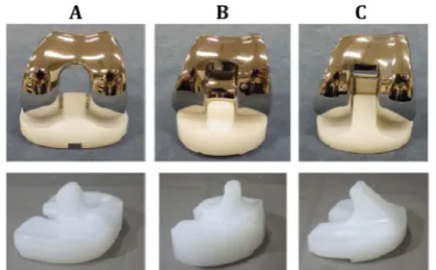
2.1. Compression TestsPS-type knee prostheses, A, B, and C, were prepared (Figure 1). The characteristics of the post are different: small flat (A), small curved (B), and large flat shapes (C), respectively.
[image:2.595.200.399.374.497.2]Pressure film (Prescale, Fujifilm, Japan) cut into an appropriate size was applied to the anterior or posterior surface of the post of the polyethylene insert of the three types. The compression test between the post and femoral component was performed (Figure 2). The maximum pressure [MPa] and pressurized area [mm2] were determined using a pressure image analysis system (FPD8010J, Fujifilm, Japan).
Figure 1. PS-type knee prostheses, A, B, and C.
[image:2.595.176.417.536.700.2]https://doi.org/10.4236/jbise.2019.125021 287 J. Biomedical Science and Engineering
Measurement was performed at two flexion angles: −10˚ and 120˚. It is known that the tibial surface internally rotates 5˚ - 10˚ against the femur in deep flexion, measurement was also performed at 120˚ flex-ion + 10˚ internal rotatflex-ion of the insert. The positflex-ion at −10˚ flexflex-ion simulated overextensflex-ion of the femur, reproducing impingement (collision) between the anterior surface of the post and femoral notch. The po-sitions at 120˚ flexion and 120˚ flexion + 10˚ internal rotation simulated deep flexion, reproducing im-pingement between the posterior surface of the post and femoral cam.
The femoral component and polyethylene insert were appropriately set, and forced displacement of a digital force gauge was applied at a speed of 20 mm/min to load on the post. The load was applied taking about 10 seconds, and displacement was stopped when the force reached500 N and held for 5 seconds.
At −10˚ flexion, bone cement was molded and attached to the anterior region of the femoral compo-nent. At 120˚ flexion, the epiphyseal region of the artificial femur (Femur with 11 mm Canal, #1129-19, SAWBONES, USA) was cut in the anteroposterior direction, and the distal cross-sectional surface was covered with bone cement and attached to the femoral component. At 120˚ flexion + 10˚ internal rotation, bone cement molded in a triangular prism shape with a 10˚ angle was placed between the anterior region of the polyethylene insert and the bottom plate of the tester to reproduce internal rotation of the tibial surface.
2.2. Finite Element Analysis
CT images of these knee prostheses were acquired, and DICOM data of each joint were collected. These data were read into image data processing software, using 3Dimage processing and preparation tool Scan IP (Simpleware, JSOL, Japan), and converted to STL data. The STL data of the femoral component and polyethylene insert were read-in using +CAD Module, and the positions and angle of the two parts were mutually adjusted so as to set the conditions identical to those of the measurements of the compres-sion test. These data were re-read-in using Scan IP, and meshes were prepared using the automatic mesh-ing function. Each element was constituted with a 4-node tetrahedron (Figure 3).
The prepared FE model was read-in using LS-prepost (TERRABYTE, Japan), and the material defini-tion and boundary, contact, and weight-bearing condidefini-tions were set. In the material definidefini-tion, the femoral component was prepared as a rigid model with a mass density of 8300 kg/m3, elastic modulus of 210 GPa, and Poisson’s ratio of 0.31. For the polyethylene insert, a poly-linear approximation isotropic elasto-plastic solid model with a mass density of 935 kg/m3, elastic modulus of 750 MPa, Poisson’s ratio of 0.37, and yield stress of 30 MPa was prepared. Poly-linear was referred to in literatures and defined as a material [6].
For the boundary conditions, displacement against the femoral component in all axes excluding the Y-axis and rotations in all axial directions were restricted, and the range of nodes on the bottom surface alone was specified against the polyethylene insert and completely restricted. For the contact, automatic contact was selected in consideration of slipping, and no gap element was used. The coefficients of static and mechanical frictions between the femoral component and polyethylene insert were set at 0.11 and 0.087, respectively. The loading condition was defined so as to load a specific weight on the entire femoral component, which is a rigid model, in the Y-axis direction. The load to be applied was set at 500 and 1000 N.
https://doi.org/10.4236/jbise.2019.125021 288 J. Biomedical Science and Engineering
For the analytical system, LS-DYNA ver. 971 (TERRABYTE, Japan) and Endeavor Pro-4500 (EPSON, Japan) were used for software and hardware, respectively. The data was output every one second. For the analytical time, 10-second pressurization and 5-second retention, a total of 15 seconds, were set. The pressure generated on the post surface and Von Mises equivalent stress and shear strain generated in the post by loading were analyzed and output.
3. RESULTS
3.1. Compression Tests
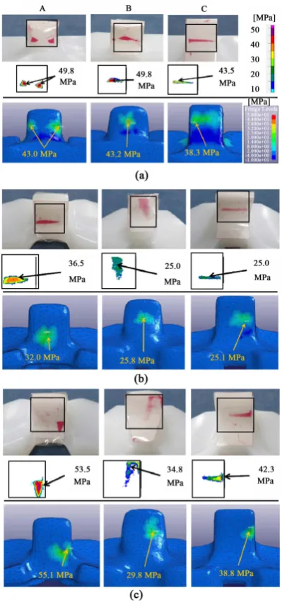
[image:4.595.198.398.246.673.2]At −10˚ flexion, the maximum pressures on the anterior surfaces of the posts of products A, B, and C were 49.8, 49.8, and 43.5 MPa, respectively (Figure 4(a), top), and the pressurized areas were 16, 20, and 23 mm2, respectively.
Figure 4. Surface pressure distribution. Top: Finite element analysis. Bottom: Pressure images were
https://doi.org/10.4236/jbise.2019.125021 289 J. Biomedical Science and Engineering
At 120˚ flexion, the maximum pressures on the anterior surfaces of the posts were 36.5, 25.0, and 25.5 MPa, respectively (Figure 4(b), top), and the pressurized areas were 18, 29, and 26 mm2, respectively.
The pressure distribution concentrated to the edge at 120˚ flexion + 10˚ internal rotation, compared with that at 120˚ flexion. The maximum pressures on the posterior surfaces of the posts were 53.5, 34.8, and 42.3 MPa (Figure 4(c), top), respectively, and the pressurized areas were 16, 33, and 23 mm2, respectively.
3.2. Finite Element Analysis
The maximum surface pressure and pressure distribution (Figure 4, bottom) loaded by 500 N on FEA were similar to the pressure distribution shown by the pressure film after the compression test, showing that the post-cam contact position was almost the same. The error from the maximum surface pressure on the compression test was within 15% in all products, showing that the values were consistent.
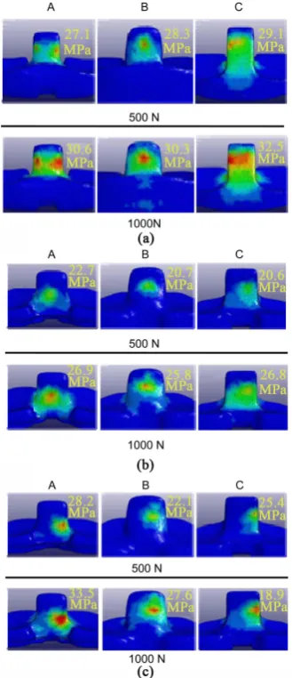
[image:5.595.216.381.303.685.2]The maximum value of Von Mises-equivalent stress loaded by 500 N was lower than the defined yield stress (30 MPa) under all measurement conditions in all products (Figure 5, Top). The stress level was relatively high at −10˚ flexion, whereas it was low at 120˚ flexion. The addition of internal rotation of the insert to 120˚ flexion increased stress on products A, B, and C by 24.2%, 6.8%, and 23.3%, respectively, showing that the rate of increase decreased in product B.
Figure 5. Von Mises-equivalent stress distribution. Top: 500 N. Bottom: 1000 N. (a) −10˚ flexion; (b)
https://doi.org/10.4236/jbise.2019.125021 290 J. Biomedical Science and Engineering
When 1000 N was loaded, Von Mises-equivalent stress (Figure 5, Bottom) exceeding the defined yield stress (30 MPa) was produced at −10˚ flexion in all three products and at 120˚ flexion + 10˚ internal rotation in product A. The rates of increase due to internal rotation of the insert were 24.5%, 3.0%, and 12.0% in products A, B, and C, respectively, showing that the increase rate was relatively high in product A and low in product B. The maximum value of 500 N load-induced shear strain was relatively high at −10˚ flexion in all three products, similar to Von Mises-equivalent stress. When 1000 N was loaded, shear strain exceeding 0.1 was produced at −10˚ flexion in all three products, and shear strain at 120˚ flexion + 10˚ in-ternal rotation was much higher in product A than in the other products.
4. DISCUSSION
Small plastic deformation on the femorotibial joint surface may be acceptable in designing strength of a knee prosthesis (plastic design) because force acting on the femorotibial joint surface is compressive and even a large load causes plastic deformation, reduction of true stress by an increase in the contact area can be expected. However, in the post-cam structure, although the compressive force acts on the contact point of the post, tensile and bending forces may act on the root of the post. When plastic deformation occurs in the root, the area joining the polyethylene insert and post immediately decreases and true stress increases, which may break the post. In reports on post breakage, most posts removed from the body were broken at the root, showing that stress loaded on the root of the post is important to investigate in post breakage. It was suggested that to design a safe post, stress against assumed loads should be lower than tensile and bending strengths, and this should be set as a criterion. In consideration of this, the yield stress of ul-tra-high-molecular-weight polyethylene as a material property was set at 30 MPa in the FEA [6].
The force levels acting on the anterior and posterior surfaces of posts have not been clarified, and there are only a few reports. Based on a study reporting that an about 100 N force was produced by contact between the anterior surface of the post and femoral component upon taking a step forward and placing the heel on the ground, Hamai et al. reproduced and measured this contact using a pressure sensor [7]. The flexion angle was −15˚ to 5˚ including overextension (knee extension exceeding 180˚). Li et al. deter-mined the force produced on the anterior surface of the post using knee joints of a robot and cadaver, and it was 252.4 ± 173.0 N at −9˚ [8]. This value shows a possibility of producing 400 N or higher force on the anterior surface of the post. Akasaki et al. loaded the femoral component with 500 N on the posterior sur-face of the post using a commercial PS-type artificial knee joint and determined the pressure produced [9]. Nakayama et al. reported an influence of internal rotation of the polyethylene insert under the same con-ditions [10]. Based on these findings, the measurement conditions of the mechanical test and FEA were set at −10˚ and 120˚ flexion, and 120˚ flexion + 10˚ internal rotation of the insert, and the load was set at 500 and 1000 N. Occurrence of 1000Nweight-bearing on the post in daily life is unlikely, but it may be neces-sary to consider its influence because recently some patients perform sports, such as golf and swimming, after artificial joint placement.
The maximum surface pressure loaded on the post on the mechanical experiment was consistent with the value on FEA, with a maximum error of 14.4%. Accordingly, the results of FEA may have been valid. On FEA, not only the surface pressure but also the Von Mises-equivalent stress and shear strain can be determined, and these cannot actually be measured. If the results of FEA are valid, these values may be reliable. Von Mises-equivalent stress is used as a yield index of materials for strength-designing, and it was considered appropriate to be used as a criterion of post breakage, which is the objective of this study.
https://doi.org/10.4236/jbise.2019.125021 291 J. Biomedical Science and Engineering
impingement at the anterior region of the post. When 1000 N was loaded, Von Mises-equivalent stress exceeding the yield stress was produced at −10˚ flexion in all products. However, stress exceeding 30 MPa was produced at the contact point between the post and cam, and stress produced at the root was about 10 MPa in all products. Assuming that plastic deformation at the contact point is acceptable to some extent, it is unlikely that 1000 N force loaded on the post causes breakage.
Considering the condition producing Von Mises-equivalent stress exceeding 30 MPa at the root of a post based on this, a force (3000 N) three times higher than this condition was loaded on the anterior sur-face of the post, i.e., a large load equivalent to this may have been loaded on the post in clinical cases of post breakage. Additional analysis is necessary to demonstrate this.
When 120˚ flexion and 120˚ flexion + 10˚ internal rotation were compared, differences due to the post shape were observed. Since the post and cam were flat-shaped in products A and C, internal rotation of the insert may have caused stress concentration on the edge of the post (edge loading). In product A, 120˚ flexion + 10˚ internal rotation also caused stress exceeding the defined yield stress of Von Mis-es-equivalent stress. However, Von MisMis-es-equivalent stress was produced at the post-cam contact point and due to a compressive force, this stress was considered unlikely to break the post.
On the other hand, no stress exceeding the yield stress was produced in products B and C, suggesting that the possibility of breakage of the posterior surface of the posts is low. In product B, since the post-cam shape is curved, even though internal rotation of the insert occurred, the contact area may not have mar-kedly decreased and the increase in stress induced by internal rotation of the insert may have decreased. In previous reports, stress production was smaller in the curve-shaped post-cam design than in the flat-shaped design, and our analysis obtained similar results. In addition, an inverse correlation (r = −0.75) was observed between the measured pressurized area and Von Mises-equivalent stress on analysis. Accor-dingly, an increase in the post-cam contact area reduces stress. It was suggested that to reduce the risk of breakage, a curved shape with high fit is important for the posterior surface of the post and cam of the fe-moral component, such as the post-cam in product B. Since Von Mises-equivalent stress of the post of product C was higher than that of product B, no advantage of a large size, such as product C, was con-firmed. Considering that the amount of osteotomy increases as the post volume increases and joint restric-tion also increases after surgery, the post volumes of products A and C may be sufficient.
5. CONCLUSION
Von Mises-equivalent stress and shear strain produced in the post of the commercial Post-erior-Stabilized-type knee prostheses were determined by performing compression test and finite element analysis. It is unlikely that a 1000 N force causes post breakage, but it may occur when a 3000 N force is loaded on the anterior surface of the post. It may be desirable that the post-cam shape is curved with high fit. When attention is paid to shear strain, the value was high when stress exceeded the yield stress (30 MPa), and the value exceeded 0.1 in all products, suggesting that when strain is employed as a criterion, a shear strain value of 0.1 may be applicable. It was assumed that post breakage occurs when shear strain at the root of the post exceeds 0.1.
ACKNOWLEDGEMENTS
This study was supported by the Kitasato University Research Grant for Young Researchers No. 2014-4008. We are grateful to Kensei Tanaka, Masaya Nakano, and Yuya Taira for their support.
CONFLICTS OF INTEREST
The authors declare no conflicts of interest regarding the publication of this paper.
REFERENCES
Stabi-https://doi.org/10.4236/jbise.2019.125021 292 J. Biomedical Science and Engineering lized Knee Prosthesis: A Case Report and Review of Literature. Journal of Orthopaedics, 12, 160-163.
https://doi.org/10.1016/j.jor.2015.01.002
2. Lim, H.C., Bae, J.H., Hwang, J.H., Kim, S.J. and Yoon, J.Y. (2009) Fracture of a Polyethylene Tibial Post in a Scorpio Posterior-Stabilized Knee Prosthesis. Clinics in Orthopedic Surgery, 1, 118-121.
https://doi.org/10.4055/cios.2009.1.2.118
3. Jung, K.A., Lee, S.C., Hwang, S.H. and Kim, S.M. (2008) Fracture of a Second-Generation Highly Cross-Linked UHMWPE Tibial Post in a Posterior-Stabilized Scorpio Knee System. Orthopedics, 31, 1137.
https://doi.org/10.3928/01477447-20081101-10
4. Bal, B.S., Greenberg, D., Li, S., Mauerhan, D.R., Schultz, L. and Cherry, K. (2008) Tibial Post Failures in a Con-dylar Posterior Cruciate Substituting Total Knee Arthroplasty. The Journal of Arthroplasty, 23, 650-655. https://doi.org/10.1016/j.arth.2007.08.002
5. Chiu, Y.S., Chen, W.M., Huang, C.K., Chiang, C.C. and Chen, T.H. (2004) Fracture of the Polyethylene Tibial Post in a NexGen Posterior-Stabilized Knee Prosthesis. The Journal of Arthroplasty, 19, 1045-1049.
https://doi.org/10.1016/j.arth.2004.04.013
6. Bartel, D.L., Rawlinson, J.J., Burstein, A.H., Ranawat, C.S. and Flynn, Jr., W.F. (1995) Stresses in Polyethylene Components of contemporary Total Knee Replacements. Clinical Orthopaedics Related Research, 317, 76-82. 7. Hamai, S., Miura, H., Matsuda, S., Shimoto, T., Higaki, H. and Iwamoto, Y. (2010) Contact Stress at the
Ante-rior Aspect of the Tibial Post in PosteAnte-rior-Stabilized Total Knee Replacement. The Journal of Bone and Joint
Surgery America, 92, 1765-1773. https://doi.org/10.2106/jbjs.i.00479
8. Li, G., Papannagari, R., Most, E., Park, S.E., Johnson, T., Tanamal, L. and Rubash, H.E. (2005) Anterior Tibial Post Impingement in a Posterior Stabilized Total Knee Arthroplasty. Journal of Orthopaedic Research, 23, 536-541. https://doi.org/10.1016/j.orthres.2004.09.005
9. Akasaki, Y., Matsuda, S., Shimoto, T., Miura, H., Higaki, H. and Iwamoto, Y. (2008) Contact Stress Analysis of the Conforming Post-Cam Mechanism in Posterior-Stabilized Total Knee Arthroplasty. Journal of Arthroplasty, 23, 736-748. https://doi.org/10.1016/j.arth.2007.05.023
10. Nakayama, K., Matsuda, S., Miura, H., Higaki, H., Otsuka, K. and Iwamoto, Y. (2005) Contact Stress at the Post-Cam Mechanism in Posterior-Stabilised Total Knee Arthroplasty. The Journal of Bone and Joint Surgery
British, 87-B, 483-488. https://doi.org/10.1302/0301-620x.87b4.15684