BEHAVIOUR OF HIGH PERFORMANCE FIBRE REINFORCED CONCRETE LAYERED
*,1
Srinivas
1
Research SCHOLAR, Department
and Associate Professor, Department of Civil Engineering, Dr.
2
Associate Professor, Department
ARTICLE INFO ABSTRACT
The Layered reinforced cement concrete beams can be analyzed using conventional methods for composite element consisting of fibre
strength concrete (NSC) to improve the efficiency of concrete matrix of different layered flexural member. A beam is a flexural member which provides support to the slab and vertical walls, as flexural members plays an important role in the structural system hence specific attention has been given to study affect of different concrete matrix in the form different concrete layers on behavior of flexural member under static loading. In reinforced cemen
zones i.e., compression zone at top and tension zone at bottom. As concrete is weak in tension, steel is introduced in the tension zone to take up the tension, but as strength of concrete is ignored in tension zone with respect to compression zone. As the concrete in the tension zone of the section contributes little to the beam load bearing capacity. Hence in the present experimental investigation the tension layer is made of normal strength concrete while the comp
performance concrete and also combination of both. The possibility of such scheme is practical a new innovative construction technology so a higher concrete strength is required in the beam's compression zone
aimed at experimental investigation focused on two layered as well as three layered test beams specimens consisting of High Performance Fibre Reinforced Concrete (HPFRC) and
Concrete (NSC) in tension zone with varying depth to optimize and to improve the efficiency of layered concrete matrix (HPFRC and NSC) consisting of following grades of concrete with layered as
M20, M
cracking moment and consequently load carrying capacities of layered test beam specimens Load-deflection curve to assess the enhancement in flexural strength and same is to be optimized with minimum
Copyright©2017, Srinivas and Dr. Sadath Ali Khan Zai
permits unrestricted use, distribution, and reproduction in any medium, provided the original work is properly cited.
INTRODUCTION
Concrete is a widely used construction material in civil engineering all over the world. Its history begins since cement was invented. Reinforced cement concrete is extensively used in the construction of variety of civil infrastructure applications including small and large buildings, houses, bridges, storage tanks, dams and numerous other types of structures. Two different concrete grade layers in single flexural member fall into the category of composite structures.
two-layer flexural member is logical development, of fiber high performance concrete in a compression zone
*Corresponding author: Srinivas, H. R.
Research Scholar, Department of Civil Engineering, U.V.C.E, Bangalore University, Bengaluru-56, and Associate Professor, Department of Civil Engineering, Dr.A.I.T, Bangaluru- 560056.
ISSN: 0975-833X
Vol.
Article History: Received 27th August, 2017
Received in revised form 04th September, 2017
Accepted 29th October, 2017
Published online 30th November, 2017
Citation: Srinivas, H. R. and Dr. Sadath Ali Khan Zai Journal of Current Research, 9, (10), 61245-61250. Key words: Layered beams, M20, M60, M60/M20, M60/M20/M60,
Fiber Reinforced High Performance Concrete (FRHPC),
Normal strength concrete (NSC), Steel fibers,
Energy absorption capacity, Toughness,
Ductility index, Cracking moment, Flexural strength.
RESEARCH ARTICLE
BEHAVIOUR OF HIGH PERFORMANCE FIBRE REINFORCED CONCRETE LAYERED
BEAMS
Srinivas, H. R. and
2Dr. Sadath Ali Khan Zai
, Department of Civil Engineering, U.V.C.E, Bangalore University, Bengaluru
and Associate Professor, Department of Civil Engineering, Dr. A.I.T, Bangaluru
, Department of Civil Engineering, U.V.C.E, Bangalore University, Bengaluru
ABSTRACT
The Layered reinforced cement concrete beams can be analyzed using conventional methods for composite element consisting of fibre reinforced high performance concrete (FRHPC) and Normal strength concrete (NSC) to improve the efficiency of concrete matrix of different layered flexural member. A beam is a flexural member which provides support to the slab and vertical walls, as al members plays an important role in the structural system hence specific attention has been given to study affect of different concrete matrix in the form different concrete layers on behavior of flexural member under static loading. In reinforced cement concrete
zones i.e., compression zone at top and tension zone at bottom. As concrete is weak in tension, steel is introduced in the tension zone to take up the tension, but as strength of concrete is ignored in tension with respect to compression zone. As the concrete in the tension zone of the section contributes little to the beam load bearing capacity. Hence in the present experimental investigation the tension layer is made of normal strength concrete while the compression layer is made of fibre reinforced high performance concrete and also combination of both. The possibility of such scheme is practical a new innovative construction technology so a higher concrete strength is required in the beam's compression zone to withstand rather large bending moments under serviceability. The research is aimed at experimental investigation focused on two layered as well as three layered test beams specimens consisting of High Performance Fibre Reinforced Concrete (HPFRC) and
Concrete (NSC) in tension zone with varying depth to optimize and to improve the efficiency of layered concrete matrix (HPFRC and NSC) consisting of following grades of concrete with layered as
M60, M60/M20, M60/M20/M60 to study energy absorption capacity, toughness, ductility index,
cracking moment and consequently load carrying capacities of layered test beam specimens deflection curve to assess the enhancement in flexural strength and same is to be optimized with minimum use of FRHPC for layered beam concept.
Srinivas and Dr. Sadath Ali Khan Zai. This is an open access article distributed under the Creative Commons Att use, distribution, and reproduction in any medium, provided the original work is properly cited.
Concrete is a widely used construction material in civil engineering all over the world. Its history begins since cement was invented. Reinforced cement concrete is extensively used in the construction of variety of civil infrastructure applications ing small and large buildings, houses, bridges, storage tanks, dams and numerous other types of structures. Two different concrete grade layers in single flexural member fall into the category of composite structures. The Study on the member is logical development, consisting of fiber high performance concrete in a compression zone
Research Scholar, Department of Civil Engineering, U.V.C.E, Bangalore and Associate Professor, Department of Civil
and normal strength concrete in the tensile zone, as flexural member is effective when the reinforced concrete (RC) section carries rather larger bending moments.
scheme in practical at new constructions, when the beam span becomes longer and the service load increases, so a higher concrete strength is required in the beam's compression zone to withstand rather than to controle large bending
concrete in the tension zone of the section contributes little to the beam's load bearing capacity, this zone is made of normal strength concrete in the layered beam, with taking into consideration into economical advantage with higher strengt The concept of hybrid section in steel
not a new idea. Some of researchers (Salmon
1990) defined a hybrid girder as one that has either the tension flange or both flanges of steel section made with a higher
International Journal of Current Research Vol. 9, Issue, 11, pp.61245-61250, November, 2017
Srinivas, H. R. and Dr. Sadath Ali Khan Zai, 2017. “Behaviour of high performance Fibre reinforced concrete layered beams
BEHAVIOUR OF HIGH PERFORMANCE FIBRE REINFORCED CONCRETE LAYERED
f Civil Engineering, U.V.C.E, Bangalore University, Bengaluru-56
A.I.T, Bangaluru- 560056
C.E, Bangalore University, Bengaluru-56
The Layered reinforced cement concrete beams can be analyzed using conventional methods for reinforced high performance concrete (FRHPC) and Normal strength concrete (NSC) to improve the efficiency of concrete matrix of different layered flexural member. A beam is a flexural member which provides support to the slab and vertical walls, as al members plays an important role in the structural system hence specific attention has been given to study affect of different concrete matrix in the form different concrete layers on behavior of t concretebeam generally consists of two zones i.e., compression zone at top and tension zone at bottom. As concrete is weak in tension, steel is introduced in the tension zone to take up the tension, but as strength of concrete is ignored in tension with respect to compression zone. As the concrete in the tension zone of the section contributes little to the beam load bearing capacity. Hence in the present experimental investigation the tension ression layer is made of fibre reinforced high performance concrete and also combination of both. The possibility of such scheme is practical a new innovative construction technology so a higher concrete strength is required in the beam's to withstand rather large bending moments under serviceability. The research is aimed at experimental investigation focused on two layered as well as three layered test beams specimens consisting of High Performance Fibre Reinforced Concrete (HPFRC) and Normal Strength Concrete (NSC) in tension zone with varying depth to optimize and to improve the efficiency of layered concrete matrix (HPFRC and NSC) consisting of following grades of concrete with layered as
gy absorption capacity, toughness, ductility index, cracking moment and consequently load carrying capacities of layered test beam specimens from deflection curve to assess the enhancement in flexural strength and same is to be optimized with
is an open access article distributed under the Creative Commons Attribution License, which
and normal strength concrete in the tensile zone, as flexural member is effective when the reinforced concrete (RC) section carries rather larger bending moments. The possibility of such scheme in practical at new constructions, when the beam span becomes longer and the service load increases, so a higher concrete strength is required in the beam's compression zone to withstand rather than to controle large bending moments. As concrete in the tension zone of the section contributes little to the beam's load bearing capacity, this zone is made of normal strength concrete in the layered beam, with taking into consideration into economical advantage with higher strength. The concept of hybrid section in steel - concrete structures is me of researchers (Salmon and Johnson, 1990) defined a hybrid girder as one that has either the tension flange or both flanges of steel section made with a higher
INTERNATIONAL JOURNAL OF CURRENT RESEARCH
strength grade of steel than used for the web. Others (Bernard, 1998) defined hybrid concrete structures as structural elements consisting of new and old.
Literature review
Reinforced Concrete beams consisting of two concrete layers of different strengths fall into the category of composite structures and may therefore be analyzed using known methods for composite materials. When extending the hybrid concept to composite concrete members and due to advances in concrete technology, it is relatively easy to produce composite sections which possess high compressive strength, high ductility, high energy absorption and high tensile strength at the same time, these characteristics can be achieved by placing two or more different types or strengths of concrete layers together so that each layer is used to its best advantage and as a result, the concrete section becomes a "hybrid" section or the Layered concrete section. It was shown that these beams are effective when the design compressed zone depth corresponds to a case when the Reinforced Concrete section carries a maximum bending moment, but brittle failure of compressed concrete is avoided. High strength concrete is widely used in structures despite its relatively low tensile strength and weak deformation capability. Steel fibers increase the energy absorption of concrete and ductility of bending elements’ sections. This feature is especially important for sections withstanding ultimate loads (including dynamic ones). Therefore, Steel Fibre High Strength Concrete becomes a material with high resistance to cracking and relatively high ductility. High Performance Concrete (HPC) is an engineered concrete possessing the most beneficial properties during fresh as well as hardened concrete stages. HPC is far superior to conventional cement concrete as the ingredients of High Performance Concrete contribute most optimally and efficiently to the various properties. (Lalit Rathee and Naveen Hooda, 2016) experimental studies on high strength fibre reinforced concrete subject to plastic shrinking cracks Polyester & polypropylene fibres are better than glass fibre, because differences in stiffness, low elastic modulus and these are much longer than glass fibres. The steel and polyester hybrid combination is performed better than other combinations. are reduces the crack width, (Somasekharaih, Mahesh Sajjan, Nelson Mandela, 2015) study flexural behaviour of high strength steel fibre reinforced concrete beam were tested under two point load condition The test result indicates that the optimum fibre volume fraction was 1%. fraction resulted in higher load carrying capacity and enhanced ductility. (Venkatesan et al., 2015) Design method for two-layer beams consisting of normal and fibered high strength concrete". They analyzed two-layer concrete beam consisting the compressed zone of such beam section is made of high strength concrete (HSC) and the tensile one of normal strength concrete (NSC). research has been carried out on the ductility parameters, Poisson coefficient, energy dissipation (Iskhakov
et al., 2014) Two-layer high-performance RC beams were
used in the traffic (longitudinal) direction of long-span bridges for studies concrete grade variation in tension and compression zones of RCC beams. (Iskhakov and Ribakov, 2013) studied based on results of theoretical investigations and tests that showed high efficiency of such beams, carrying rather big bending moments As concrete in the tension zone of the section contributes little to the beam's load bearing capacity, this zone is made of NSC (Holschemacher, et al., 2012, Iskhakov et al., 2007, Eramma et al., 2011) two-layer bending
pre-stressed beam consisting of steel fibered High strength concrete in compressed zone and normal strength concrete in tensile zone" The HSC layer made of steel fiber will allows improving the beams compressed zone plastic properties. From the literature review a limited research work has been reported on development and optimization of layered concrete (or) the hybrid concrete in flexural structural member. Hence attempt has been made in the present experimental investigation on two-layers and three layers test beam specimens consisting of FRHPC (M60+steel fibre) and NSC (M20) concrete matrix in tension zone and compression zone with varying thickness of FRHPC and NSC in flexural member to enhance the load carry capacity to obtain Maximum flexural Strength and same is to be optimized with economical.
Experimental investigation
Materials and mix proportions
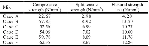
In this present experimental investigation Ordinary Portland Cement of 53 Grade Ultra Tech (Birla Super) is used. To ascertain the physical characteristics of the cement, tests were conducted in accordance with the Indian standards confirming to IS-12269:1987. Fractions of fine aggregates passing through 4.75 mm sieves and entirely retained on 150µ sieve are used. The test on fine aggregate was conducted in accordance with IS: 650-1966 & IS: 2386-1968 to determine specific gravity and fineness modulus. The Fine aggregate satisfied the requirement of grading Zone II as per IS: 383 – 1970 (Reaffirmed 2007). Crushed Granite stone with Two different sizes of coarse aggregates were used, 60 % of coarse aggregate passing 20 mm sieve size and retained on 12.5mm sieve, remaining 40% of coarse aggregate passing 12.5 mm sieve size and retained on 10 mm sieve were used. The tests on coarse aggregate were conducted in accordance with IS 2386-1963 to determine specific gravity and fineness modulus. For mix proportioning of High Performance Concrete, Glenium ACE 30, with Poly carboxylic based ethers as Super Plasticizer as chemical admixture are used supplied by BASF India Ltd. Bangalore. Micro silica a dry powder available in densified form and Ground Granulated Blast Furnace Slag (GGBFS) is a dry powder as supplied by M/s Ultra Tech Aditya Birla Group India Pvt. Ltd, Bangalore are used as mineral admixtures in experimental program. Crimped end steel fibers having aspect ratio of 80, procured from Stewols India (Pvt) ltd, Nagpur-Maharashtra. Ordinary potable water was used for mixing and curing purpose. To determine the mix proportions for M60 grade concrete (HPC), tests on trial mixes were carried out and was finally selected with required workability of 25-50mm slump,binder 8% of silica fume is replaced by weight of cement and 15% of GGBS, 0.8% of superplasticzier, 0.65% steel fbers by volume of concrete having aspect ratio of 80 were used. For 50mm slump value, the concrete mix proportional is obtained after trail mixes viz: Cement: Silica fume: GGBS: FA: CA: Water (1: 0.1: 0.19:0.99:2.55:0.38) and same is adopted for present experimental investigations. The hardened properties of concrete matrix used for Case A to Case F as shown in Table No.1.
Prepation of test specimens
layers having steel reinforcements of 3 # 12 mm dia at bottom and 2 # 10mm dia at top with two legs vetical shear of 8mm dia at 75mm c/c with HYSD bars (Figure No.1) conforming to IS: 1786 (grade Fe 500D), further the test beam specimens are divided into six categories (Case A to Case F) according to their material combination as listed below (Srinivas and Dr.Sadath Ali Khan Zai, 2017).
Case A(Full M20 grade concrete beam test specimen).
Case B(Full M60 grade concrete beam test specimen).
Case C (Two layered M60/M20 grade concrete beam,
M60 depth is 50mm from top).
Case D(Two layered M60/M20 grade concrete beam,
M60 depth is 70mm from top).
Case E(layered M60/M20/M60 grade concrete beam, M60
depth is 50mm in upper layer, M20 depth
is 90mm in middle layer and M60 depth is 90mmin
bottom layer).
Case F(layered M60/M20/M60 grade concrete beam, M60
depth is 70mm in upper layer, M20 depth is 80mm in
[image:3.595.304.558.141.800.2]middle layer and M60 depth is 80mmin bottom layer).
Table 1. Properties of Hardened Concrete (Srinivas and Dr.Sadath Ali Khan Zai, 2017)
Mix Compressive strength (N/mm2)
Split tensile strength (N/mm2)
Flexural strength test (N/mm2)
C a se A 2 2 . 67 2 . 9 8 4 . 2 0
C a se B 6 7 . 85 8 . 9 2 1 3 . 27
C a se C 52.56 6.99 10.27
C a se D 54.06 7.02 10.60
C a se E 5 9 . 78 8.09 11.76
C a se F 62.55 8.67 12.86
Test programme
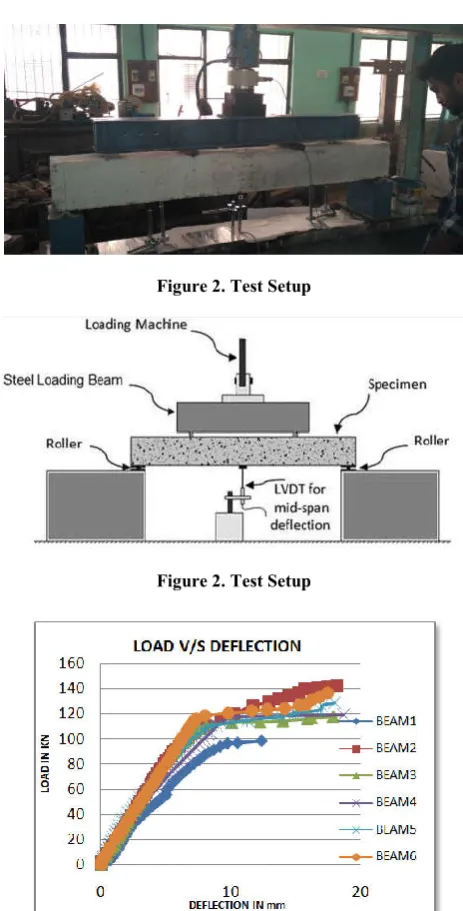
The experimental programme consists of testing six series of test beam specimen under flexural loading, the loading arrangements and instrumentation are shown in figure No.2 simply supported reinforced concrete beam under two point loading at the one third of span is considered. The parameters under study are Energy absorption capacity, Toughness index, Ductility Factor, Cracking Moment. Test Beam specimens are designated as Beam1/CaseA, Beam2/CaseB, Beam3/CaseC, Beam4/CaseD, Beam5/CaseE, Beam6/CaseF, respectively and same is shown as in table no.2
Figure 1. Reinforcement details
RESULTS
Flexural behaviour on layered test beams specimens
The behavior of the test beam specimens with constant tension reinforcements are tested under pure bending conditions for Case A to Case F (Beam 1 to Beam 6) and the test results of each test beam specimen with respect to deflection, cracking loads, energy absorption capacity, ductility index and
[image:3.595.34.293.346.427.2]toughness index are presented in respective tables and bar charts. The experimental cracking moment, cracking loads are compared with corresponding moments and loads calculated as per IS 456:2000.
Table 2. Details description of Concrete Matrix for Case A to Case F
Sl. No.
Mix Description Cross Section of Test Beam Specimen
1
Case A
Beam with M20 grade concrete (Control specimen).
2
Case B
Beam with M60 grade concrete.
3
Case C
The beam with tension layer made of normal M20 grade concrete while the compression layer of 0.2857d made with highstrength concrete beam.
4
Case D
The beam with tension layer made of normal M20 grade concrete while the compression layer of 0.40d made with high strength concrete beam
5
Case E
The beam with compression layer made of normal M20 grade concrete while the tension layer of 0.2857d made with high strength M60 grade concrete.
6
Case F
[image:3.595.41.283.597.653.2]Figure 2. Test Setup
Figure 2. Test Setup
[image:4.595.39.288.573.773.2]Figure 3. Combined Load-Deflection Curves for beam 1 to beam 6
Table 3. Experimental and Theoretical Values of First Crack Loads
Mix
Test B ea m sp ec i men
Experimental. first crack load in KN (E)
Theoretical. first crack load in KN (T)
Ratio T/E.
CASE A B1 11.77 11.84 1.00
CASE B B2 32.24 20.51 0.65
CASE C B3 17.65 20.51 1.16
CASE D B4 19.62 20.51 1.04
CASE E B5 28.44 20.51 0.72
CASE F B6 30.39 20.51 0.70
Figure 4. Comparison of Experimental and Theoretical First crack load
Table 4. Theoretical and experimental ultimate loads for all beams
Mix Test B ea m sp ec i men
Expt. Ultimate load in KN (E)
Theoritical. Ultimate load
in KN (T)
Ratio T/E.
CASE A B1 98.51 62.62 0.63
CASE B B2 142.54 187.92 1.31
CASE C B3 117.98 187.92 1.59
CASE D B4 119.12 187.92 1.57
CASE E B5 128.25 187.92 1.46
CASE F B6 134.25 187.92 1.39
Figure 5. Comparison of Experimental and Theoretical Ultimate load
Load-deflection behaviour under static loading
Deflection is one of the important serviceability limit state to be satisfied in the design of concrete structures. . Deflection of a beam primarily depends upon the type of loading, span, and moment of inertia of the section and modulus of elasticity of concrete. A significant overall property of a structural member is its response to load which is completely described by load deflection relationship and same is shown in Figure 3. It is observed that for all test beam specimens the curves shows linear variation up to first crack level and behave in a nonlinear way with further increase in load. The load deflection response can be idealized into three phases. In the first phase the load deflection plot is nearly straight for an uncracked section and the behavior is elastic. Phase two with a curved portion corresponds to deflection after the concrete in tension has cracked. At this stage the tensile steel will still be elastic. After the third phase either the steel or the concrete in compression or both become plastic and the strain increases rapidly up to failure.
First crack load
This is the load at which the first visible crack appears on the surface of the beam due to the development of tensile stresses. The experimental and theoretical loads at the first visible crack for all the six test beams specimens are shown in Figure 4 and Table 3.
Ultimate load
Energy absorption capacity
[image:5.595.46.282.155.386.2]The Energy absorption capacity of given material can be obtained from the load versus deflection curve of the specimen. The value of Energy absorption capacity was computed from the area under the load deflection curve.
Table 5. Energy absorption capacity of different concrete beams
M i x Test Beam
specimen
Energy absorption capacity (kN-mm)
C ASE A B1 105.50
C ASE B B2 284.42
C ASE C B3 161.53
C ASE D B4 191.39
C ASE E B5 235.92
C ASE F B6 250.45
Figure 6. Energy Absorption capacity for all Beams
Toughness index
Toughness Index is defined as the ratio of area under the curve up to ultimate load to area under the curve up to first crack load. The value of toughness index for different beam specimen under investigation is given in table below.
Toughness index = Area under the curve upto ultimate load
[image:5.595.316.550.203.425.2]Area under the curve upto irst crack load
Table 6. Toughness index of different concrete beams
Test Beam specimens Toughness Index
B1 10.25
B2 25.50
B3 14.39
B4 16.25
B5 19.25
B6 21.65
Figure 7. Toughness Index for all Beams
Flexural ductility index
Ductility is the measure of the element capacity to undergo inelastic behavior and absorb energy. Displacement ductility, μd, is defined as the ratio of deflection at ultimate moment to
the deflection at first yield. In general, high ductility ratios indicate that a structural member is capable of undergoing large deflection prior to failure. Displacement ductility is given by
µd =δu /δy
Table 7. Ductility Index
M i x δy, mm δu, mm µd = δu / δy
C ASE A 9 . 1 76 1 2 . 36 8 1 . 3 47 C ASE B 7 . 5 81 1 8 . 25 0 2 . 4 07 C ASE C 9 . 5 92 1 7 . 94 2 1 . 8 79 C ASE D 9 . 2 80 1 8 . 72 2 . 0 17 C ASE E 8 . 5 12 1 8 . 02 4 2 . 1 14 C ASE F 7 . 8 3 1 7 . 50 2 . 2 33
[image:5.595.305.561.469.703.2]Figure 8. Ductility Index for all Beams
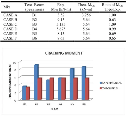
Table 8. Theoretical and Experimental Cracking Moment
Mix Test B ea m sp ec i men s
Exp. MCR (kN-m)
Theo. MCR
(kN-m)
Ratio of MCR
Theo/Exp.
CASE A B1 3.52 3.256 1.00
CASE B B2 9.15 5.64 0.63
CASE C B3 5.135 5.64 1.09
CASE D B4 5.675 5.64 0.99
CASE E B5 8.13 5.64 0.69
CASE F B6 8.63 5.64 0.65
Figure 9. Cracking Moment for all Beams
Cracking moment
The Table 8 shows the observed moments at first crack, Mcr(exp), is based on the first visible crack in the pure bending
region. The predicted cracking moments, Mcr(Theo), were
[image:5.595.44.285.547.774.2]= ∗ − ; = 0.7 ′
Where: Ig: gross moment of inertia, yt: distance between NA
and extreme tension fiber
The obtained ratio of the Mcr(exp) to the corresponding Mcr(Theo
is tabulated in Table 8
Conclusion
Load and Deflection behavior
Load deflection curve of all the test beams specimens shows linear variation up to first crack level and behave in non-linear way with further increase in load.
The first crack load are 11.77 KN, 32.24 KN, 17.65 KN, 19.62 KN, 28.44 KN, 30.39 KN for Case A, B, C, D, E and F respectively. Case F shows the highest first crack load among all the layered test beam specimens
The ultimate load are 98.51 KN, 142.53 KN,117.97 KN, 119.02KN, 128.25 KN and 134.25 KN for Case A, B, C, D, E and F respectively. Case F shows the highest ultimate load among all the layered test beam specimens
Energy Absorption Capacity
All layered test beam specimens shows increase in energy absorption capacity w.r.to M20 (Case A) by 53.10%, 81.40%, 123.60% and 137.40% for Case C, Case D, Case E and Case F respectively.
Toughness Index
All layered test beam specimens shows increase in toughness index w.r.to M20 (Case A) by 40.40%, 58.54%, 87.80% and 111% for Case C, Case D, Case E and Case F respectively.
Ductility Index
All layered test beam specimens shows increase in ductility index w.r.to M20 (Case A) by 39.15%, 49.70%, 57% and 65.80% for Case C, Case D, Case E and Case F respectively.
Cracking Moment
The cracking moment of all the layered beams shows increasing order w.r.to M20 (Case A), by 46%, 61.40%, 130.40% and 144.60% for Case C, Case D, Case E and Case F respectively. It can be concluded that Case F (M60/M20/M60,
30% of M60 grade of concrete at upper layer/portion, 35% of
M20 grade of concrete at middle layer/portion and 35% of M60
grade of concrete at bottom layer/portion) shows better energy absorption capacity, toughness index, ductility index and cracking moment as compared to the other Cases.
REFERENCES
Dr. H. Eramma, Madhukaran and B S Karthik, 2014. "Behavior of Concrete Grade Variation in Tension and Compression Zones of Rcc Beams", International Journal
of Advanced Technology in Engineering and Science,
ISSN: 2348 – 7550 Vol No.2.
Holschemacher, K., Iskhakov, I., Ribakov, Y. and Mueller, T. 2012. “Laboratory Tests of Two-Layer Beams Consisting of Normal and Fibered High Strength Concrete: Ductility and Technological Aspects”, Mechanics of Advanced
Materials and Structures, Vol. 19, Issue 7.
Iskhakov and Y. Ribakov, 2007. “A design method for two-layer beams consisting of normal and fibered high strength concrete, Materials & Design”, Volume 28, Issue 5, 2007, Pages 1672-1677, ISSN 0261-3069.
Iskhakov and Y. Ribakov, 2013. “Two-layer concrete bridge beams as composite elements”, Structural Concrete, SEP, Volume: 14 Issue: 3 Pages: 271-277.
Iskhakov, I., Y. Ribakov and Holschemacher, K. and Mueller, T. 2014. “Experimental Investigation of Full Scale Two-Layer Reinforced Concrete Beams”, Mechanics of
Advanced Materials and Structures, Vol. 21, Iss. 4.
Kandekar, S. B., P. D. Dhake, M. R. Wakchaure, 2013. "Concrete Grade Variation In Tension and Compression Zones of Rcc Beams", International Journal of Innovative
Research in Science, Engineering and Technology, ISSN:
2319-8753 Vol 2.
Lalit Rathee and Naveen Hooda, 2016. “A study on Ultra High Performance Concrete using Mineral admixture and steel fibres”, International Journal of All Research Education
and Scientific Methods, ISSN: 2455-621, Vol 4, Issue 7.
Somasekharaih, H.M., Mahesh Sajjan, Nelson Mandela, 2015. “A study on fiber reinforced high performance concrete using multiple mineral admixtures”, International Journal
of Research in Engineering and Technology, ISSN:
2319-1163, Vol 4, Issue 10.
Srinivas, H.R and Dr.Sadath Ali Khan Zai, 2017. “Experimental investigation of layered concrete matrix consisting of normal and fibre reinforced high performance concrete”, International Journal of Current Research, Vol. 9, Issue, 10, pp.58597-58600,
Venkatesan, V.R., P.N.Raghunath and K.Sugana, 2015. “Flexural behavior of high strength steel fibre reinforced concrete beams”, International Journal of Engineering Science and Innovative Technology