FISH ROBOT POSITION CONTROL USING THE OBJECT TRACKING ALGORITHM
*Prof. Dr. Kyoo Jae Shin and YogendraRao
Department of ICT Creative Design, Busan University of Foreign Studies, BUFS,
ARTICLE INFO ABSTRACT
In the attention has developed
that mimic the structure and function of biological systems and snake etc. T
robot in the aquarium because we need to has modeled
recognize the
device that is camera. Here, we motion of the fish robots position data;
we send this data to control and track Certainly, the
experimental system.
Copyright ©2016, Prof. Dr. Kyoo Jae Shin and YogendraRao
License, which permits unrestricted use, distribution and reproduction in any medium, provided the original work is properly cited.
INTRODUCTION
“A lot of conventional thinking pervades the field says Morley Stone, a program manager in Advanced Research Projects Agency’s defense
(www.darpa.mil). In the last two decades, the research on biomimetic fish robots has fascinated scientific
attention progressively (Polverino et al., character of high flexibility and intelligence,
robot has developed in the field of underwater robots
Liu et al., 2014). Predominately, Biomimetic robot systems are robots that mimic the structure and function of biological systems such as natural tuna, cheetah, ant, kangaroo and snake et al. The robotic dynamics is the new sub
inspired design. It is about learning concepts from nature and applying them to the design of real world engineered systems. Oftenly, biological systems have inspired
(KyooJae et al., 2010). “People have been trying to copy nature for a very long time,” says Jerry Pratt, a research scientist at the Institute for Human and Machine
(www.ihmc.us).We have designed the fish robot
underwater robots. The performance of the developed biomimetic robot is excellent because it imitates the natural
*Corresponding author: Prof. Dr. Kyoo Jae Shin,
Department of ICT Creative Design, Busan University of Foreign Studies, BUFS, Busan, Republic of Korea.
ISSN: 0975-833X
Article History:
Received 22nd August, 2016
Received in revised form 19th September, 2016
Accepted 28th October, 2016
Published online 30th November,2016
Citation: Prof. Dr. Kyoo Jae Shin and YogendraRao
Journal of Current Research, 8, (11), 41012-41020.
Key words:
Fish robot,
Biomimetic robot system, Image processing, RF modem, Moving object, Object tracking algorithm.
RESEARCH ARTICLE
FISH ROBOT POSITION CONTROL USING THE OBJECT TRACKING ALGORITHM
Prof. Dr. Kyoo Jae Shin and YogendraRao Musunuri
Department of ICT Creative Design, Busan University of Foreign Studies, BUFS, Busan
ABSTRACT
In the last two decades, the research on biomimetic fish robots has
attention progressively. With its character of high flexibility and intelligence, biomimetic fish robot developed in the field of underwater robots. Predominately, Biomimetic robot systems
that mimic the structure and function of biological systems such as natural fish, and snake etc. This paper addresses the detecting the moving objects
in the aquarium because we need to acquire the position to
has modeled to detect the position of the fish robot using the MATLAB and Simulink. This intends to recognize the neighborhood of the fish robots using an image processing technique through video device that is camera. Here, we have applied the proposed object tracking algorithm to control the
tion of the fish robots. This algorithm used to detect the moving objects,
position data; we compute the distance between two fish robots using mathematical expression. send this data to control and track the fish robots through
Certainly, the performance test of object tracking algorithm has been satisfied experimental system.
Prof. Dr. Kyoo Jae Shin and YogendraRao Musunuri. This is an open access article distributed under the Creative Commons Att and reproduction in any medium, provided the original work is properly cited.
“A lot of conventional thinking pervades the field of robotics,” in the US Defense Agency’s defense sciences office In the last two decades, the research on biomimetic fish robots has fascinated scientific communities’ 2012). With its character of high flexibility and intelligence, biomimetic fish underwater robots (Hongli Predominately, Biomimetic robot systems are he structure and function of biological systems such as natural tuna, cheetah, ant, kangaroo and snake sub-category of bio-inspired design. It is about learning concepts from nature and
real world engineered systems. inspired to make robots “People have been trying to copy long time,” says Jerry Pratt, a research the Institute for Human and Machine Cognition designed the fish robot in the field of . The performance of the developed biomimetic robot is excellent because it imitates the natural
Creative Design, Busan University of Foreign Studies,
Fish such as Korean DOMI (Kyoo
explored manuscripts that detecting object algorithms such as; the design of aquarium robot world using
position method (KyooJae
aquarium fish robot system with drawing fish of augmented reality (KyooJae et al., 2016) and realization of fish robot tracking control using position detecting algorithm
et al., 2016). In the previous paper, the designed fish robot has researched to develop an algorithm
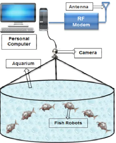
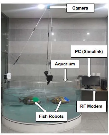
position of the fish robot. In order to realize the aquarium robot world, it needs to track the fish robots. The
fish robot world consists of PC (Personal Computer), Camera fish robot, and RF (Radio Frequency) Modem
Fig.1. The developed fish robot consists of the head, body, 2nd stage body and tail which is connected point driving joints of the fish robot.
maximize the momentum of the
robot is designed through the analysis of the biological swimming (KyooJae et al., 2015)
was applied to the kinematic analysis of swimming algorithm. We have
method of the streamer model that utilizes techniques to mimic the biological fish (KyooJae et al
robot has two operating modes such as manual and autonomous modes. In the manual mode the fish robot swimming is operated by using the RF Transceiver. In the autonomous mode the robot is controlled through the
International Journal of Current Research Vol. 8, Issue, 11, pp.41012-41020, November, 2016
INTERNATIONAL
OF CURRENT RESEARCH
Prof. Dr. Kyoo Jae Shin and YogendraRao Musunuri, 2016. “Fish robot position control using the object tracking algorithm
FISH ROBOT POSITION CONTROL USING THE OBJECT TRACKING ALGORITHM
Musunuri
Busan, Republic of Korea
robots has fascinated scientific communities’ ter of high flexibility and intelligence, biomimetic fish robot Biomimetic robot systems are robots such as natural fish, cheetah, ant, kangaroo detecting the moving objects that is earlier developed fish to track the fish robot. This algorithm the MATLAB and Simulink. This intends to using an image processing technique through video object tracking algorithm to control the detect the moving objects, by using this detecting using mathematical expression. Then, rough RF (Radio Frequency) modem. has been satisfied by the proposed
under the Creative Commons Attribution and reproduction in any medium, provided the original work is properly cited.
KyooJae et al., 2014). We have manuscripts that detecting object algorithms such as; the design of aquarium robot world using detecting fish robot ae et al., 2016), realization of aquarium fish robot system with drawing fish of augmented 2016) and realization of fish robot
tracking control using position detecting algorithm (KyooJae In the previous paper, the designed fish robot has
researched to develop an algorithm to find and track the . In order to realize the aquarium robot world, it needs to track the fish robots. The proposed aquarium consists of PC (Personal Computer), Camera, and RF (Radio Frequency) Modem as shown in the obot consists of the head, 1ststage stage body and tail which is connected through
two-fish robot. The Model is analysis to maximize the momentum of the fish robot and the body of the robot is designed through the analysis of the biological 2015). Also, Light hill dynamics was applied to the kinematic analysis of the robot fish have applied to the approximate method of the streamer model that utilizes techniques to mimic et al., 2015). The swimming fish ting modes such as manual and autonomous modes. In the manual mode the fish robot swimming is operated by using the RF Transceiver. In the autonomous mode the robot is controlled through the
INTERNATIONAL JOURNAL OF CURRENT RESEARCH
microcontroller unit. It consists of two servo motors and three PSD (Position Sensitive Detector) sensors in the fore head of fish robot to detect obstacles; Air bladder device in ahead portion used to moving central weight point and
communication port is used to receive data (KyooJae et al., 2016). We have designed an aquarium robot world using
fish robot. In order to realize the aquarium robot world, it needs the position data so that it has researched about the detecting fish robot using the boundary detecting, color weight and objet tracking algorithms. In this paper, the newly proposed method: object tracking algorithm is applying to the fish robot to detect the position and analyze the motional behavior when we track the fish robot. The object tracking algorithm accumulates fully based on the frames of moving object in the moving picture (KyooJae et al., 2015). In this algorithm, detect the moving object using the optical flow technique because it is one of the good techniques to analyze the motion between two consequence frames. The frame is composed of picture elements just like a chess board (KyooJae et al., 2015). Here, picture elements (has some coordinates, no pixel coordinate would not match on the screen.
So that, this algorithm correlates the two frames and estimate the motion between two frames to find the position of the object
because every object has some particular pixels (KyooJae et al., 2016) when image captured by camera, that would not
[image:2.595.336.530.380.767.2]change continuously, so that, could detect the position of fish robot (KyooJae et al., 2015). It was verified by the performance test for the designed aquarium fish robot world.
Fig.1. The aquarium fish robot world to control the fish robot
Modeling of the fishrobot control
Biomimetic robot systems has developed in the field of underwaterrobotsfor an aquarium.The assembledfish robot consists of the head, 1st stage body, 2nd stage body and tail, which is connected through two point driving joints as shown in the Fig.2(a). Because the robot is need to maximize the momentum and the body of the robot is designed through the analysis of the biological fish swimming. Also, it was applied to the kinematics analysis of fish robot swimming algorithms, which is basically Lighthill dynamics. The center of the fish
robot gravity is transferred to a one axis sliding and it is possible to the submerged and emerged of robot by the weight moving unit (KyooJae et al., 2016). In addition to the configuration ofthe entirefish robot, the control system was designed to apply anartificial intelligencealgorithmand apply the AVR microcontroller in order tomimicthebiologicalcontrol for the robot. The control systemmainly consists of RF modem, three PSD sensors, two Servo motors and weight moving unit.These are connected to the Microprocessor (Micom). The Micom should operate the all connected devices to it and the RF modem is used to control the action of the fish robot in the manual mode like left, right,forward,up and down. Otherside, PSD sensors were used to detect the obstacles like aquarium walls and other objects such as fish robots, and servo motors operated with the sensor feedback signal.The weight balancing unit used to balance the fish robot using the sliding method. In the sliding method, the slider mechanism (Weihs,1972) has used to slide the weight balancing unit. So that, when weight balancing unit come towards the head of the fish robot, then the fish robot goes down, otherwise, the weight balancing unit come towards the tail of the fish robot, it floats on the water as shown in the Fig.2(b), and communication port designed fordata acquisition from the PC. The swimming form of fish robot isa continuous function with discretefunction for thekinematicstreamer model through theanalysis byLighthill (Kim,2012), whichis equal to theequation (1), and it expresses the movement of the biomimeticfish robot.
a)
b)
[image:2.595.70.263.399.638.2]
x,
t
C
x
C
x
sin
kx
2π
f
t
y
i
1
2 2
i M 2π kx sin x C x C 2 2 1 (1)where
y
i
x,
t
is the transverse displacement of the bio-mimetic fish robot along the x-axis at time t, x is the axial displacement of the body (head and tail), C1 and C2 are the linear coefficient and the quadratic coefficient of the bodywave amplitude envelope of fish robot respectively,
2 k is
multiples of the body wave or body wave number and
is the wave length,
is the body wave frequency of the biomimetic fish robot andf
is the propelling frequency.The error is defined in the equation(2) which is the traveling wave approximation using the 3 joints, and the joint angle can be approximated as equation (3) by a sine wave having the same frequency as like as traveling wave.
1 n 0 i end x .tx gx f x
error
(2)
i
i
i
a
sin
2
ft
p
θ
(3)
Then, the frequency of the fish robot can be determined using the light hill analysis to swim in the water. In order to up and down swimming, the robots swim are designed to move back and forth to the center of gravity (Hirata et al., 2000) estimation point by the sliding weight center point method that is like as the gravity principle of bio-mimetic fish robot (Kim, 2012). It is important to control the tracking speed, so that the speed of the motor is highly depends on the value of torque TL. It can improve the speed performance of the motor by using a proportional feedback controller. The controller is composed of a sensor to sense the speed and an amplifier with gain K (proportional control) in the configuration of fish robot. The speed at the motor shaft is sensed by the potentiometer with gain Kt and PID (Proportional-Integral-Derivative) controller can be expressed in the equation (4).
s K s K K s i dp
PID (4)
where Kpis the proportional gain,Kdis the differential gainandKiis the integral gain.The input to the control system is converted from voltage Vinto speed ωin using the potentiometer gain Kt. Hence, assumingLa= 0, we will get equation (5).
R B K K R J
V
ss J R K s ω a a m b a a m (5)
where
ω
s
: The speed of the fish robot ,K
m: motor gain,R
a: armature resistance,J
: moment of motor inertia,B: viscous friction coefficient of the motor shaft,K
b: gain of back emf,a
L
: armature inductance,T
L:external load torque consideredas a disturbance and
V
a
s
: the applied voltage. In order to control link angle, the simulink model to control the link bodyof the fish robot has shown in the Fig.3. In this, first block is the dynamic motion of the fish robot and remaining blocks are the model is used to control the link angle of thefish robot. The link angle output (LAO) has expressed in the equation (6).
m b a m t d
m t p
m t i 2 a 3 m i p i d m 2 K K K K K K s K K K B R K K s J R s K K K sK K K s LAO (6) [image:3.595.309.553.378.473.2]Where Km is the motor gain,Kdis the differential gain,Kiis the integral gain, Kp is the propor- tional gain, J is moment of motor inertia,Kbgain of back emf, Kt is the angle signal gian,Rais the armature resistance, B is the viscous friction co- efficient of the motor shaft,Lais the armature inductance, TL is the external load torque considered as a disturbance and Va
s is the applied voltage.The link angle command has produced from the equation (1)~(3). The error is computed that subtract the angle command to feedback signal of the link angle that is defined by the integral processing of the link potetiometer output signal. The error is compensated by PID controller and converted it into the driving signal of dc motor. The external disturbance torque TLis compensated by feedback of the motor speed and it is realize the control of link angle of the fish robot.The control of the fish robot canbe monitored through the live video which is connected to the live video device that is camera.Fig. 3. The link angle control of the fish robot
Fig . 4. The position detecting of fish robot using the optical flow
Design of detecting objects using an optical flow
[image:3.595.312.548.515.692.2]Fig. 5. The position concept design of the fish robot
Fig. 6. The proposed object tracking position control system
Fig. 7. The realization of fish robot using object tracking algorithm
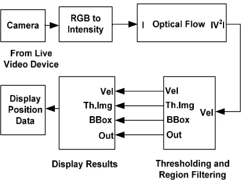
The model of the detecting an object consists of live device block which is camera, rgb to gray, optical flow, thresholding and filtering, and display results. In this, the main concerns about an Optical flow. The aim of an optical flow is to estimate the motion filed from time-varying image intensity. The Optical Flow (KyooJae et al., 2015) is used to analyses the motion of the moving objects and it estimates the direction and speed of object motion from one image to another image and from one video frame to another. The Simulink model as shown in the Fig.4 and it consists of several major blocks such as:
(1) Live video device: This is the video device which is connected to the Simulink library from the image acquisition tool box. To set the camera, double click on this block → select the camera → select apply button →select ok (KyooJae et al., 2015).
The output of this block is image and given as input to the second block that is RGB to Gray.
(2) RGB to Gray: This block takes the color data and converts into the gray color by using the color codes which starts from 000 to 255.
(3) Optical flow: This optical flow is the pattern of apparent motion of objects,surfaces, and edges in a visual scene caused by the relative motion between an observer and the scene. In this, the velocity of each frame will be estimated by using Optical flow method (KyooJae et al., 2016).
(4) Thresholding and Filtering: This block thresholds the image and filters the image from original image. This model locates the fishes in each binary image using the Blob Analysis block. Then, it uses the Draw Shapes block to draw a green rectangle around the fish robots.
(5) Display Results: The Results window shows the position of number of fishes around green rectangle in the region of aquarium.
(6) Display Position Data: This window shows the position data of the detected fish robot in the aquarium.
The proposed position detecting of fish robotusing object tracking algorithm
[image:4.595.71.253.551.777.2]Fig. 8. Experimental result of 2 axes Position detection of fish robots. (a) Video file, (b) RGB to Gray, (c) Threshold image, (d) Optical flow, (e) Object tracking algorithm, (f) Display results
Fig. 9. Experimental result of 2 axes Position detection for fish robots. (a) Video file, (b) RGB to Gray, (c) Threshold image, (d) Optical flow, (e) Object tracking algorithm, (f) Display results
[image:5.595.168.426.568.756.2]In the Fig.5 representing two images are different frames and they will have allocated different coordinates when compare (n-1) frame and (n) frame, the position will be changed, but pixel coordinates of the object will remain same so that the position of the object will be detected (William K Pratt et al., 1978). So that assume the intensity of two images is same, this is expressed mathematically in the equation (6).
x u,y v
I
x,y
I2 1 (6)
The above equation can be expressed with time is shownin the equation (7)(Kyoojae et al.,2016).
x u, y v,t 1
I
x,y,t
I2 1 (7)
The equation (7) becomes, after applying Taylor series left hand side that is
x,y,t
I
x,y,t
I dt dI v dy dI u dx dI (8)
After solving the equation (8), we get the equation (9) (KyooJae et al., 2016).
dt dI v dy dI u dx dI (9)
where It
dt dI y, I dy dI , x I dx dI
the equation (9) becomes the
equation (10).
t y
xu I v I
I
(10)
The equation (10) is called as standard equation ofan optical flow. This is used to detect the motion of the frames in video and can get the motion vectors on the object as shown in the experimental results in theFig.8 (KyooJaeet al., 2016). To calculate the optical flow between two images, you must solve the following optical flow limitation equation is shown in the equation (11).
0
y t
xu I v I
I (11)
where
I
x,IyandI
t are the spatiotemporal image brightness derivatives, where u is the optical flow in the horizontal (x) direction and v is the optical flow in the vertical (y)direction. By assuming that the optical flow is smooth over the entire image, this method computes an approximate direction of the velocity field
u,v
T that minimizes the following equation is (KyooJae et al., 2015).
dxdy y v x v y u x u α dxdy I v I u I E 2 2 2 2 2 t y x
(12)In this equation x u
and
y u
are the spatial derivatives of the
optical velocity component u, v and
scales the globalsmoothness term. This method minimizes the equation (12) to obtain the velocity field,
u,v
for each pixel in the image. This method is given in the following equations (13) and (14) (KyooJae et al., 2015).
2 y x 2 2 t y x, k y y x, k x x y x, k y x, 1 k I I α I v I u I I u u (13)
2 y x 2 2 t y x, k y y x, k x y y x, k y x, 1 kI
I
α
I
v
I
u
I
I
v
v
(14)In these equations
y x, k y x, k ,v
u is the velocity estimate for the
pixel at
x
,
y
andukx,y,vkx,y is the neighborhood average of y x, k y x, k v ,
u when k = 0, the initial velocity is 0.Calculate u and
v by following steps.
(1).Compute
I
x andIy using the Sobel (KyooJae et al., 2015) convolution kernel, [−1 −2 −1; 0 0 0; 12 1], and its transposed form, for each pixel in the first image.(2).Compute
I
tbetween images 1 and 2 using the[−11] kernel. (3).Assume the previous velocity to be 0, and calculate theaverage velocity for each pixel using [010; 10 1; 010],as a convolution kernel.
(4). Iteratively solve for u and v.
In order to solve the optical flow constraint equation for u and v, the proposed method divides the original image into smaller video frames and assumes a constant velocity in each frame to compare two frames to detect the position. Then, the two axes can be displayed on the two axes data display on the PC in the display block. These experimental results are as shown in the Fig.9.The proposed object tracking position control system consists of control the link body of the fish robot and optical flow detecting algorithm as shown in the Fig.6.After detecting the moving object, we get the position data. By using the position data, we use the RF Modem to communicate the fish robot data between PC and fish robot. By using the angle commands, the fish robot can turn left, right, forward, up, and down. This motion can be achieved with moving the link body of the fish robot. By using this link control, we can perform the tracking control of the fish robots. This optical flow algorithm is applying to the fish robot to detect the position to analyze the motional behavior of the fish robot and it works fully based on the frames (images) of moving object. So that, this algorithm compares the two frames and estimate the motion between two frames to find the position of the object because every object has some particular pixels when image captured by camera, that would not change continuously, so that, could detect the position of fish robot. It was verified by the performance test for the designed aquarium fish robot world.
RESULTS AND DISCUSSION
motion of fish robots was captured by using the camera, and then it sent to the PC.To acquire the data, use the live videodevice block from the Simulink data acquisition tool box and the Simulink Model as shown in the Fig.4. Then, we acquired the video data and analyzed by using the object tracking algorithm.The experiment of this algorithm held in two camera views. They are front view camera and top view camera respectively. The experimental results of the top view camera areas shown in the Fig.8. Let us consider three fish robots f1, f2, andf3. Let f1 be the orange fish robot, f2 be the blue fish robot and f3 be the gold fish robot and its coordinates are (x1, y1), (x2, y2)and (x3, y3) respectively, as shown in the results. The Fig. 8 (a) shows the original video captured by the camera and it covers the entire aquarium robot worldto detect the swimming motion of the fish robot. The Fig.8(b) shows converting frame from RGB to gray to distinguish the object from the background. The Fig.8(c) shows the result of the threshold or filtered the image used to detect the object in the frame. The Fig.8(d) shows the motion vectors are surrounded by the fish robot which gives the position of the fish robot.The Fig.8(e) shows the thick rectangle is surrounded by the fish robot that indicatesdetectingthe fish robot in theaquariumand theFig.8(f) shows the fish robot coordinates after detecting the moving objectare (x1, y1: 719,527), (x2, y2: 528,477)and (x3, y3: 375,323).In this analysis, the performance of experiment result is satisfactory by using the object tracking algorithm.The experimental results of the optical flow algorithm using the front view camera as shown in the Fig.9. Let f4 be the orange fish robot, and f5 be the gold fish robot and its coordinates are (x1, y1) and (x2, y2) respectively, as shown in the results. The Fig.9(a) shows the original video captured by the camera and it covers the front view of the aquarium robot worldto detect the swimming motion of the fish robot.The Fig.9(b) shows converting frame from RGB to grayto distinguish the object from the back ground. The Fig.9(c) shows the result of the filtered object using the threshold value in the frame. The Fig. 9(d) shows the motion vectors are surrounded by the fish robot which gives the position of the fish robot. The Fig.9(e) shows the thick rectangle is surrounded by the fish robot that indicatesdetectingthe fish robot in theaquarium and theFig.9(f) shows the fish robot coordinates after detecting the moving objectare (x1, y1: 719,528), (x2, y2: 689,564). By using this position data,we send the control data to control and track the fish robots using RF (Radio Frequency) modem. The RF modem able to send the data as well as receive the data because it has both transmitter (TX) and receiver (RX) modules included in the single unit with low carrier frequency, from/to the PC. When we compare the performance of the two views of the camera, the top view camera detecting the waves of the water, it makes some noise while detecting the object. And come to other side, in the front view also, the water disturbance makes noise while detecting object, but front view gives some better results than top view camera because of low wave disturbance. The Fig.10 depicts the tracking of two fish robots in x between the two fish robots, in which, red color tracking line represents the red fish robot and blue color tracking line represents the blue color fish robot.When we compare the motion between two fish robots in x direction as shown in the Fig.10.In this graph, on x-axis has taken as values and y- axis has taken as fish x coordinates. It describes the, two fish robots are started at same point and ended at same point. After some distance, at the point (20,300), two fish robots are sagregating each other, from this point, blue fish robot follow the red fish robot and boundwith two fish robots parallel to swim each other.
[image:7.595.307.560.261.648.2]Fig. 11. The tracking of two fish robots in the y direction
Fig. 12. The lead-lag distance tracking between the two fish robots
Fig. 13. The trajectory motion of the two fish robots
with two fish robots parallel to swim each other. The Fig.12 depicts the distance between the two fish robots such as red fish robot and blue fish robot. Let us consider the position of the blue fish robotis (x1,y1), and the position of the red fish
robot is (x2,y2). It will perform the lead-lag action that is red
fish robot is lead from the blue fish robot. The distance between the two fish robots will be computed by using the mathematical expression as shown in the equation (15).
21 2 2 1
2
x
y
y
x
d
(15)
Whered is the distance between two fish robots, x1 and x2 are
the xcoordinates of the blue fish robot and red fish robot, y1
and y2 are the ycoordinates of the blueand red fish robots.It is
realize to test for lead-lag motion control as shown in Fig.12. In this graph, on x-axis has taken as values and y-axis has taken as lead-lag distance. If the distance in equation (15) is satisfied the condition ofd<150mm, two fish robots is swimming continue such as lead-lag motion. If the distance between two fish robots is d>150mm, then lead fish robot will wait for the lag fish robot until lag fish robot reach the lead fish robot. Also if the condition of d<150 mm is satisfied, and the lead fish robot is swimming again. This cycle canters continuously. The Fig.13 shows the trajectory motion of the two fish robots.In this graph, on x-axis has taken as fish x co-ordinates and y-axis has taken as fish y coco-ordinates. The red color trajectory line represents the trajectory path of the red fish robot and blue color trajectory line represents the trajectory path of the blue fish robot. The performance test of the object tracking algorithm has been satisfied.
Conclusion
In this paper, the designed fish robot is used to mimic the biological swimming fish because the performance of the fish robot is excellent. To find the position, we have to detect the moving object which has used the fish robot in the aquarium robot world. In this, we have proposed method, which is optical flow to detect the position of the moving object that is fish robot. The designed fish robot is used the Simulink Model to display the coordinates of the fish robot to analyze the position of the fish robot as it has shown above. By using this position data, we have used the object tracking algorithm as shown in the Fig.6 and corresponding equations implemented in this algorithm from (6) to (14)and send the control data to control and track the fish robots using RF (Radio Frequency) modem. By using this algorithm, we have realized the lead-lag action of the fish robots using the equation (15). This method is modeled in the Simulink for tracking and detecting the fish robot. The experimental results as shown in the above figures from the Fig.(8) to Fig.(13). Finally, we compare the performance of object tracking algorithm, it is confirmed that excellent performance in the field test such as filtering image, enhancing, object detecting, motion vectors and localize the boundary and finally achieved the tracking control of the fish robot through lead-lag action. We realize the lead-lag error minimum is 56 mm and maximum is the 196mm, as shown in the Fig.12, so that, the condition of lead-lag action (56<d<196 mm) has satisfied. Certainly, the performance tests of this algorithm have been satisfied by the proposed experimental system.
Acknowledgement
This work was supported by the KOREA Ministry of Science, ICT and Future Planning. We conduct the Science and Culture
convergence project: Meeting of Robot and Child Picture in the New Sea World Using 3D Hologram. It has supported the research fund. Also, this work granted for Busan University of Foreign Studies.
REFERENCES
Barron, J.L., D.J. Fleet., S.S, Beauchemin and T.A, Burkitt, 1992. Performance of optical flow techniques. CVPR. Christopher M. Bishop, 2009. Pattern Recognition and
Machine Learning. Springer edition, pp.291-320.
Hirata, K., Takimoto, T., and Tamura, K. 2000. Study on turning performance of a fish robot. Pro. 1stInt, Symp, aqua Bio-Mechatronics, pp.287-292.
Hongli Liu., Yufeng Tang., Qixin Zhu and Guangming Xie. 2014. Present research situations and future prospects on biomimetic robot fish. IJSSIS, vol.7, No.2, pp.458-480. Kim, H.J. 2012. Design of autonomous robotic fish swimming
Artificial Intelligence. Master’s thesis, KAIST.
Kim., Y. J., S. J, Kim., K. S, Yang., J. M, Lee., C. H, Yim and D. H, Kim. 2012. Design and Control of a Bio-mimetic Fish Robot. The Korea Society of Mechanical Engineers, Vol.36, No.1, pp.1-7.
Kyoo Jae, S. 2015. Development of Autonomous Bio-mimetic Ornamental Aquarium fish robotic. KIPS transactions on software and data engineering, Vol.4, no.5, pp.219-224. Kyoo Jae, S. and Leenendra Chowdary, G. 2016.Realization of
fish robot Position Recognition Object Using the Color Segment.Proceedings of KIIT Summer Conference, pp.141-144.
Kyoo Jae, S. and YogendraRao, M. 2016.Design of Aquarium Robot World Using Detecting fish robot Position Method. The ICEIC, Danang, Vietnam, pp. 81-84.
Kyoo Jae, S., Amarnathvarma, A., and Ju Hyun, Lee, 2015. Study of detecting the fish robot position using the Average color weight Algorithm.2015 fall conference of the KIPS, pp.481-484.
Kyoo Jae, S., Amarnathvarma, A., andMin Jeong, Kang. 2015. Study of detecting the fish robot position using the object boundary Algorithm. 2015 fall conference of the KIPS, pp.465-468.
Kyoo Jae, S., and YogendraRao, M. 2016.Realization of aquarium fish robot system with drawing fish of augmented reality.FCV 2016, Taka Yama Gifu, Japan, pp.238-243. Kyoo Jae, S., and YogendraRao, M. 2016.Realization of Fish
Robot Tracking Control Using Position Detecting Algorithm. ITC-CSCC, Okinawa, Japan, pp.551-554. Kyoo Jae, S., J. B., Lee and Y. J., Seo, 2014.Design of
Autonomous Bio-mimetic Robotic Fish with Swimming Artificial Intelligence. The 2014 Fall Conf. of the KIPS, pp.913-916.
Kyoo Jae, S., Y.J, Seo and J.W., Jung, 2010.Fish robot, patent no.KR10-1003834.
Kyoo Jae, S., YogendraRao, M. and LenendraChowdary, G.2016.Realization of Fish Robot Position Using Optical Flow Algorithm.Proceedings of KIIT Summer Conference, pp.121-124.
Kyoo Jae, S., YogendraRao, M., and Muhammad Akbar.2016.Realization of aquarium fish robot system with drawing fish of augmented reality.Proceedings of KIIT Summer Conference, pp.121-124.
Comparing Image Data Algorithm. 2015 fall conference of the KIPS, pp.451-454.
KyooJae, S., YogendraRao, M., and YeolJeon, U. 2015.Realization of the Comparing Image Data Algorithm for Fish Robot Position Recognition. 2015 fall conference of the KIPS, pp.431-434.
Kyoo Jae. S. 2016. Realization of Fish Robot Tracking Control Using Optical Flow Object Detecting Algorithm. SPC Journal, South korea.
Maria Petrou and Costas Petrou. 2010. Image Processing - The fundamentals. Wily publication, 2nd edition, pp.591-625. Maria Petrou., PanagiotaBosdogianni, 2005. Image Processing:
The Fundamentals1st edition. Wiley, England, pp.125-138. Maria Petrou., PanagiotaBosdogianni, 2005. Image Processing:
The Fundamentals 1st edition. Wiley, England, pp.308-309. Milan Sonaka., Vaclav Hlavac., and Roger Boyle.2015. Image
Processing, Analysis, and Machine Vision.4th edition, CENGAGE Learning, International edition, pp.116-160.
Polverino, G., Abaid, N., Kopman, V., Macri., S and Porfiri., M. 2012. Zebra fish response to robotic fish: preference experiments on isolated individuals and small shoals. Rafel C. Gonzalez., and Richard E.Woods.2010.Digital Image
Processing, 3rdedition, Pearson, pp.715-804.
Spacek, L.A.1986. Edge detection and motion detection.Image and Vision Computing, vol 4, pp. 43-53.
Steven C, Chapra, 2012. Applied numerical Methods with MATLAB for Engineers and Scientists. McGraw- Hill international edition, 3rd edition, pp.497-531.
Tamal Bose. 2004. Image Processing Fundamentals. John wiley& sons, USA, pp.570-581.
Weihs, D. 1972. A Hydro dynamical analysis of fish turning manoeuvres. Biological Sciences, pp.52-72.
William J, Palm III.2012.Introduction to MATLAB for Engineers. McGraw-Hill international edition, 3rd edition, pp.263-293.
William K, Pratt 1978. Digital Image processing. John Wiley and Sons, England.