Journal of Environmental Protection, 2017, 8, 714-732
http://www.scirp.org/journal/jep ISSN Online: 2152-2219
ISSN Print: 2152-2197
Subsurface Gasoline “Blending” and Forensic
Implications
Jun Lu
1,21AECOM, Long Beach, CA, USA
2China Aerospace Kaitian Environmental Technology Co. Ltd., Changsha, China
Abstract
At petroleum refining facilities with a long operational history, it is likely that some products were released to the subsurface and migrated to the water ta-ble. At or near the water table, these products might have commingled with a pre-existing light non-aqueous phase liquid (LNAPL) plume(s). Depending on the types of products involved and site hydrodynamics, commingling might result in the formation of a “new” LNAPL that exhibits similar charac-teristics to products that were manufactured via intentional blending by refi-nery operations. This study presents a case in which subsurface commingling of two intermediate gasoline-range products occurred at a petroleum refinery. The commingled “new” product appears almost identical to finished gasoline. As the intermediate stream products are typically sourced from refinery and finished products from either refinery or other sources (e.g., pipeline corri-dors), distinction of the commingled gasoline intermediate stream product from finished gasoline becomes critical not only for resolving liability issues, but also development of a remedial strategy. In this study, the source rela-tionship between the gasoline-range intermediate stream product and finished gasoline was resolved using multiple lines of evidence including a gasoline ad-ditive, LNAPL chromatograms, diagnostic compounds (biomarkers) and ra-tios, and site LNAPL hydrodynamics.
Keywords
Petroleum Refining, Gasoline Intermediate Stream Products, Gasoline Blending, LNAPL Comingling, LNAPL Source Identification
1. Introduction
Hundreds of intermediate stream products are generated from relatively limited types of crude oil at major petroleum refineries. This paper opens with an
in-How to cite this paper: Lu, J. (2017) Sub-surface Gasoline “Blending” and Forensic Implications. Journal of Environmental Pro- tection, 8, 714-732.
https://doi.org/10.4236/jep.2017.86046
Received: May 9, 2017 Accepted: June 24, 2017 Published: June 27, 2017
Copyright © 2017 by author and Scientific Research Publishing Inc. This work is licensed under the Creative Commons Attribution International License (CC BY 4.0).
J. Lu
troduction of basic concepts of petroleum refining and gasoline blending pro- cesses, and is followed by descriptions of petroleum releases of petroleum pro- ducts and a discussion of subsequent subsurface commingling. A case study is then presented in which two gasoline intermediate stream products were re-leased, migrated to the water table, and then commingled in right proportions to result in a type of LNAPL that resembled a finished gasoline. As a major pipeline corridor runs by the area and some of the pipelines carried finished gasolines in the past, distinction of the gasoline-range intermediate stream products from fi-nished gasoline was critical to understand the source relationship, which helps not only for liability resolution, but also remedial strategy development.
2. Petroleum Refining and Gasoline Blending Basics
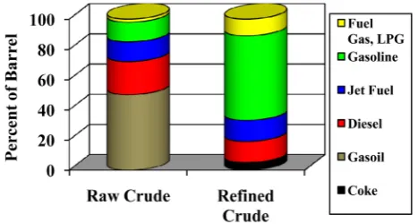
Crude oil is not generally useful. The objective of refining is to turn the crude into useful products such as gasoline, kerosene, diesel, lubricants and feedstock
in petrochemical processes. Figure 1 is a schematic of the change of relative
proportions of each type of product from crude to refined products. As can be observed, in a typical type of raw crude, predominant hydrocarbons are in gasoil
range (i.e., composed predominantly of heavy hydrocarbons), with some diesel,
jet fuel, and gasoline. The refinery converts raw crude into products that are dominantly gasoline that lack gasoil
The refining process starts with crude distillation, followed by a number of processes such as cracking, reforming, isomerization, and alkylation to produce various intermediate stream products. Distillation/fractionation separates crude oil into various “cuts” that are defined by their boiling points. Cracking breaks larger molecules into smaller ones. Reforming converts naphthenes into aro-matics or normal paraffins into branched paraffins. Isomerization converts pa-raffins into isopapa-raffins. Alkylation combines two loweroctane molecules into one higher octane molecule. In simple terms, refining processes separate, re-shape and resize the molecules to convert the entire barrel to high value
prod-ucts [1].
[image:2.595.257.491.567.692.2]Blending is the process that combines intermediate stream products and addi-tives in various proportions resulting infinished products that meet regulatory/
J. Lu
market specifications. In this process, gasoline blending is probably the most complex. There are two very important requirements that need to be met for each gasoline blend. One is Reid vapor pressure (RVP) and the other isoctane-number. The RVP is the vapor pressure of the gasoline blend when the temper-ature is 100 degrees Fahrenheit and varies between summer (lower) and winter (higher). In a gasoline blend, each compound contributes to the RVP, but major
contribution results from light-end hydrocarbons (i.e., butane, pentane, and
isopentane) that exhibit the highest vapor pressures.
Octane numbers are measures of whether a gasoline will cause knocking in an engine and defined as the percent of isooctane in the isooctane/normal heptane
blend that knocks at the same compression ratio as the gasoline [2]. The octane
numbers of the refinery intermediate stream products vary depending on the components of the stream. Straight-run gasoline has a very low octane number (63) and was only used as bulk component for gasoline produced in or prior to the 1970s when lead was added to boost the octane number. Reformate (a stream composed predominantly of mono-aromatic compounds) has a much higher octane number (89) and is used as one of the major blending components in modern gasoline. Alkylate (a stream composed of predominantly isooctane) has the highest octane number (96) and is used to boost the octane number in mod-erngasoline. There are many other types of intermediate stream products with octane numbers that fall within this range; these products are used as gasoline blending components. As such, the same octane number of gasoline can have different blends of intermediate stream products. As an example, two gas chro-matography/flame ionization detection (GC/FID) chromatograms are shown in
Figure 2 representing two types of fresh modern gasolines. Figure 2(a) is a type of regular gasoline, which is characterized predominantly by isopentane, pen-tane, 2-methalpentane and aromatic compounds (toluene, xylenes and 1,2,4-
trimethylbenzene). Figure 2(b) is a fresh premium gasoline. The
chromato-graphic pattern appears different, but it contains the same suite of major com-pounds. The difference is that isooctane is added to boost up the octane number to meet specification of premium gasoline.
3. Releases of Petroleum Products and Subsequent
Subsurface Commingling
As described above, petroleum refining is a complex process. A refinery with an extensive product linetypically has hundreds to thousands of miles of pipelines, tens to hundreds of storage tanks, numerous pumps, and related equipment. Most refineries were constructed prior to 1970s, the pipelines are mostly under-ground, and the storage tanks are single-bottomed. At these facilities, some of the products were likely released to the subsurface.
J. Lu
(a)
[image:4.595.57.534.64.699.2](b)
Figure 2. GC/FID chromatograms of typical modern gasolines ((a) regular; (b) premium). The samples were collected from an anonymous refinery.
Minutes M
i l l i v o l t s
0 5 10 15 20 25 30 35 40
0 50 100
0 50 100
nC
4
iC
5
nC
5
2M
P
en
tane
nC
6
ole
fin a
ole
fin b
ole
fin c 2,4 DMP
Bnz
Iso
oc
tane
nC
7
MC
HX
To
l
nC
8
EB
m/
p-xyl
o-x
yl
nC
9
1,2,
4 T
MB
nC
10 nC11 Naph
nC
12
IP1
3
IP1
4
nC
13
IP1
5
nC
14
IP1
6
nC
15
nC
16
IP1
8
nC
17
nC
19
nC
26
Minutes M
i l l i v o l t s
0 5 10 15 20 25 30 35 40
0 50 100
0 50 100
nC
4
iC
5
nC
5 2M P
ent
ane
nC
6
olef
in a
olef
in b
olef
in c 2,4 D
MP
Bnz
Isoo
ctane
nC
7
MC
HX
To
l
nC
8
EB
m/
p-xyl
o-xy
l
nC
9
1,2,
4 T
MB
nC
10 nC11 Naph
nC
12
IP1
3
IP1
4
nC
13
nC
14
nC
15
nC
16
Pr
ist
ane
nC
18
nC
J. Lu
Figure 3. Schematic view of LNAPL release and mi-gration pathway [3].
the water table. Upon entering the water table, the LNAPL may continue to mi-grate if sufficient head is present.
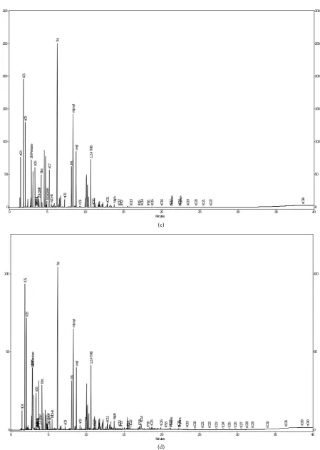
Figure 4 presents two examples of gasoline-range intermediate stream
prod-ucts and similar types of LNAPL. Figure 4(a) is a chromatogram of light
hydro-crackate product, which is the lightest “cut” from ahydrocracking unit. Figure
4(b) is the similar product that was found in groundwater. Figure 4(c) is a
chromatogram of reformate, a type of intermediate stream product from
refor-mer unit. Figure 4(d) is the similar product on groundwater. Note that in the
LNAPL samples, minor amounts of heavier hydrocarbons are also present. These hydrocarbons are from middle distillate intermediate stream(s) known to
be released to the subsurface historically [5]. Weathering was considered to be a
possible mechanism for the presence of heavier hydrocarbons; however, it is not a significant factor in this study area due to the depth of LNAPL occurrence (>50 feet below surface) and the fine grained geological materials (predominantly silt and clay) above the water table.
In this study, comparison between the fresh intermediate stream products and the LNAPLs was made based on the hydrocarbon range and types of major compounds in the samples. The feed stocks used for the refining processes may differ between the current fresh stream and the stream manufactured historical-ly. In addition, weathering may alter relative proportion of the major com-pounds in the LNAPL. However, as a refining process was set up to produce
in-termediate stream products that bear some general characteristics (i.e., the
hy-drocarbon range and types of major compounds), the general similarity of the two aspects, combined with understanding of the site history suffices to relate the LNAPLs to likely refinery intermediate stream products.
J. Lu
(a)
(b)
Minutes
0 5 10 15 20 25 30 35 40
0 250 500
0 250 500
nC
4
iC
5
nC
5
2M
P
ent
ane
nC
6
olef
in c 2,4 D
MP
Bnz
Isoo
ctane nC7MC
HX
To
l
nC
10
Naph IP13 nC39
Minutes
0 5 10 15 20 25 30 35 40
0 250 500
0 250 500
nC
4
iC
5
nC
5
2M
P
ent
ane
nC
6
olef
in a
olef
in b
olef
in c 2,4 DMP
Bnz
Isooc
tane
nC
7 MCHX
To
l
nC
8 EBm/
p-x
yl
o-xy
l
nC
9 1,2,4 T
MB
nC
10 nC11 Naph nC12IP13 IP14 nC13 IP1
5
nC
14 IP16 nC15 nC16 IP18 nC17Prist
ane
nC
18
Phy
tane
nC
19
nC
20
nC
21
nC
22
nC
23
nC
24
nC
25
nC
26
nC
27
nC
28
nC
29
nC
30
nC
31
nC
32
nC
33
nC
34
nC
36
nC
37
nC
38
nC
39
nC
40
J. Lu
(c)
[image:7.595.71.521.59.691.2](d)
Figure 4. Fresh intermediate stream products and similar types of LNAPLs ((a) Light hydrocrackate intermediate stream product; (b) Light hydrocrackate dominated LNAPL; (c) Reformate stream product; (d) Reformate dominated LNAPL). The samples were collected from an anonymous refinery.
Minutes
0 5 10 15 20 25 30 35 40
0 50 100 150 200 250 300
0 50 100 150 200 250 300
nC
4
iC
5
nC
5
2M
P
ent
ane
nC
6
olef
in a
olef
in c 2,4 D
MP
Bnz
Isoo
ctane
nC
7
MC
HX
To
l
nC
8
EB
m/
p-xyl
o-xy
l
nC
9
1,2,
4 T
MB
nC
10 nC11 Naph
nC
12
IP1
3
nC
13
IP1
5
nC
14
IP1
6
nC
15
nC
16
nC
17
Pr
ist
ane
nC
18
Phy
tane
nC
19
nC
20
nC
21
nC
22 nC39
Minutes
0 5 10 15 20 25 30 35 40
0 50 100
0 50 100
nC
4
iC5
nC
5
MT
BE
2M
P
ent
ane
nC
6
olef
in a
olef
in b
olef
in c 2,4 D
MP
Bnz
Isooc
tan
e
nC
7 MCHX
To
l
nC
8
EB
m/
p-xyl
o-x
yl
nC
9
1,2,
4 T
MB
nC
10 nC11 Naph
nC
12
IP
13 IP14 nC13 IP15 nC
14
IP16 nC15 nC16 IP18 nC17Prist
ane
nC
18
Phy
tane
nC
19
nC
20
nC
21
nC
22
nC
23
nC
24
nC
25
nC
26
nC
27
nC
28
nC
29
nC
32 nC36 nC39
nC
J. Lu
wells can significantly alter the groundwater flow directions and therefore com-mingling of LNAPLs could occur and can be complex depending on the types of
LNAPLs and hydrodynamics. In the two LNAPLs shown in Figure 4(b) and
Figure 4(d), commingling is minimal so the predominant component can be identified fairly easily; however, if commingling is substantial, the LNAPL can be similar to “finished gasoline” and therefore distinction between refinery inter-mediate stream products and the finished gasoline becomes more challenging.
4. Differentiation of Commingled Intermediate Stream
Products from a Finished Gasoline
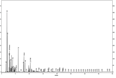
At a subject petroleum refinery, LNAPL was encountered near the property boundary. Historically there were a number of refining processing units includ-ing reformers and hydrocrackers in this area. The LNAPL plume is composed of various product types. In one of the monitoring wells (MW-R), the LNAPL ap-pears similar to the finished gasoline in which there apap-pears to be a blend of high octane components such as aromatics (toluene, xylenes and other alkyl-benzene isomers) and light molecular weight components (C5-) which
arene-cessary to meet RVP requirement (Figure 5). As the well is near the pipeline
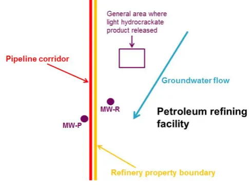
corridor that runs along the refinery property boundary (Figure 6), the LNAPL
[image:8.595.64.540.403.724.2]was thought to be a finished gasoline and sourced from the pipeline(s). Howev-er, detailed examination of the LNAPL hydrodynamics in the area, combined
Figure 5. LNAPL in the well MW-R found in Event 2.
Minutes
0 5 10 15 20 25 30 35 40
0 50 100 150 200 250 300 350 400 450 500
0 50 100 150 200 250 300 350 400 450 500
nC
4
iC
5
nC
5
MTB
E
2M
P
ent
ane
nC
6
olef
in a
olef
in b
olef
in c 2,4 D
MP
Bnz
Isooc
tanenC7 MCH
X
To
l
nC
8
EB
m/
p-x
yl
o-xy
l
nC
9
1,2,
4 T
MB
nC
10 nC11 Naph
nC
12
IP1
3
IP1
4
nC
13 IP15 nC14
IP1
6
nC
15
nC
16
IP1
8
nC
17
Pr
ist
ane
nC
18
Phy
tane
nC
19
nC
20
nC
21
nC
22
nC
23
nC
24
nC
25
nC
26
nC
27
nC
28
nC
29
nC
30
nC
31
nC
32
nC
33
nC
34
nC
36
nC
39
nC
40
J. Lu
Figure 6. Site map.
with chemical characteristics of the LNAPL at MW-R suggests otherwise. Details are discussed in the following sections.
4.1. Commingling of Gasoline Intermediate Stream
Products at MW-R
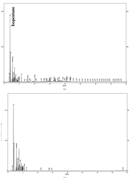
The LNAPL has been sampled from the well MW-R for a number of years for various monitoring purposes. One of the most valuable data relevant to this
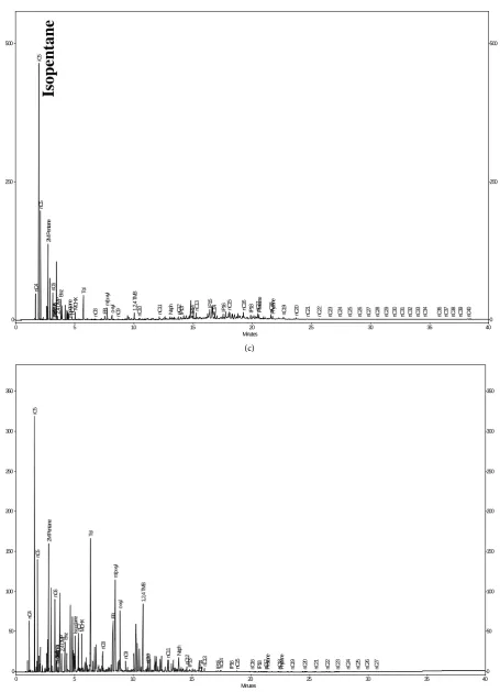
study is the GC/FID chromatograms. Figure 7 shows chromatograms of the
LNAPL from the well. To protect client anonymity, sampling dates are not re-vealed; instead, they are presented sequentially as Event 1, Event 2, and Event 3. Common to all three chromatograms, similar peak patterns exist from the reten-tion time approximately 15 minutes up. This fracreten-tion is known to be a middle distillate refinery intermediate stream (similar to No. 2 diesel). Because the mid-dle distillate is much heavier than the gasoline range products of concern in this study and overlap of the hydrocarbons is minimal, no further discussion is made on the fraction. In the lighter fraction, three chromatograms appear different. The sample in Event 1is a type of gasoline range product rich in aromatics. In Event 2 (three years later), the characteristics of LNAPL changed dramatically, with the isopentane as predominant compound. In Event 3 (two years after Event 2), the product is composed primarily of isopentane and other light
mo-lecular weight compounds
( )
C7− . The marked change in the chemical profile
mandated further investigation.
In the past, reformate stream products were released in the area where refor-mers were located. Release(s) of light hydrocrackate were also documented up
gradient of the reformers within the refinery. Figure 8 shows comparison
be-tween LNAPL samples collected from the wells and fresh refinery intermediate stream products. As can be seen, the Event 1 product resembles reformate and Event 3 product is almost identical to the light hydrocrackate. The Event 2
sam-ple (Figure 7(d)) appears to be a mixture of the two intermediate stream pro-
J. Lu (a) (b) Minutes
0 5 10 15 20 25 30 35 40
0 50 100 0 50 100 nC 4 iC 5 nC 5 MT
BE2M Pent
ane nC 6 olef in a olef in b olef
in c 2,4 DMP
Bnz
Isooc
tane nC7 MCHX
To l nC 8 EB m/ p-x yl o-xy l nC 9 1,2, 4 T MB nC
10 nC11 Naph
nC 12 IP1 3 IP1 4 nC
13 IP15 nC14
IP1 6 nC 15 nC 16 IP1 8 nC 17 Pr ist ane nC 18 Phy tan e nC 19 nC 20 nC 21 nC 22 nC 23 nC 24 nC 25 nC 26 nC 27 nC 28 nC 29 nC
32 nC36
nC 39 nC 40
Is
o
pe
nt
a
ne
T
o
lue
ne
m/
p
-X
y
len
es
1
,2
,4
-t
ri
m
et
h
y
lb
en
zen
e
Minutes0 5 10 15 20 25 30 35 40
0 50 100 150 200 250 300 350 400 450 500 0 50 100 150 200 250 300 350 400 450 500 nC 4 iC 5 nC 5 MT BE 2M P en tane nC 6 olef in a olef in b olef
in c 2,4 D
MP
Bnz
Isooc
tanenC7 MCH
X To l nC 8 EB m/ p-xy l o-xy l nC 9 1,2 ,4 T MB nC
10 nC11 Naph
nC 12 IP1 3 IP1 4 nC
13 IP15 nC14
IP1 6 nC 15 nC 16 IP1 8 nC 17 Pr ist ane nC 18 Phy tane nC 19 nC 20 nC 21 nC 22 nC 23 nC 24 nC 25 nC 26 nC 27 nC 28 nC 29 nC 30 nC 31 nC 32 nC 33 nC 34 nC
36 nC39
J. Lu
(c)
[image:11.595.70.526.63.693.2](d)
Figure 7. GC/FID chromatograms of types of LNAPL found in the well MW-R in Event 1 (a); Event 2 (b) and Event 3 (c) and the well MW-P in Event 2 (d).
Minutes
0 5 10 15 20 25 30 35 40
0 250 500 0 250 500 nC 4 iC 5 nC 5 2M P ent ane nC 6 olef in a olef in b olef
in c 2,4 DMP
Bnz Isooc tane nC 7 MCH X To l nC
8 EBm/
p-xy
l
o-xy
l
nC
9 1,2,4 T
MB
nC
10 nC11
Naph nC12IP13 IP14 nC13 IP1
5
nC
14 IP16 nC15 nC16 IP18 nC17Prist
ane nC 18 Phy tane nC 19 nC 20 nC 21 nC 22 nC 23 nC 24 nC 25 nC 26 nC 27 nC 28 nC 29 nC 30 nC 31 nC 32 nC 33 nC 34 nC 36 nC 37 nC 38 nC 39 nC 40
Is
o
pe
nt
a
ne
Minutes0 5 10 15 20 25 30 35 40
0 50 100 150 200 250 300 350 0 50 100 150 200 250 300 350 nC4 iC 5 nC5 2M P ent ane nC6 olef in a olef in b olef
in c 2,4 D MP Bnz
Iso
oc
tane
nC7 MCHX
To l nC8 EB m/ p-x yl o-x yl nC9 1,2, 4 T MB nC
10 nC11 Nap
h nC 12 IP 13 IP
14 nC13 IP15 nC14 IP16 nC15 nC16
J. Lu (a) (b) Minutes
0 5 10 15 20 25 30 35 40
0 50 100 0 50 100 nC 4 iC 5 nC 5 MT BE 2M P ent ane nC 6 olef in a olef in b olef
in c 2,4 DMP
Bnz
Isooc
tane nC7 MCHX
To l nC 8 EB m/ p-x yl o-xy l nC 9 1,2, 4 T MB nC
10 nC11 Naph
nC 12 IP1 3 IP1 4 nC
13 IP15 nC14
IP1 6 nC 15 nC 16 IP1
8 nC17
Pr ist ane nC 18 Phy tan e nC 19 nC 20 nC 21 nC 22 nC 23 nC 24 nC 25 nC 26 nC 27 nC 28 nC
29 nC32 nC36 nC39 nC40
m/
p
-X
y
len
es
1
,2
,4
-t
ri
m
et
h
y
lb
en
zen
e
T
o
lue
ne
Is
o
pe
nt
a
ne
Minutes M i l l i v o l t s0 5 10 15 20 25 30 35 40
0 50 100 150 200 250 300 0 50 100 150 200 250 300 nC4 iC 5 nC5 2M P ent ane nC6 olef in a olef
in c 2,4 D
MP Bn z Isooc tane nC7 MC HX To l nC8 EB m/ p-xyl o-xy l nC9 1,2, 4 T MB nC
10 nC11 Naph nC12
IP1 3 nC 13 IP1 5 nC 14 IP1 6 nC 15 nC 16 nC 17 Pr ist an e nC 18 Phy tane nC 19 nC 20 nC 21 nC
J. Lu
(c)
[image:13.595.70.524.62.687.2](d)
Figure 8. Comparison of LNAPLs found in the well MW-R and refinery intermediate stream products ((a) LNAPL collected in Event 1; (b) Reformate intermediate stream product; (c) LNAPL collected in Event 3; and (d) Light hydrocrackate intermediate stream product).
Minutes
0 5 10 15 20 25 30 35 40
0 250 500
0 250 500
nC
4
iC
5
nC
5
2M
P
ent
ane
nC
6
olef
in a
olef
in b
olef
in c 2,4 DMP
Bnz
Isooc
tane
nC
7 MCH X To
l
nC
8 EBm/
p-xy
l
o-xy
l
nC
9 1,2,4 T
MB
nC
10 nC11
Naph nC12IP13 IP14 nC13 IP1
5
nC
14 IP16 nC15 nC16 IP18 nC17Prist
ane
nC
18
Phy
tane
nC
19
nC
20
nC
21
nC
22
nC
23
nC
24
nC
25
nC
26
nC
27
nC
28
nC
29
nC
30
nC
31
nC
32
nC
33
nC
34
nC
36
nC
37
nC
38
nC
39
nC
40
Is
o
pe
nt
a
ne
Minutes M
i l l i v o l t s
0 5 10 15 20 25 30 35 40
0 250 500
0 250 500
nC4
iC
5
nC5
2M
Pent
an
e
nC6
ole
fin c 2,4 D
MP
Bn
z
Isoo
cta
ne
nC7
MC
HX
To
l
nC
10
Nap
h
IP
13 nC39
J. Lu
The trend of the pattern change of the chemical components in the LNAPL in the consecutive events appears to indicate that the LNAPL at the well MW-R contains increasingly higher component of light hydrocrackate. This change ap-pears to be consistent with the timing of release of light hydrocrackate (a few years prior to the time of Event 1) upgradient of the reformate LNAPL and mi-gration of the light hydrocrackate toward the well MW-R in the direction of groundwater flow. In the area of MW-R, initial LNAPL was predominantly composed of reformate. In Event 1, the hydrocrackate LNAPL had not reached the reformate LNAPL yet and therefore the LNAPL is predominantly composed of reformate. In Event 2, light hydrocrackate from the upgradient source
com-mingled with reformate. As shown in Figure 8, reformate is low in light
mole-cular compounds relative to toluene; however, the addition of light hydrocrack-ate changed the pattern so the relative proportion of these two components be-come similar to those of finished gasoline. In Event 3, the original reformate LNAPL area appears to be dominated by a peak flow of light hydrocrackate, so the LNAPL in the area is predominantly light hydrocrackate.
To verify the conclusion from analysis based on LNAPL hydrodynamics, ratio analysis was conducted. Use of ratios of compounds is beneficial because with ratios concentration effects are minimized. In addition, the use of ratios tends to induce a self-normalizing effect on the data since variations due to fluctuations of instrument operating conditions, operator and matrix effects are minimized
[4][5]. For source identification or correlation between LNAPLs that have been
subject to environmental alteration, the paired compounds ideally should have a similarvapor pressure, water solubility and rate of biodegradation as these are the predominant alteration mechanisms controlling LNAPL degradation in soil and groundwater.
From GC/FID analysis, relative concentrations of 89 compounds are available from laboratory reports. Of these, approximately 40 compounds are in gasoline range. Of the 40 compounds, most of them are alkylbenzene isomers. As de-scribed, the Event 3 LNAPL is predominantly composed of light hydrocrackate which contains few eligible compounds for ratio analysis and therefore is ex-cluded. The analysis was only conducted for the samples collected in Event 1 and Event 2. For the ratio analysis, only isoalkane and aromaticisomers are consi-dered for the reasons stated above. Out of 11 compounds, six ratios are
[image:14.595.210.541.629.735.2]generat-ed and presentgenerat-ed in Table 1.
Table 1. Ratios of selected hydrocarbon compounds.
Ratios MW-R-E1 MW-R-E2 MW-P-E2
2-Methylpentane/3Methylpentane 1.88 1.88 1.60
2-Methylhexane/3Methylhexane 1.42 1.55 1.41
m/p-Xylenes/o-Xylene 2.85 2.89 2.09
J. Lu
As can be seen from Table 1, six ratios are identical between Event 1 and
Event 2. The identical ratios suggest that the hydrocarbons in the two samples are source related and support the conclusion drawn previously.
4.2. Characteristics of the Finished Gasoline near the
Pipeline Corridor
As described previously, a pipeline corridor runs along the refinery property boundary. During a routine groundwater monitoring event, gasoline product was present in a monitoring well (MW-P) near the boundary of a refinery facili-ty (Figure 6). In the vicinity, only a gasoline-range LNAPL plume is represented
by the LNAPL at MW-R. Figure 9 shows chromatograms of LNAPLs from both
wells. On a cursory review, the LNAPLs appear similar. The lower concentration of isopentane relative to the aromatics in the MW-P could be a result of prefe-rential depletion of isopentane due to evaporation. In fact, the LNAPL from the MW-P was claimed to be sourced from the refinery by a previous worker based on similarity of chromatographic patterns. To understand the source relation-ship of LNAPL from the two wells, detailed chemical fingerprints are examined and comparisons made with the LNAPL from the well MW-R.
4.2.1. Lead Additive
The LNAPL from the well MW-P contains organic lead (54 parts per million [ppm]), while the LNAPL from MW-R lacksorganic lead (non-detect at report-ing limit of 0.5 ppm). It isunlikely the lead was sourced from the LNAPL represented by the sample from MW-R. Assuming that the LNAPL migrated from the area at or near MW-R to MW-P, the concentration of organic lead may either show little change in case of a massive LNAPL plume, or become depleted
due to sorption to soils and biological and chemical processes [6][7][8][9][10].
It is possible that lead may be concentrated through preferential evaporation as the vapor pressures of lead species are lower than the light fraction of gasoline range hydrocarbons. However, this is unlikely due to deep occurrence of LNAPL as described previously. Presence of lead in the MW-P LNAPL suggests that the MW-P LNAPL is likely a leaded gasoline, but the lead content alone cannot rule out the possibility of partial contribution of MW-R LNAPL to the MW-P LNAPL.
4.2.2. Isooctane Content
As can be seen from Figure 9, isooctane is present in the LNAPL from well
MW-P. It is possible that an alkylate LNAPL was commingled with the gasoline product at the MW-P or a component of finished gasoline intentionally blended to increase octane number. As there is no LNAPL in the vicinity that contains isooctane (including the LNAPL from the well MW-R), it is likely that the isooctane is associated with finished gasoline.
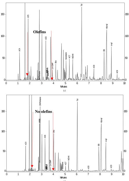
4.2.3. Olefin Content
J. Lu 729 (a) (b) Minutes
0 5 10 15 20 25 30 35 40
0 50 100 150 200 250 300 350 0 50 100 150 200 250 300 350 nC4 iC 5 nC5 2M P ent ane nC6 olef in a olef in b olef
in c 2,4 D MP Bnz Iso
oc
tane
nC7 MCHX
To l nC8 EB m/ p-x yl o-x yl nC9 1,2, 4 T MB nC
10 nC11 Nap
h nC 12 IP 13 IP
14 nC13 IP15 nC14 IP16 nC15 nC16
IP
18 nC17
Pr ist ane nC 18 Phy tan e nC 19 nC 20 nC 21 nC 22 nC 23 nC 24 nC 25 nC 26 nC 27
Minutes
0 5 10 15 20 25 30 35 40
0 50 100 150 200 250 300 350 400 450 500 0 50 100 150 200 250 300 350 400 450 500 nC 4 iC 5 nC 5 MT BE 2M P en tane nC 6 olef in a olef in b olef
in c 2,4 D
MP
Bnz
Isooc
tanenC7 MCH
X To l nC 8 EB m/ p-xy l o-xy l nC 9 1,2 ,4 T MB nC
10 nC11 Naph
nC 12 IP1 3 IP1 4 nC
13 IP15 nC14
J. Lu
730
(c)
[image:17.595.75.520.63.687.2](d)
Figure 9. Contrast of olefin content in the LNAPL from the well MW-P and MW-R ((a) LNAPL from the well MW-P; (b) LNAPL from the well MW-R; (c) Expanded chromatogram of the LNAPL from MW-P; (d) Expanded chromatogram of the LNAPL from MW-R).
Minutes
0 1 2 3 4 5 6 7 8 9 10
0 50 100 150 0 50 100 150 nC4 iC 5 nC5 2M P en tan e nC6 olefi n a olefi n b olefi n c 2,4 D MP Bn z Isoo ctane
nC7 MCHX
To l nC8 EB m/ p-xyl o-xyl nC9
Olefins
Minutes
0 1 2 3 4 5 6 7 8 9 10
0 50 100 150 0 50 100 150 nC4 iC 5 nC5 MT BE 2M P en ta ne nC6 olefi n a olefi n b olefi
n c 2,4 DM
J. Lu
of MW-P product, abundant olefins are present after nC6 and nC7 (numerous
peaks) (Figure 9). However, in the chromatogram of MW-R product, olefins are
either low or absent. The absence of olefins in the MW-Rindicates that the product is blended with refinery intermediate stream products by non-cracking processes except for hydrocracking, while the olefins-rich MW-P product con-tains an intermediate stream product that was derived from cracking processes such as fluidized catalytic cracking, thermal cracking, etc.
Olefins are known to be an unstable group of hydrocarbons due to their high
reactivity as compared hydrocarbon types [11]. It is apparent that the olefins in
MW-P product unlikely sourced from the MW-R product. This is because the olefins may become depleted during migration, but cannot be generated during migration.
4.2.4. Ratios
Ratios of selected compounds described previously were also used for
compari-son purposes. As can be seen from Table 1, among the six ratios, three of them
(i.e, 2 methylpentane/2-methylpentane, m/p-xylenes/o-xylene and 1,2,4-trime-
thybenzene/1,2,3-trimethylbenzene) show significant differences among LNAPL samples (12% to 28%).
Each set of fingerprints presented above revealed some specific chemical cha-racteristics of the LNAPL; collectively, the information obtained appears suffi-cient to conclude that the LNAPL from the well MW-P is a type of finished gas-oline and sourced from the pipeline(s). The MW-R LNAPL is a result of
com-mingling of two major gasoline intermediate stream products (i.e., reformate
and light hydrocrackate) and not source-related to the MW-P LNAPL.
5. Concluding Remarks
J. Lu
Acknowledgements
The author would like to thank Kim Olsen for her editing and formatting of text, tables and figures.
References
[1] Speight, J.G. (1991) The Chemistry and Technology of Petroleum. 2nd Edition, Marcel Dekker, Inc., New York.
[2] Leffler, W.L. (2008) Petroleum Refining in Non-Technical Language. 4th Edition, PennWell Corporation, Tulsa.
[3] Weaver, J.W., Charbeneau, R.J., Tauxe, J.D., Lien, B.K. and Provost, J.B. (1994) The Hydrocarbon Spill Screening Model (HSSM). Volume 1, User’s Guide, EPA/600/ R-94/039a.
[4] Wang, Z.D. and Christensen, J.H. (2006) Crude Oil and Refined Product Finger-printing: Applications. Environmental Forensics—Contaminant Specific Guide, In: Morrison, R.D. and Murphy, B.L., Eds., Academic Press, Amsterdam.
[5] Lu, J. (2011) Chapter 8: Application of Statistics in Environmental Forensics of Fingerprinting Light Non-Aqueous Phase Liquid Data Analysis. Practical
Applica-tions of Environmental Statistics and Data Analysis, ILM Publications.
[6] Mansell, R.S., Ou, L., Rhue, R.D. and Ouyang, Y. (1995) The Fate and Behavior of Lead Alkyls in the Subsurface Environment: Final Tech. Rpt. To Armstrong Labor-atory, Tyndall, Air Force Base, Battelle Memorial Institute, 102.
[7] Kaplan, I.R., Galperin, Y., Lu, S.T. and Lee, R.-P. (1997) Forensic Environmental Geochemistry: Differentiation of Fuel-Types, Their Sources and Release Time.
Or-ganic Geochemistry, 27, 289-317. https://doi.org/10.1016/S0146-6380(97)87941-7
[8] Mulroy, P.T. and Ou, L.-T. (1998) Degradation of Tetraethyllead during the Degra-dation of Leaded Gasoline Hydrocarbons in Soil. Environmental Toxicology and
Chemistry, 17, 777-782. https://doi.org/10.1002/etc.5620170502
[9] Morrison, R.D. (2000) Critical Review of Environmental Forensic Techniques: Part
II. Environmental Forensics, 1, 175-195. https://doi.org/10.1006/enfo.2000.0018
[10] Stout, S.A., Douglas, G.S. and Uhler, A.D. (2007) Chapter 18, Automotive Gasoline.
Oil Spill Environmental Forensics—Fingerprinting and Source Identification,
Aca-demic Press, San Diego.
Submit or recommend next manuscript to SCIRP and we will provide best service for you:
Accepting pre-submission inquiries through Email, Facebook, LinkedIn, Twitter, etc. A wide selection of journals (inclusive of 9 subjects, more than 200 journals)
Providing 24-hour high-quality service User-friendly online submission system Fair and swift peer-review system
Efficient typesetting and proofreading procedure
Display of the result of downloads and visits, as well as the number of cited articles Maximum dissemination of your research work
Submit your manuscript at: http://papersubmission.scirp.org/

![Figure 3. Schematic view of LNAPL release and mi-gration pathway [3].](https://thumb-us.123doks.com/thumbv2/123dok_us/7747544.709260/5.595.268.475.80.280/figure-schematic-view-lnapl-release-mi-gration-pathway.webp)