Development of Tailored Porous Microstructures for Infiltrated Catalyst Electrodes by Aqueous Tape Casting Methods
M. Cassidy, D.J. Doherty, X. Yue, J.T.S. Irvine
School of Chemistry, University of St Andrews, St Andrews, KY16 9ST, UK
Recent SOFC research has shown that impregnating fine catalyst structures into porous scaffolds to be an extremely promising route for electrode development. It is clear that in optimising the advantages offered by this technique there will be an obvious link between the morphology of the porous scaffold and the infiltrated catalyst. There are significant potential benefits to using aqueous systems for the manufacture of the scaffold. They include the potential for a far larger range of pore formers which may be employed to create specific pore morphologies and also reduced environmental burdens, such as exhaust handling, worker exposure and disposal. Recent and ongoing activities to develop such systems at University of St Andrews will be described. Areas of discussion will be effects of ceramic particle size, the size ratio of pore former to ceramic particle, pore former type and loading and how these interact with other tape constituents both on the behaviour during processing and on the final fired morphology. Better understanding of these complex relationships will help in designing optimised porous structures in the future.
Introduction
Solid Oxide Fuel Cells (SOFC) have long been promising devices for the efficient conversion of chemical to electrical energy. A number of materials such as Ni/YSZ cermet anodes have become industry standard materials they are well established in the technology and the good electrochemical performance of these Ni based cermets have proved difficult to rival (1). However they do suffer from a number of weaknesses which can limit performance and durability, such redox tolerance, carbon deposition in hydrocarbon fuels and sulphur poisoning, though as they have proved difficult to replace a number of engineering solutions have been developed to work around these limitations but they do add cost and complexity to the system in terms of manufacture, operation and maintenance (2). Therefore materials based solutions which could offer a more robust anode with resistance to the above limitations would be of great advantage in simplifying system design and reducing costs and are still sought.
decomposition can both vary depending on the solution and the desired phase. Both anodes and cathodes have been made in this way and both have shown promising results
with 710mWcm-2 at 800°C being demonstrated in relatively dry methane (3% H2O) (3).
However while there has been considerable work on formulating different catalyst phases there has been little systematic work carried out on developing and engineering the scaffold phase to best compliment the infiltrated catalyst.
The scaffold structures will generally form the structural element of the cell and as such the thickness and area ratios lend themselves to processing by tape casting. This technique has been widely employed in SOFC fabrication, most often to form a dense electrolyte membrane for an electrolyte supported cell or as a NiO and ionic conductor mixture that will form a porous cermet anode support or multilayer cell assemblies that are cofired (4, 5). Much of the processing of these tapes also revolves around the use of non-polar organic solvents such as methyl ethyl ketone (MEK) or toluene often mixed with ethanol to form azeotropes. While these mixtures form the basis of good, reliable tape formulations with binders such as PVB the nature of the solvent limits the use of available pore formers to either graphitic or glassy carbons and various starches. In order to widen the possible range of pore formers moving to an aqueous system is an attractive option, while graphites, carbon and some starches are still available as options, acrylic, polystyrene and latex based system also become available. These are available in a range of highly controlled size distributions ranging from single µm through 10’s µm diameter and offer a potential route tailoring the pore shape, size and distribution to best compliment the needs of the infiltrated catalyst.
While aqueous tape casting is not in itself new and has also been applied to SOFC fabrication, this has often been to produce traditional porous electrodes based on bulk porous cermets or dense electrolyte membranes (6, 7). In this work the aim is to investigate the fabrication of more open porous structures as in the scaffolds it is not only the gas diffusion during operation which needs to be considered but also the ability to get the infiltrating solution well distributed evenly throughout the structure, preferably without the need for additional processing steps such as drawing with vacuum. The ideal structure would be well balanced to the viscosity of the impregnation solution such that the latter is drawn deep into the structure by capillary forces.
However aqueous tape casting is not without its challenges, one of the reasons up take of this technique had been slow is perception of difficulty in the process control and poor reproducibility. This is in large part due to the polar nature of water as a solvent and the increased level of interactions between powders, binders, pore formers and other tape components through intermolecular forces such as hydrogen bonding. In this paper initial studies into the behavior of a number of pore forming options in an aqueous YSZ tape are investigated and results are discussed with respect to effects on tape viscosity for casting and the final microstructure once fired.
Experimental
Raw Materials
and a 3-5µm (3-5 µm), with the first two graded to have particles below the specified size and the third graded to within the specified limits. Figure 1 shows the particle size distributions (measured on a Malvern Mastersizer 2000) of the 3 powders after ball milling for 18 hours, which is representative of the first milling stage. It can be seen that all three powder are finer than their specified grades would suggest, although the 2 and -10 are below their stated sizes. The 3-5 micron is not within the graded size range, however it does have the largest d10, d50 and d90 of the three grades, at 0.49µm, 1.14µm
[image:3.612.91.524.234.338.2]and 2.62µm respectively. Although one must consider the milling action will break down agglomerates and maybe some particles, along with potential for sampling error of a few mg for test from a few Kg powder batch. Also the means of grading the powder at the manufacturers is as yet unknown and different methods (say dry sieving) may skew results slightly due to a greater tendency for agglomeration in these states.
Figure 1. Particle size distributions for the three 8YSZ powders after 18 hours ball milling.
Three main pore formers were applied in this study. These were rice starch (Sigma) and two forms of acrylic microspheres based on poly(methyl methacrylate-co-ethylene glycol dimethacrylate) (PMMA) and poly(ethyl methacrylate) (PEMA) (both Sigma) and graded as 8µm and 35-45µm respectively. Table 1 shows the size distribution figures for these three materials. This shows the rice starch and the PMMA to be similarly sized with the PEMA significantly larger, as suggested by its specification. Pore formers were used singly and in combination. Pore former additions were considered as a volume fraction and this was calculated with respect to the volume of the dry green tape with all water removed as the amount of water will vary between tapes to attain a viscosity suitable for casting which is influenced by the surface area of all the solid constituents.
Table 1 Particle size values for the pore formers used in this study
Pore Former d10 d50 d90
Rice Starch 1.42 5.34 10.69
PMMA 0.95 5.85 10.56
PEMA 9.42 33.38 89.17
Casting Process
The casting process was an aqueous process using deionised water as the principle solvent with Hypermer KD6 as dispersant, polyvinyl alcohol, as the binder, glycerol and polyethylene glycol as plasticisers. Ceramic and pore formers were first milled in water with KD6 to deagglomerate the particles and ensure good dispersions and coating with dispersant. The remaining organics were then added along with 2,4,7,9 tetramethyl(5-decyne)4,7 diol ethoxylate as a defoamer, followed by continued milling at a slightly
-2µm
-10µm
[image:3.612.89.452.553.608.2]reduced speed to homogenise the slurry. Following this the slurry was slow rolled overnight before casting to de-air before casting.
The slurry was cast using a bench top caster with a steel doctor blade onto a moving Mylar carrier film. The casting gap was set to 750µm and after casting the slurry was allowed to dry in ambient air on the casting bed. Dry tapes were fired between porous alumina plates in air at a temperature of 1400°C for 2 hours. Temperature ramp rates were controlled at 1°Cmin-1 during organic burn out and at 3°Cmin-1 at other times.
Analysis Techniques
Rheological measurements were carried out using a Brookfield DVIII+ rheometer with a small sample adapter. This was controlled and data recorded and analysed through the Rheocalc software supplied by Brookfield. Measurements were carried out a 20-22°C which are ambient conditions in the tape casting laboratory. Specimens were allowed to rest for one minute before test commenced in which a standard shear protocol was followed.
Scanning Electron Microscopy (SEM) images were captured on a Jeol JSM 5600 using secondary electrons. Both fracture and polished surfaces were examined. On the latter tapes were impregnated with epoxy resin before curing and polishing to a 1µm diamond finish. Polished sections were analysed with “Image J” software. First SEM images were captured with high contrast to differentiate between the resin and the ceramic struts of the scaffold. The captured image was then cropped to a reasonable sized area of interest, length scale calibrated and a threshold value set with respect to the porous areas of the image. This was then used to calculate percentage area of the image as porosity.
Results and Discussion
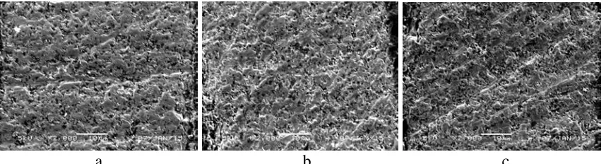
Figure 2 shows micrographs of fired tapes made from the 3 zirconia powders with no pore former addition. From these images it can be seen that the 3-5µm appears to have marginally more porosity that the -2µm or the -10µm This is confirmed by porous area analysis shown in Table 2 and is in line with the particle size data for the milled powder with the -2µm and the -10µm powders showing a more significant fine particle fraction than the 3-5µm powder.
[image:4.612.91.523.577.692.2]a b c
Table 2. Particle size values for the pore formers used in this study Powder Av. Pore Size(µm) Pore Area (%)
-2µm 0.03 0.5
3-5µm 0.10 6.5
-10µm 0.05 2.3
Rice starch was added to the -2µm zirconia tape at three volumetric ratios of YSZ to rice starch, 90:10, 80:20 and 70:30. This powder was selected for this trial as it had given the least favorable porosity and it was of interest to see how the addition of pore former affected this. Figure 3 and Table 3 show the microstructures and quantification of these respectively. The addition of the rice starch did significantly increase the porosity within the tape with the average pore size increasing from 0.03 to close to 0.5µm with a significant number of larger pores, when one only considers pore sizes above 0.25µm (more likely to have come from pore former burn out rather than from inherent natural porosity of the ceramic) the average is closer to 1µm.
a b c
Figure 3. Micrographs of -2µm YSZ tapes with ceramic to starch ratios of (a) 90:10 (b) 80:20 and (c) 70:30.
Table 3. Quantification of microstructural data from Figure 3.
Observations YSZ: Rice Starch Ratio
90:10 80:20 70:30
Average Pore Size
All pores included 0.44 µm 0.54 µm 0.50 µm
Only Pores > 0.25 µm 0.93 µm 1.13 µm 1.11 µm
Total Pore % of Tape Area 13% 17% 15%
Tape Shrinkage 26.7% 30.0% 35.0%
These results also suggested an optimum porosity with a pore former addition of around 80:20 above which excessive shrinkage of the tape was noted causing dimensional instability during firing. However from visual inspection of the micrographs the observed porosity was not as high as would be preferred for infiltration.
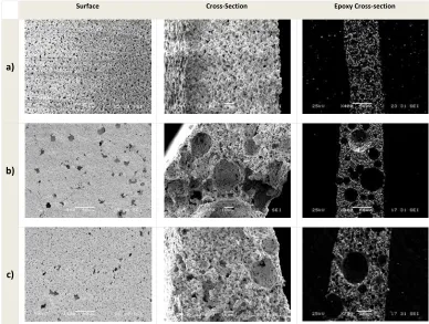
[image:5.612.92.521.273.389.2]Figure 4 shows a representation of the microstructures for both the large and small acrylic microspheres at 30 and 50 vol% addition. The large increase in porosity is immediately apparent with % area of porosity in the region of 48-51% for lower loadings at 30vol% and up to 75-80% for higher pore former loadings of 50 vol%. Of further interest are the templating effects from the pore formers with the effects of the large pores being obvious.
Surface Cross-Section Epoxy Cross-section
a)
b)
c)
d)
Figure 4. SEM surface, fracture surfaces and polished cross-sections of the acrylic pore former tapes. All samples contained 14 vol% rice starch as a reinforcing filler: a) 30 vol% 8 µm PMMA b) 50 vol% 8 µm PMMA c) 30 vol% 35-45 µm PEMA and d) 50 vol% 35-45 µm PEMA
seeing a reduction in the level of non-Newtonian behavior suggesting less structure in the system. Similar effects are observed in the smaller spheres with the reduction in the non-Newtonian behavior appearing at even lower loadings, possibly linked to surface area or particle number effects.
0.000 50.000 100.000 150.000 200.000 250.000
0.03 0.30 3.00 30.00
V
is
cos
it
y
(
P
a
s
)
Shear Rate (s-1)
No starch50% PEMA
30% PEMA
40% PEMA
50% PEMA
[image:7.612.125.503.123.321.2]. Figure 5. Rheological behavior of PEMA containing slurries with and without rice starch addition.
The real effects of this are that the gains in robustness from the rice starch are not quite as hoped, especially at higher pore former loadings. This is compounded by a further effect of the high levels of porosity, in that the remaining skeletal structure becomes weak and difficult to handle once fired. To attempt to mitigate both of these issues a further developmental strategy was adopted. To improve robustness in the green state a further binder was added, styrene acrylic latex. In the wet state this remains as a discrete particle, however on drying it coagulates to form an extra binder phase, in addition to the PVA, within the matrix of the green tape. The aim of this will be to add further toughness to the green tape by the addition of the second binder phase complimenting the existing properties of the PVA.
Secondly the YSZ phase was swapped for a far finer particle size distribution, in this case Daiichi HSY8 with a d50 of around 0.7µm. As the work above has shown that the
HEAT
[image:8.612.206.402.54.222.2]HEAT
Figure 6. Schematic representation of effect of ceramic to pre former size ration on microstructure.
Surface Cross-Section Epoxy Cross-section
a)
b)
c)
Figure 7. SEM surface, fracture surfaces and polished cross-sections of 0.7µm HSY8 with mixed pore formers: a) 30 vol% 8 µm PMMA, 14 vol% rice starch, 20 vol% latex b) 30 vol% 35-45 µm PEMA, 14 vol% rice starch, 20 vol% latex c) 15 vol% 8 µm PMMA, 15 vol% 35-45 µm PEMA, 14 vol% rice starch, 20 vol% latex
Table 4. Percentage Area porosities for the 0.7 µm YSZ scaffolds
0.7 µm YSZ Formulations % Area
Porosity
30 vol% 8 µm PMMA, 14 vol% rice starch; 20 vol% latex 62.2%
30 vol% 35-45 µm PEMA, 14 vol% rice starch; 20 vol% latex 69.9%
[image:8.612.110.498.268.561.2]From the micrographs the microstructures from the 0.7µm YSZ are very encouraging
with a good mixture of large and fine porosity. From the three levels of pore former addition trialed the ability to potentially manipulate the levels of porosity can be observed. It is of interest to note that when the individually sized pore formers are used the areas of porosity are higher than when when a bi-modal size composition is employed where there is a significant drop in the % area of porosity. A related effect is seen in the firing shrinkage. The lowest shrinkage is observed when the 35-45µm PEMA is used on its own at around 13% , when the 8µm PMMA is used the shrinkages are higher tracking with the level in the tape, around 35% in the single 30vol% PMMA and 28% when used at the 15vol% PMMA in conjunction with the larger PEMA microsphere. This is likely related both to packing of the pore formers and ceramic and the subsequent particle movement and rearrangement during burn out and sintering phases. However although promising, there are still issues with fragility of the fired structures and some issues with green strength on which further work and development is required
Overall this work shows there is potential to optimise the ratios of fine and coarse porosity within the structure. This could allow high levels of infiltrating solution to be carried into the structure through the coarse pores so allowing a greater mass of precursor to be deposited in each infiltration cycle thereby reducing the amount of cycles required. The finer porosity still remains to support the final catalyst structures on a high surface area scaffold so retaining high levels of electrochemical performance. In operation the large porosity will allow easy transport of reactant and products gases in and out of the structure so minimizing diffusion losses. Similarly the shrinkage variation observed could be of use in the design of multi-layer structures where managing and matching shrinkages are as important as the microstructures.
Conclusions
Aqueous tape casting systems have been investigated with a view to making porous structures where the porosity can be controlled both in terms of size and morphology. By using a number of fugitive pore formers based on acrylic microspheres and starch particles a variety of porous structures have been created. The work has also shown a strong interaction between the starch and the PVA binder through hydrogen bonding which aids the green strength of the tape, however the effects of this is influenced by the presence of other pore formers in the system and complex interactions exist governing the green properties, shrinkages and fired structures. As these interactions continue to be explored and become better understood they will be important to further optimize the tape cast structures for improved processing, performance and durability. Future work will look to infiltrate catalyst solution into a number of these structures to assess how electrochemical performance tracks with the microstructure to inform further optimisation as well as further development of more complex multilayer structures.
Acknowledgments
References
1. A. Atkinson, S. Barnett, R. J. Gorte, J. T. S. Irvine, A. J. McEvoy, M. Mogensen,
S. C. Singhal and J. Vohs, Nature Materials, 3, 17-27, (2004).
2. A. Faes, A. Hessler-Wyser, A. Zryd and J. Van herle, Membranes, 2, 585-664 (2012).
3. G. Kim, G. Corre, J. T. S. Irvine, J. M. Vohs, R. J. Gorte, Electrochem. and
Solid-State Letters, 11 (2), B16-B19, (2008).
4. S-H Lee, G.L. Messing, M. Awano, J. Am. Ceram. Soc., 91 [2], 421–427 (2008).
5. M. Cassidy, P. Connor, M. Etches, Y. Kalecheff, M. MacHado, J. Nairn, J. Irvine,
Advances in Science and Technology, 87, 98-104 (2014).
6. D. Hotza, P. Greil, Materials Science and Engineering, A202, 206-217 (1995).
7. D. Montinaro, V.M. Sglavo, M. Bertoldi, T. Zandonella, A. Aricò, M. Lo Faro, V.
Antonucci, Solid State Ionics, 177, 2093–2097 (2006).