Reduction of Functionally Graded Material Layers for Si
3N
4-Al
2O
3System
Using Three-Dimensional Finite Element Modeling
Jae Chul Lee
3, Jong Ha Park
1, Sae Hee Ryu
1, Hyun Jung Hong
1;2,
Doh Hyung Riu
2, Sung Hoon Ahn
3and Caroline Sunyong Lee
1;*1Division of Materials and Chemical Engineering Hanyang University, Kyunggi-do, 426-791, Korea 2Korea Institute of Ceramic Engineering and Technology, Seoul, 153-801, Korea
3School of Mechanical and Aerospace Engineering and Institute of Advanced Machinery and Design,
Seoul National University, Seoul, 151-742, Korea
Numerical analysis method was used to reduce the number of functionally graded material (FGM) layers for joining Si3N4-Al2O3using polytypoid interlayer by estimating the position of crack. In the past, hot press sintering of multi-layered FGMs with 20 layers of thickness 500mmeach have been fabricated successfully. In this paper, thermal residual stresses were calculated using finite element method (FEM) to find the optimized number of layers and its thicknesses of FGM joint. The number of layers for FGM was reduced to 15 layers from 20 layers. Thicknesses were varied to minimize residual stresses within the layers while reducing the number of FGM layers. The damage caused by thermal residual stress was estimated using maximum principal stress theory and maximum tensile stress theory. The calculated maximum stress was found to be axial stress of 430 MPa around 90% 12H/10% Al2O3area. For each case, calculated strength of each FGM layer by linear rule of mixture was compared with computed thermal residual stresses. Thermal analysis results correctly predicted the position of crack, and this position agreed well with fabricated joints. Therefore, this numerical analysis method can be applied to reduced FGM layers of crack free joint. Finally, new composition profile of crack free joint was proposed using FGM method. [doi:10.2320/matertrans.MRA2007319]
(Received December 11, 2007; Accepted February 4, 2008; Published March 25, 2008)
Keywords: functionally graded material (FGM), finite element method (FEM), thermal residual stress, linear mixture rule, maximum tensile stress theory, maximum principal stress theory
1. Introduction
Joining is an important process where its commercial and technological studies have been done extensively. One of the reason for joining is the existence of physical and economic limitations for the manufacture of large parts. For fabrication of complex shapes, it must be easier to make regular geometric shapes and join them.1,2)Finally, having different
materials at different regions of the same component is desirable for several applications such as turbine blades, engines and thermal barrier coatings. Moreover, joining makes it possible to exchange only the damaged parts so that the life cycle for the overall parts can be increased and these components can be replaced where recycle would have been difficult.
Fine ceramic parts have been considered as one of the most promising structure materials due to the following unique properties – oxidation and corrosion resistance, thermal stability, and high strength and hardness. However, it is difficult to fabricate complex and large parts based on these properties. Therefore, ceramic joining has been an alternative solution to replace damaged parts and to be able to use fine ceramics for the high temperature applications. Among various joining techniques, joining using functionally graded layers can be an effective technique when joining dissimilar ceramics where there is a big difference in coefficient of thermal expansion (CTE) between the two materials. The functionally graded material (FGM) bonding has a continu-ous change in composition and microstructure from one side to the other, with a corresponding compatible gradient of thermal expansion properties, resulting in a potentially
effective joining of ceramics with widely CTEs. This concept has been used successfully in sialon polytypoidal functional gradient joining of dissimilar ceramics, Si3N4 and Al2O3, described in Ref. 3). A gradual change in thermal expansion mismatch minimizes the thermal stresses arisen from cooling or heating. Therefore, FGMs offer solution to the thermal stress problem and have created wide interest recently.4–9)
In this paper, joining of Si3N4 and Al2O3 using sialon polytypoidal functional gradient joining was demonstrated with fewer functionally graded layers for optimization. Previously, joining of Si3N4 and Al2O3 with polytypoidal functional gradients was successfully demonstrated with hot press sintering of FGM with 20 layers.3)However, these 20
layers are not optimized while reducing number of layers are desirable with minimum residual stress. Various analysis programs were used to calculate residual stresses of various number of layers of FGMs.10,11)In this paper, finite element method was used to obtain reduced and optimized function-ally graded layers by calculating its residual stresses. Compositions and layer thicknesses were varied according to the calculations. These analysis results were compared with the fabricated sample to see whether the actual crack positions matched the computed maximum stress point. Finally, the numerical analysis method to predict the position of the crack was used to design new composition profile of crack free joint with 15 layers.
2. Experimental Procedures
2.1 Material fabrication
To create FGMs, a ‘‘mixture rule’’ was applied to make the gradient since it has been widely used in the modeling of FGMs as shown in the paper by Leeet al.3)
*Corresponding author, E-mail: [email protected]
FGM was fabricated by the following method; first, powders of each composition were mixed in isopropanol solvent, and then powders were agitated using the ultra-sonicator to prevent agglomeration. Si3N4 powders from Grand C&M with a particle size ranging from 0.3mm to 0.5mm were used, and Al2O3 powders from Tamicron industries with the particle size ranging from 0.16 to 0.3mm were used. 12H sialon polytypoid powders were obtained from Novel Technologies. 3 mass% Y2O3was used as sintering additive for polytypoid powders.3) These
powders were dried, sieved, and were stacked layer by layer. The green body was pressed using a cold press to maintain a cylindrical shape. The green body was sintered using a Hot Press in flowing N2 gas to prevent decomposition of Si3N4. The sample was subsequently hot-pressed at 45 MPa, heating up to 1700C for two hours, and then furnace-cooled to room temperature at 2C/min as shown in the heating curve
(Fig. 1). Optical micrographs were used to locate cracks at the cross section of the sample as shown in Fig. 2.
2.2 Calculation of thermal residual stress
The thermal stresses of this FGM geometry were computed taking into account of both CTE and elastic modulus variation of the multitude of joining layers. As shown in Fig. 3, the sample is three-dimensional cylindrical shape where this has been transformed to two-dimensional
axisym-metric model. While considering both CTE and elastic modulus variation of the multitude of joining layers, the linear rule of mixture was applied to make the gradient since it has been widely used in the modeling of FGMs.10–12)
Fig. 1 Heating and cooling profile of hot press during sintering.
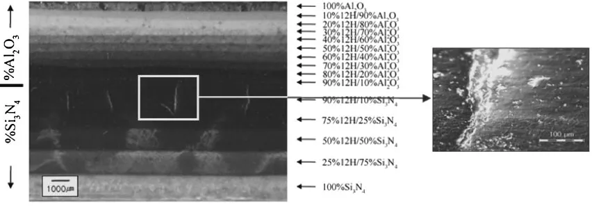
Fig. 2 Cross section of 15-layer Si3N4-Al2O3 FGM using optical micrograph. Right picture shows magnified view of cracks at higher magnification.
Fig. 3 Sample geometry and coordinate systems.
[image:2.595.306.546.71.289.2] [image:2.595.86.512.406.554.2] [image:2.595.83.514.605.770.2]Ec¼v1E1þv2E2 ð1Þ
c¼v11þv22 ð2Þ
Where Ec and c are elastic modulus and CTE of com-posite, respectively. v1 and v2 are the volume fraction of phases 1 and 2, respectively, and v1þv2¼1. The residual stresses were computed with an FEM: ANSYS program.13) Two-dimensional axisymmetric model had 46,981 nodes and 15,494 elements by meshing up to element size of 0.1 mm. The type of element used is two-dimensional 8-node plane element (PLANE82). Figure 4 shows element condition, boundary condition, and PLANE82 element configuration that were used to analyze the residual stress. Table 1 lists the material properties used to calculate the stress. The material composition is taken to be constant in both the radial and circumferential directions. Table 2 lists the composition, weight of each layer, density, and calculated thicknesses used for numerical analysis of FGM model. The residual stresses were assumed to be generated during cooling stage when sintered temperature of 1700C
was dropped to 25C. Thus, 1675C drop of temperature was applied as the thermal loading to the FEM for residual stress calculations.
2.3 Failure criteria
Generally, when material is ductile, von-Mises stress theory can be used to determine whether or not the fracture will occur within a sample. However, ceramics and glasses fracture without any deformation once it goes beyond yielding point. Therefore, ceramics are brittle materials where they fracture without any plastic deformation. There are two types of evaluation method that can be used for brittle materials: Maximum tensile stress theory and Maximum principal stress theory.
2.3.1 Maximum tensile stress theory13)
[image:3.595.111.483.81.270.2]Since brittle materials are generally weaker in tensile yielding strength than in compressive yielding strength, Fig. 4 (a) Element condition and boundary condition and (b) PLANE82 geometry configuration.13)
Table 1 Physical Constants for the materials used for numerical analysis.3Þ
Elastic Modulus C. of Thermal Expansion
E(MPa) (106)
Si3N4 3.30E+5 3.6
Polytypoid 2.90E+5 5.6
Al2O3 3.90E+5 8.8
Poisson’s Ratio Tensile Strength
v (MPa)
Si3N4 0.22 800
Polytypoid 0.22 350
Al2O3 0.22 300
[image:3.595.46.290.325.540.2]ref. 15) ref. 16) ref. 17)
Table 2 Weight of each layer, density calculated by linear mixture rule, and thickness computed by the density used to predict the crack position in the numerical analysis for the FGM sample.
Weight of Density calculated Calculated Composition
each layer (g) by linear rule ofmixture (g/cc) thickness(cm)
Si3N4100% 2.0 3.17 0.12
Si3N475%+Polytypoid 25% 2.0 3.18 0.12
Si3N450%+Polytypoid 50% 2.0 3.19 0.12
Si3N425%+Polytypoid 75% 2.0 3.19 0.12
Si3N410%+Polytypoid 90% 2.0 3.20 0.12
Al2O310%+Polytypoid 90% 1.0 3.28 0.06
Al2O320%+Polytypoid 80% 1.0 3.35 0.06
Al2O330%+Polytypoid 70% 1.0 3.43 0.05
Al2O340%+Polytypoid 60% 1.0 3.50 0.05
Al2O350%+Polytypoid 50% 1.0 3.58 0.05
Al2O360%+Polytypoid 40% 1.0 3.66 0.05
Al2O370%+Polytypoid 30% 1.0 3.73 0.05
Al2O380%+Polytypoid 20% 1.0 3.81 0.05
Al2O390%+Polytypoid 10% 1.0 3.88 0.05
Al2O3100% 1.0 3.96 0.05
[image:3.595.304.550.348.606.2]maximum tensile stress theory can be used to determine whether the sample will fracture or not.
xyt ORyytORzyt ð3Þ
where x, y, and z are radial, axial, and hoop stresses respectively, and,ytis tensile yield strength.
2.3.2 Maximum principal stress theory14)
Fracture occurs when maximum principal stress is greater than tensile or compressive yield strength. This theory can be used for brittle materials.
j1j ytORj2j yc ORj3j yt ð4Þ
where1,2, and3are 1st, 2nd, and 3rdmaximum principal stresses respectively.
3. Results and Discussion
3.1 Residual stress computations
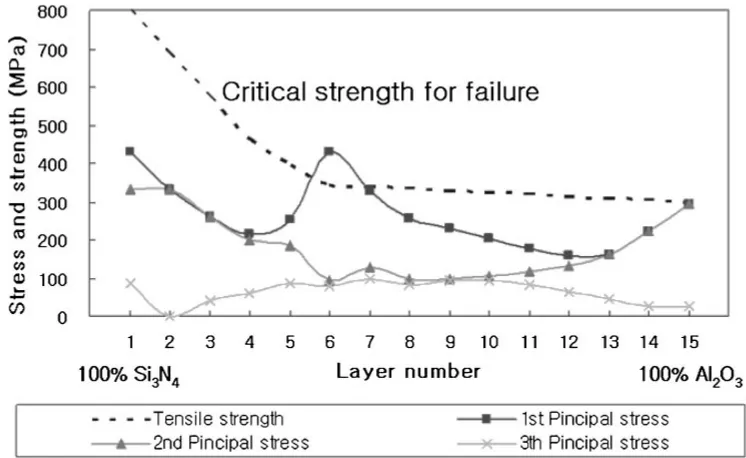
Using maximum principal stress theory, Figure 5 shows its calculated 1st, 2nd, and 3rd principal stresses to predict whether this sample with 15 functionally graded layers will have a crack or not. The calculated principal stresses are compared with the critical strength for failure. The critical strength of each layer has been calculated according to the linear rule of mixture, and critical strength for failure has been extracted from maximum component stress values for each layer as shown in Table 1. Figure 5 compares its principal stresses with critical strengths for failure within each layer. As a result, 1st principal stress exceeds critical
strength for failure around 90% 12H/10% Al2O3 area. This position seems to match with actual crack position of FGM joint as shown in Figure 2. Moreover, maximum tensile stress theory was used to predict the maximum stress point in FGM sample as shown in Fig. 6. Hoop, axial and radial stresses for this FGM sample are calculated to be compared with the critical strength for failure. In this analysis, axial stress at 90% 12H/10% Al2O3area exceeded critical strength
for failure. In other words, a region in 90% 12H/10% Al2O3 has a high axial stress of 430 MPa compared to radial and hoop stresses. Since axial stress is considerably much higher than radial and hoop stresses, this explains why the actual samples came out cracked near 90% 12H/10% Al2O3. Therefore, crack in FGM sample seems be caused by maximum axial stress in the middle of the sample around 90% 12H/10% Al2O3.
3.2 Joint microstructure
Optical micrograph of the Al2O3-Si3N4FGM joint with 15 layers is shown in Fig. 2. As shown in the Fig. 2, crack is present in the area from 90% 12H/10% Si3N4to 90% 12H/ 10% Al2O3. Thicker layers were added toward FGM between Si3N4 and 12H to relieve residual stresses since the gradient across the length of the joint was varied by 25 mass% increment in composition for FGM between Si3N4and 12H. The position of crack propagation approximately matches with the computed crack position using numerical analysis.
3.3 New composition profile of crack free joint using FEM
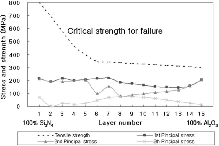
In order to obtain crack-free joint, simulation was done by varying the composition profile. According to the simulation, reduction for the weight of each layer was tried to reduce generated load by thermal expansion. As a result of simulation, generated stresses were smaller than its critical strength for failure, and the stress of each layer was almost uniform in the numerical analysis result as shown in Fig. 7 and Fig. 8. The variation of weight for each layer used for numerical analysis is shown in Table 3. Figure 7 and Figure 8 show the comparison of computed principal stresses and component stresses with its critical strength for failure of FGM joints calculated by the numerical analysis method, respectively. From those figures, residual stresses within FGM layers are below its critical strength for failure across the entire length of the sample.
Fig. 5 Comparison of computed principal stresses to its critical strength for failure of FGM joints calculated by ANSYS simulation (based on maximum principal stress theory).
[image:4.595.109.482.71.300.2]4. Conclusions
The number of layers for the FGM of Si3N4-Al2O3using polytypoid functional gradient was reduced to 15 layers of different thicknesses of layers. The finite element method was used to calculate the residual stresses in the reduced numbers of FGM sample to monitor stress distribution across the sample. Maximum principal stress and maximum tensile strength theories were used to locate maximum stress point in FGM sample. Both stress theories predicted cracked region near 90% 12H/10% Al2O3 by having its residual
stress exceeding critical stress for failure, and this estima-tion agreed well with that of fabricated sample. Therefore, it is possible to design reduced and optimized crack-free FGM layers with this numerical analysis tool. Such analyses are especially useful for graded FGM samples where the residual stresses are very difficult to measure experimen-tally. Finally, new composition profile of crack free joint was proposed based on the numerical analysis method which predicts crack-free joint with 15 layers. For future work, a sample with this composition profile need to be fabricated.
Fig. 7 Comparison of computed principal stresses with critical failure strength for new composition profile calculated by the numerical analysis method (based on maximum principal stress theory).
[image:5.595.110.482.71.297.2] [image:5.595.113.484.359.607.2]Acknowledgements
This work was supported by the Korean government (MOEHRD, Basic Research Promotion Fund (KRF-2007-311-D00516)) and Brain Korea 21 at Hanyang University in Korea. Also, this work was supported by ERC
(Micro-Thermal System Research Center) at Seoul National University in Korea. Authors would like to thank Professor Seung-Bo Sim and Professor Chul-goo Cho at Hanyang University for their support of Hot Press.
REFERENCES
1) K. Ravichandran: Mater. Sci. Eng. A.201(1995) 269–276. 2) D. Munz and Y. Y. Yang: J. Appl. Mech.59(1992) 856–861. 3) C. S. Lee, X. Zhang and G. Thomas: Acta Mater.49(2001) 3775–3780. 4) R. Watanabe, A. Kawakasi and H. Takahashi: Mechanics and Mechanisms of Damage in composites and Multi-Materials, (Mechanical Engineering publication, London, 1991) pp. 285–299. 5) M. Koizumi:Ceramic Engineer Science Proc., (1992) pp. 333–347. 6) B. H. Rabin and R. L. Williamson:Microcomposites and Nanophase
Materials, ed. by D. C. Van Aken, G. S. Was and A. K. Ghosh, (TMS-AIME, Warrendale, PA, 1991) pp. 103–113.
7) R. Watanabe and A. Kawasaki:Composite Materials, ed. by A. T. Di Benedetto, L. Nicolais and R. Watanabe, (Elsevier Science, London, 1992) pp. 197–208.
8) M. Koizumi and K. Urabe:Ceramics Today Tomorrow’s Ceramics, ed. by P. Vincenzini, (Elsevier Science, London, 1991) pp. 1939–1945. 9) B. H. Rabin, R. L. Williamson, R. J. Heaps and A. W. Erickson: Proc. 1st Int. Conf. Advanced Synthesis of Engineered Materials, (San Francisco, CA, 1992) pp. 175–180.
10) C. S. Lee, S. H. Ahn, L. C. De Jonghe and G. Thomas: Mat. Sci. Eng. A.
434(2006) 160–165.
11) C. S. Lee, S. G. Kim, S. H. Ahn, L. C. DeJonghe and G. Thomas: Mat. Trans.48(2007) 2489–2493.
12) Website,http://www.goodfellow.com/ 13) Website,http://www.ansys.com/
14) J. G. Choi and S. B. Lee:Analysis material science, (Cheong Moon Gak Publishers, Seoul, 2000) pp. 196–198.
15) B. J. Choi, Y. H. Koh and H. E. Kim: J. Am. Ceram. Soc.81(1998) 2725–2728.
16) P. L. Wang, W. Y. Sun and D. S. Yan: Mat. Sci. Eng. A.272(1999) 351–356.
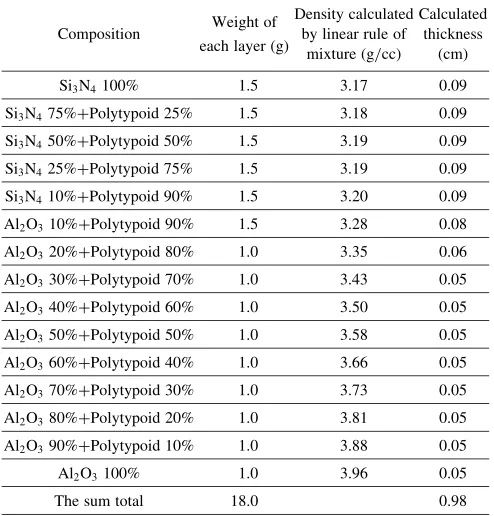
[image:6.595.112.482.71.310.2]17) Website,http://www.matweb.com(99.9% Alumina) Table 3 Weight of each layer, density calculated by linear mixture rule,
and thickness computed by the density used to design new composition profile of crack free joint in the numerical analysis.
Weight of Density calculated Calculated Composition
each layer (g) by linear rule ofmixture (g/cc) thickness(cm)
Si3N4100% 1.5 3.17 0.09
Si3N475%+Polytypoid 25% 1.5 3.18 0.09
Si3N450%+Polytypoid 50% 1.5 3.19 0.09
Si3N425%+Polytypoid 75% 1.5 3.19 0.09
Si3N410%+Polytypoid 90% 1.5 3.20 0.09
Al2O310%+Polytypoid 90% 1.5 3.28 0.08
Al2O320%+Polytypoid 80% 1.0 3.35 0.06
Al2O330%+Polytypoid 70% 1.0 3.43 0.05
Al2O340%+Polytypoid 60% 1.0 3.50 0.05
Al2O350%+Polytypoid 50% 1.0 3.58 0.05
Al2O360%+Polytypoid 40% 1.0 3.66 0.05
Al2O370%+Polytypoid 30% 1.0 3.73 0.05
Al2O380%+Polytypoid 20% 1.0 3.81 0.05
Al2O390%+Polytypoid 10% 1.0 3.88 0.05
Al2O3100% 1.0 3.96 0.05
The sum total 18.0 0.98
Fig. 8 Comparison of the computed radial, axial and hoop stresses with critical failure strength for new composition profile calculated by the numerical analysis method (Maximum tensile stress theory).
[image:6.595.46.293.396.654.2]