Rake Receiver Detection of Adaptive Modulation
Aided CDMA over Frequency Selective Channels
Byoung-Jo Choi and Lajos Hanzo
1Dept. of ECS, University of Southampton, SO17 1BJ, UK.
Tel: +44-23-8059-3125, Fax: +44-23-8059-4508
Email:lh
1@ecs.soton.ac.uk
,
http://www-mobile.ecs.soton.ac.uk
Abstract—A closed form Bit Error Ratio (BER) formula is derived for a
fixed-mode Quadrature Amplitude Modulation (QAM) scheme employing Rake receivers and receiver antenna diversity. The analysis is extended to constant power Adaptive QAM (AQAM) expressing the average BER and the average throughput as a closed form function of the modulation mode switching levels. Then, the switching levels are optimised so that the aver-age throughput is maximised, while maintaining a given target BER. This results in a constant-BER, variable-throughput arrangement. The results show that our constant-power AQAM scheme exhibits an SNR gain of about 5dB in comparison to fixed-mode QAM, when operating over a Wireless Asynchronous Transfer Mode (W-ATM) channel employing one antenna. However, the achievable throughput gain of the system over conventional fixed-mode modems is substantially reduced, as the diversity order of the receiver is increased.
I. INTRODUCTION
Mobile communications channels typically exhibit time vari-ant channel quality fluctuations [1] and hence conventional fixed-mode modems suffer from bursts of transmission errors, even if the system was designed for providing a high link margin. An efficient approach to mitigating these detrimen-tal effects is to adaptively adjust the transmission format based on the near-instantaneous channel quality perceived by the re-ceiver, which is fed back to the transmitter with the aid of a feedback channel [2]. This scheme requires a reliable feed-back link from the receiver to the transmitter and the chan-nel quality variation should be sufficiently slow for the trans-mitter to be able to adapt. Hayes [2] proposed transmission power adaptation, while Cavers [3], suggested invoking a vari-able symbol duration scheme in response to the perceived chan-nel quality at the expense of a variable bandwidth requirement. Since a variable-power scheme increases both the transmitted power requirements and the level of co-channel interference [4], instead variable-rate Adaptive Quadrature Amplitude Modula-tion (AQAM) was proposed by Steele and Webb as an alterna-tive, employing various star-QAM constellations [4]. With the advent of Pilot Symbol Assisted Modulation (PSAM) [5] Ot-suki, Sampei and Morinaga [6] employed square constellations instead of star constellations for AQAM, as a practical fading counter measure. Analysing the channel capacity of Rayleigh fading channels [7], [8], [9], Goldsmith and Varaiya showed that variable-power, variable-rate adaptive schemes are optimum,
The financial support of LGE, Korea; The CEC, Brussels and that of the EP-SRC, UK is gratefully ackowledged.
approaching the achievable channel capacity and they also char-acterised the average throughput performance of variable-power AQAM [8]. However, they also found that the additional chan-nel capacity achieved by the variable-power assisted adaptation regime over the constant-power, variable-rate scheme is a frac-tion of one decibel for most types of fading channels [10], [8].
Another approach to mitigating the effects of fading is in-volving diversity techniques, such as space, frequency or time diversity [11, Ch 5]. Receiver antenna diversity using var-ious combining methods [11, Ch 5] and transmitter antenna diversity employing space-time codes [12], [13] belong to the family of space-diversity schemes. By contrast, Rake-receiver [14] based Direct-Sequence (DS) Code Division Multi-ple Access (CDMA) [15] and Multi Carrier CDMA [16], [17], [18] can be classified as frequency-diversity assisted techniques. Since the above two approaches are independent of each other, both Rake-receiver and antenna diversity aided schemes can be combined with AQAM. Hence, the aim of this
contribu-tion is to analyse the performance of a combined frequency-and space-diversity assisted AQAM system. Here, we em-ployed constant-power AQAM, justified by the arguments of [4] regarding the transmit power requirements, since a variable-power scheme would result in increased co-channel interference. We note furthermore that the additional throughput gain due to applying a variable-power, rather than a constant-power scheme is small [10]. Based on the performance analysis of our combined AQAM system, we study the upper-bound performance of Rake receiver as-sisted AQAM employing antenna diversity.
In the next section, our system model is introduced. The Bit Error Ratio (BER) performance of Rake-receiver assisted fixed-mode QAM employing antenna diversity is analysed in Sec-tion III. In SecSec-tion IV, the average BER and the throughput of combined AQAM is expressed in a closed form as a function of the modulation switching thresholds. Finally, the performance of Rake receiver and receiver antenna diversity assisted AQAM employing optimum mode switching levels is presented in Sec-tion V, before concluding in SecSec-tion VI.
II. SYSTEMMODEL
Our Rake-receiver andD-antenna diversity assisted AQAM
low-RAKE
RAKE
RAKE
Modulator
Receiver Transmitter Channel
Mode Control M−QAM
Channel Estimation
Demodulator M−QAM
h
1 (t;)
z
1 (t)
s(t)
h
2 (t;)
z
2 (t)
h
D (t;)
z
[image:2.612.314.553.171.240.2]D (t)
Fig. 1. Equivalent low-pass model of aD-th order antenna diversity based
RAKE-receiver assisted AQAM system
passm-ary QAM signals(t); S(f) =0forjfj > 1=2W, is
transmitted over time variant frequency selective fading chan-nels and received by a set ofD RAKE-receivers. Each
Rake-receiver [14], [19] combines the resolvable multi-path compo-nents using Maximal Ratio Combining (MRC). The combined signals of the D number of Rake-receivers seen in Fig. 1 are
summed and demodulated using the estimated channel qual-ity information. The estimated signal-to-noise ratio (SNR) ^
is fed back to the transmitter and it is used for deciding upon the highest throughputm-ary square QAM modulation mode
capable of maintaining the target BER. A K-mode adaptive
modulation scheme adjust its transmit mode to mode-k, where
k 2 f0; 1K 1g, by employingm
k-ary modulation
ac-cording to the estimated SNR^perceived at the receiver. The
mode selection rule is given by:
Choose modek, when s k
^ < s
k +1
; (1)
where a switching levels
k belongs to the set
s = fs
k jk =
0;1;;Kg. The boundary switching levels are usually given
ass 0
=0ands K
=1. The Bit Per Symbol (BPS) throughput
b
kof a modulation mode
kis given asb k
=log
2 (m
k )ifm
k 6=0,
otherwiseb k
=0. It is convenient to define the incremental BPS
c
k as c
k =b
k b
k 1, when
k >0and asc 0
= b
0, provided
thatk = 0. In an effort to derive the achievable upper bound
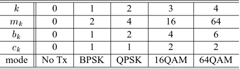
performance we assume that the channel quality is estimated perfectly and it is available at the transmitter immediately. The effects of channel estimation error and feedback delay on the performance of AQAM were studied for example in [10]. Here a 5-mode square-constellation based AQAM scheme has been studied due to the superior BER performance of Gray-mapped square QAM constellations in comparison to otherm-ary
tech-niques [21]. The parameters of this 5-mode AQAM system are summarised in TABLE I.
The low-pass equivalent impulse response of the channel be-tween the transmitter and thed-th antenna,d=1;2;;D, may
be represented as [19]:
h
d (t;)=
N
X
n=1 h
d;n (t)Æ
n
W
; (2)
where fh d;n
(t)g is a set of independent complex valued
sta-tionary random processes. The maximum number of resolvable
multi-path componentsN is given bybT m
Wc+1, whereT m
is the multi-path delay spread of the channel [19]. Hence, the low-pass equivalent received signal r
d
(t)at the d-th antenna,
d=1;2;;D, can be represented as:
r
d (t)=
N
X
n=1 h
d;n (t)s
t n
W
+z
d
(t); (3)
wherez d
(t)is a zero mean Gaussian random process having a
two-sided power spectral density ofN o
=2. Let us assume that
TABLE I
THE PARAMETERS OF5-MODEAQAMSYSTEM
k 0 1 2 3 4
m
k 0 2 4 16 64
b
k 0 1 2 4 6
c
k 0 1 1 2 2
mode No Tx BPSK QPSK 16QAM 64QAM
the fading is sufficiently slow or(t) c
T, where (t) c is
the channel’s coherence time [1] andT is the signaling period.
Then, h d;n
(t) over a signaling period T can be simplified to
h
d;n
(t) =
d;n e
jd;n
, where the fading magnitude
d;n is
as-sumed to be Rayleigh distributed and the phase
d;nis assumed
to be uniformly distributed.
III. BER ANALYSIS OFm-ARYQAM
An ideal RAKE receiver [14] combines all the signal powers scattered overN paths in an optimal manner so that the
instan-taneous Signal-to-Noise Ratio (SNR) per symbol at the RAKE receiver’s output can be maximised [19]. The noise at the RAKE receiver’s output is known to be Gaussian [19]. The SNR,
d, at
thed-th ideal RAKE receiver’s output in Fig. 1 is given as [19]:
d =
N
X
n=1
d;n
; (4)
where d;n
= E=N
o
2
d;n
andf d;n
g is assumed to be
nor-malised, such that
P
N
n=1
2
d;n
becomes unity. Since we as-sumed that each multi-path component has an independent Ray-leigh distribution, the characteristic function of
dcan be
repre-sented as [19, pp 802]:
d (j)=
N
Y
n=1 1
1 j
d;n
; (5)
where d;n
=E=N
o E[
2
d;n
]. Let us assume further more that
each of theDdiversity channels of Fig. 1 has the same
multi-path intensity profile (MIP), although in practical systems it may have a different MIP. Under this assumption,
d;nin (5) can be
written as
n. The total SNR per symbol,
, at the output of the
demodulator depicted in Fig. 1 is given as:
= D
X
d=1
d
while the characteristic function of, under the assumption of
independent identical diversity channels, can be formulated as:
(j)= N Y n=1 1 (1 j n ) D : (7)
Applying the well-known technique of Partial Fraction Ex-pansion (PFE) [20],
(j)can be expressed as:
(j)= D X d=1 N X n=1 d;n 1 (1 j n ) d ; (8)
where the constant
d;ncan be found by equating (7) and (8).
The PDF of,f
(), can be found by applying the inverse
Fourier transform to
(j)in (8), which is given, with the aid
of [19, pp 781 (14-4-13)], by:
f()= D X d=1 N X n=1 d;n 1 (d 1)! d n d 1 e =n : (9)
Since we now have the PDFf
()of the channel SNR, let
us calculate the average BER ofm-ary square QAM employing
Gray mapping. The average BERP
ecan be expressed as [21],
[19]: P e;k = Z 1 0 p m k
()f()d; (10)
wherep mk
() is the BER of m-ary square QAM employing
Gray mapping over Gaussian channels [21]:
p mk ()= X i A i Q( p a i
); (11)
where Q(x) is the Gaussian Q-function defined as Q(x) ,
1 p 2 R 1 x e t 2 =2
dtandfA i
;a
i
gis a set of modulation mode
de-pendent constants, which are given, for example, in [21], [22]. The average BER ofm-ary QAM in our scenario can be
calcu-lated by substitutingp m
k
()of (11) andf
()of (9) into (10):
P e;k ()= Z 1 0 X i A i Q( p a i
)f()d (12)
= X i A i P e (;a
i
); (13)
where each constituent BERP e
(;a
i
)is defined as:
P
e (;a
i )= Z 1 0 Q( p a i
)f()d: (14)
Using the similarity off
()in (9) and the PDF of the SNR of a
Dantenna-diversity assisted Maximal Ratio Combining (MRC)
system transmitting over flat Rayleigh channels [19, pp 781], the closed form solution for the component BERP
e (;a
i )can
be expressed as:
P
e (;a
i ) = D X d=1 N X n=1 1 p 2 Z 1 0 Z 1 p 2 e x 2 =2 d;n d 1 e =n (d 1)! d n dxd = D X d=1 N X n=1 d;n 1 n 2 d d 1 X i=0 d 1+i i 1 2 (1+ n ) i ; (15) where n , q ain 2+a i n
and the average SNR per symbol is
=D P N n=1
n . Substituting P
e (;a
i
)of (15) into (13), the
average BER of anm-ary QAM Rake receiver using antenna
diversity can be expressed in a closed form.
IV. PERFORMANCE OFAQAM
In this section, we consider an ideal five-mode AQAM scheme characterised by the parameters given in TABLE I.
A. Average Throughput
The average throughputB(;s) expressed in terms of Bits
Per Symbol (BPS) is given by [23]:
B(;s)= K 1 X k =0 b k Z sk +1 s k
f()d= K 1 X k =0 c k F c
(); (16)
where F c
() is the complementary Cumulative Distribution
Function (CDF) of the instantaneous SNR, given as:
F c ()= D X d=1 N X n=1 d;n e =n d 1 X k =0 (= n ) k
(k+1)
; (17)
where (x)is the Gamma function [20].
B. Average Bit Error Ratio
Let us define the mode-specific average BERP kas: P k , Z s k +1 s k p mk
()f()d: (18)
Upon substitutingp m
k
()of (11) andf()of (9) into (18), we
have: P k = X i A i D X d=1 N X n=1 d;n Z s k +1 s k Q( p a i ) d 1 e = n (d 1)! d n d = X i A i D X d=1 N X n=1 d;n P R (s k ;s k +1 ; n ;d;a
i
): (19)
A closed form expression for P R (s k ;s k +1 ; n ;d;a
i
) can be
found by applying change-of-variables repeatedly, which can be expressed as: P R = 2 4 e = n Q( p a i ) d 1 X j=0 (= n ) j
where[g()] s
k +1
s
k
,g(s
k +1 ) g(s
k )andX
jis given by:
X
j (;
n ;a
i )=
2
n
p
2a
i
(j+ 1
2 )
j
n
(j+1) j
X
k =1
2 2
n
a
i
j k
k
1
2
(k+ 1
2 )
e a
i =(2
2
n )
+
2 2
n
a
i
n
j
1
p
(j+
1
2 )
(j+1)
n Q(
p
a
i =
n
) ; (21)
where, again, n
, q
a
i
n
2+ain
and (x)is the Gamma function.
Then, the average BERP avg
(;s)of our adaptive modulation
scheme can be represented as [23] :
P
avg
(;s)= 1
B(;s) K 1
X
k =0 b
k P
k
; (22)
where the average BPS throughputB()and the mode-specific
average BERP
kare given by (16) and (19), respectively, and b
k
is the BPS form
k-ary fixed-mode modulation scheme.
C. Optimum switching levels
Torrance and Hanzo [24] proposed a set of mode switch-ing levels s optimised for achieving the highest average BPS
throughput while maintaining the target average BER. The au-thors of this contribution recently proposed a set of SNR-dependent mode switching levels [25], which keeps the aver-age BER of AQAM constant, while maximising the achievable throughput. The sets of switching levels derived in [24], [25] are based on Powell’s multidimensional optimisation technique [26] and hence the optimisation process may become trapped in a lo-cal minimum. In order to overcome this problem, we derived an optimum set of switching levels [27] employing the Lagrangian multiplier technique and showed that this set of switching levels results in the global optimum in a sense that the correspond-ing AQAM scheme obtains the maximum possible average BPS throughput, while maintaining the target average BER. In this paper we employ the globally optimised switching levels of [27] for studying the performance of the proposed Rake receiver aided andD-antenna diversity assisted AQAM scheme.
V. RESULTS ANDDISCUSSIONS
The associated performance results of the AQAM system are shown in Fig. 2 for transmission over the 3-path indoor W-ATM channel model of [21, pp. 476] employing a single antenna . Specifically, the W-ATM channel is a 3-path indoor channel, where the average SNR for each path is given as
1
=0:79192,
2
= 0:12424 and 3
= 0:08384. The performance
de-picted in Fig. 2 corresponds to the single user performance of a Rake-receiver assisted DS-CDMA system employing AQAM,
i.e. without inflicting multi-user interference. Near single user
performance is achievable for multiple users, when we employ an optimal multi-user detector [28]. The BER of fixed mode modems communicating over this channel were comparable to that recorded for transmission over flat Rayleigh channels us-ing second-order antenna diversity. Fig. 2(a) and 2(b) show that
0 5 10 15 20 25 30 35 40 Average Channel SNR (dB) 10-7
10-6 10-5 10-4 10-3 10-2 10-1 100
BER
64-QAM 16-QAM QPSK BPSK
D =1
Pth=10
-2
Pth=10
-3
Pth=10
-4
Pth=10
-5
(a) BER
0 5 10 15 20 25 30 35 40 Average Channel SNR (dB) 0
1 2 3 4 5 6 7
Throughput
(BPS)
5-mode
4-mode
3-mode
2-mode
Pt=10
-3
D =1
BPSK QPSK
16-QAM 64-QAM
[image:4.612.307.559.18.163.2](b) Throughput:Pt=10 3
Fig. 2. BER and throughput performance for transmission over the Wireless ATM channel [21] (N=3) using a single antenna, i.e.D=1.
1 2 3 4 5 6 Number of Antenna,D
0 5 10 15 20 25 30 35
A
verage
Channel
SNR
(dB)
4 BPS 2 BPS 1 BPS Adaptive Fixed
Pt=10
-3
(a) SNR versus diversity order
1 2 3 4 5 6 Number of Antenna,D
1 2 3 4 5 6 7 8
Throughput
(BPS)
SNR for 4 BPS (F) SNR for 2 BPS (F) SNR for 1 BPS (F) Adaptive Fixed
Pth=10
-3
(b) Throughput versus diversity order
Fig. 3. The required SNR and the achievable BPS throughput of AQAM using different orders of antenna diversity for transmission over the Wireless ATM channel [21] (N=3) at a target BER ofP
th =10
3
the system maintained the required constant target BER, while increasing the average throughput, as the SNR increased.
The performance of the Rake receiver assisted AQAM scheme is shown in Fig. 3 for various antenna diversity or-ders together with the performance of the constituent fixed mode modems employing Rake-receivers. The SNR gain of the AQAM scheme over the fixed modems was in the range of 4dB to 5dB, when a single antenna was used. When the num-ber of antennas employed was higher than two, this gain was reduced below 1dB compared to the fixed mode QPSK and 16-QAM modems employing Rake-receivers. Fig. 3(b) shows the throughput of the Rake-receiver assisted AQAM system at the specific SNRs, where the fixed mode modems employing Rake-receivers achieved the target BER of10
3
. As seen by com-paring Fig. 2(b) and Fig. 3(b), the AQAM system achieved a throughput of2:2BPS at the SNR of13:2dB, where a BPSK
modem had a throughput of 1 BPS, provided that a single an-tenna was employed. As seen in Fig. 3(b) the throughput gains of the AQAM system eroded, as the diversity order was in-creased.
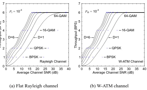
[image:4.612.310.556.218.379.2]0 5 10 15 20 25 30 35 40 Average Channel SNR (dB) 0
1 2 3 4 5 6 7
Throughput
(BPS)
Pt=10
-3
BPSK QPSK
16-QAM 64-QAM
D=1 D=6
Rayleigh Channel
(a) Flat Rayleigh channel
0 5 10 15 20 25 30 35 40 Average Channel SNR (dB) 0
1 2 3 4 5 6 7
Throughput
(BPS)
Pth=10
-3
BPSK QPSK
16-QAM 64-QAM
D=1 D=6
W-ATM Channel
[image:5.612.48.294.14.165.2](b) W-ATM channel
Fig. 4. BPS throughput of 5-mode AQAM (P th
=10 3
). Markers represent the throughput of fixed modems. As expected, the right most markers and lines represent the single antenna (D=1) scenario.
modems can be observed also in Fig. 4. The markers in the fig-ure represent the throughput of fixed mode modems. We can observe that the markers approach the corresponding AQAM-related lines in both graphs, as the order of antenna diversity (D) is increased. The distance between the markers and lines
was already shown in in Fig. 3(a). The effects of discrete-rate modulation can also be observed in Fig. 4. The second deriva-tives of the graphs are not monotonic. This became pronounced for the larger values of D, where the switching between
con-stituent modulation modes results in the undulation observed in the BPS curve. This suggests that despite the optimised mod-ulation switching levels, the sub-optimal effects of using only five different discrete transmission rates could not be completely eliminated.
VI. CONCLUSIONS
The BER of AQAM systems employing Rake-receivers and antenna diversity, was analysed and a closed form BER ex-pression was derived. The average BER and the throughput of a constant-power AQAM system employing Rake-receivers and antenna diversity were expressed in closed forms. This fa-cilitated the optimisation of modulation switching levels. The optimised AQAM system exhibited a constant BER and an in-creased throughput comparable to variable-rate, variable-power MQAM systems [10]. We found that the SNR gain of AQAM modems erodes, as the order of diversity increases.
REFERENCES
[1] R. Steele and L. Hanzo, Eds., Mobile Radio Communications, IEEE Press - John Wiley & Sons, New York, USA, 2nd edition, 1999.
[2] J. F. Hayes, “Adaptive feedback communications,” IEEE Transactions on
Communications, vol. 16, no. 1, pp. 29–34, 1968.
[3] J. K. Cavers, “Variable rate transmission for rayleigh fading channels,”
IEEE Transactions on Communications, vol. 20, pp. 15–22, February
1972.
[4] W. T. Webb and R. Steele, “Variable rate QAM for mobile radio,” IEEE
Transactions on Communications, vol. 43, no. 7, pp. 2223–2230, 1995.
[5] M. L. Moher and J. H. Lodge, “TCMP—a modulation and coding strategy for rician fading channels,” IEEE Journal on Selected Areas in
Communi-cations, vol. 7, no. 9, pp. 1347–1355, December 1989.
[6] S. Otsuki, S. Sampei, and N. Morinaga, “Square QAM adaptive
modula-tion/TDMA/TDD systems using modulation level estimation with Walsh function,” Electronics Letters, vol. 31, no. 3, pp. 169–171, February 1995. [7] W. C. Y. Lee, “Estimate of channel capacity in Rayleigh fading environ-ment,” IEEE Transactions on Vehicular Technology, vol. 39, no. 3, pp. 187–189, August 1990.
[8] A. J. Goldsmith and P. P. Varaiya, “Capacity of fading channels with chan-nel side information,” IEEE Transactions on Information Theory, vol. 43, no. 6, pp. 1986–1992, November 1997.
[9] M. S. Alouini and A. J. Goldsmith, “Capacity of Rayleigh fading channels under different adaptive transmission and diversity-combining technique,”
IEEE Transactions on Vehicular Technology, vol. 48, no. 4, pp. 1165–
1181, July 1999.
[10] A. Goldsmith and S. Chua, “Variable rate variable power MQAM for fading channels,” IEEE Transactions on Communications, vol. 45, pp. 1218–1230, October 1997.
[11] W. C. Jakes Jr., Ed., Microwave Mobile Communications, John Wiley & Sons, New York, USA, 1974.
[12] V. Tarokh, N. Seshadri, and A. Calderbank, “Space-time codes for high data rate wireless communication: Performance criterion and code con-struction,” IEEE Transactions on Information Theory, vol. 44, no. 2, pp. 744–765, March 1998.
[13] S. M. Alamouti, “A simple transmit diversity technique for wireless com-munications,” IEEE Journal on Selected Areas in Communications, vol. 16, no. 8, pp. 1451–1458, October 1998.
[14] R. Price and E. P. Green Jr., “A communication technique for multipath channels,” Proceedings of the IRE, vol. 46, pp. 555–570, March 1958. [15] R. L. Pickholtz, L. B. Milstein, and D. L. Schilling, “Spread spectrum for
mobile communications,” IEEE Transactions on Vehicular Technology, vol. 40, no. 2, pp. 312–322, May 1991.
[16] N. Yee, J-P. Linnartz, and G. Fettweis, “Multicarrier CDMA in indoor wireless radio networks,” in Proceedings of IEEE PIMRC 1993, 1993, pp. 109–113.
[17] K. Fazel and L. Papke, “On the performance of convolutionally-coded CDMA/OFDM for mobile communication system,” in Proceedings of
IEEE PIMRC 1993, 1993, pp. 468–472.
[18] A. Chouly, A. Brajal, and S. Jourdan, “Orthogonal multicarrier techniques applied to direct sequence spread spectrum CDMA systems,” in
Proceed-ings of IEEE GLOBECOM 1993, Houston, USA, 29 November – 2
De-cember 1993, pp. 1723–1728.
[19] J. G. Proakis, Digital Communications, Mc-Graw Hill International Edi-tions, 3rd edition, 1995.
[20] E. Kreyszig, Advanced engineering mathematics, John Wiley & Sons, Inc., 7th edition, 1993.
[21] L. Hanzo, W. T. Webb, and T. Keller, Single- and Multi-carrier
Quadra-ture Amplitude Modulation, IEEE Press-John Wiley, New York, USA,
April 2000.
[22] D. Yoon, K. Cho, and J. Lee, “Bit error probability of M-ary Quadrature Amplitude Modulation,” in Proceedings of IEEE VTC 2000 Fall. IEEE, September 2000, vol. 5, pp. 2422–2427.
[23] J. M. Torrance and L. Hanzo, “Upper bound performance of adaptive modulation in a slow Rayleigh fading channel,” Electronics Letters, vol. 32, no. 8, pp. 718–719, 11 April 1996.
[24] J. M. Torrance and L. Hanzo, “Optimisation of switching levels for adap-tive modulation in a slow Rayleigh fading channel,” Electronics Letters, vol. 32, no. 13, pp. 1167–1169, 20 June 1996.
[25] B. J. Choi, M. M ¨unster, L. L. Yang, and L. Hanzo, “Performance of Rake receiver assisted adaptive-modulation based CDMA over frequency selec-tive slow Rayleigh fading channel,” Electronics Letters, vol. 37, no. 4, pp. 247–249, February 2001.
[26] W. H. Press, S. A. Teukolsky, W. T. Vetterling, and B. P. Flannery,
Numer-ical Recipies in C, Cambridge University Press, 1992.
[27] B. J. Choi and L. Hanzo, “Optimum mode-switching levels for adaptive modulation systems,” unpublished, 2001.
![Fig. 2.ATM channel [21] (](https://thumb-us.123doks.com/thumbv2/123dok_us/1031044.618490/4.612.310.556.218.379/fig-atm-channel.webp)