Abstract—Transportation of objects by groups of mobile robots can be advantageous when an object is too large or heavy to be effectively manipulated by a single robot on its own. This article proposes combining the cluster space control methodology with explicit force control to effectively and safely move such an object with mobile robots. Cluster space control is used to maintain the formation of the mobile robots and their position relative to the object. The explicit force control allows the safe application of desired forces and torques on the object to be moved and treats the robots as separate actuators, as opposed to combining them with the object into a single plant. In this paper the proposed control architecture and initial experimental results from a hardware testbed are presented.
Index Terms—cluster space control, cooperative robotics, force control, mobile robot actuators, object transportation
I. INTRODUCTION
OBOTIC systems have become entrenched in manufacturing, remote exploration, and other areas that require dirty, dangerous, or dull tasks. While robots have been created for a wide variety of situations, sometimes a single robot is unable to accomplish desired tasks independently without becoming prohibitively large and expensive. In some situations where a solitary robot may give an unsatisfactory performance, groups of robots working collaboratively can provide benefit through increasing coverage, improving redundancy, and fusing information to create improved data products [1].
One application that is being researched for multi-robot systems is object transportation. While there has been research into transportation in a wide variety of
Manuscript received July 21, 2014; revised August 11, 2014. Elements of this work, to include control system development, creation of the experimental testbed, field experimentation, etc. have been sponsored, in part, by the SCU Robotic Systems Laboratory, the SCU School of Engineering, the SCU Technology Steering Committee; and through funds from National Science Foundation Grant No. CNS-0619940. Any opinions, findings, conclusions or recommendations expressed in this material are those of the authors and do not necessarily reflect the views of the National Science Foundation or Santa Clara University.
M. A. Neumann is with the Robotic Systems Lab, Santa Clara University, Santa Clara CA 95053, USA (phone: 408-551-6047; e-mail: [email protected]).
M. H. Chin is with the Robotic Systems Lab, Santa Clara University, Santa Clara CA 95053, USA (e-mail: [email protected]).
C. A. Kitts is with the Robotic Systems Lab, Santa Clara University, Santa Clara CA 95053, USA (e-mail: [email protected]).
applications, including via quadrotors [2], [3], tugboats [4], [5], and robotic fish [6], the bulk of the research has been performed using terrestrial vehicles. Much of the research into land-based transport has focused on mobile manipulators [7]-[9].
For transportation approaches where the mobile robots move the object through contact with the bodies of the robots themselves, strategies can be divided into the three categories: 1) form closure, where robots surround the object providing contact forces that can constrain the motion in any direction; 2) conditional closure, which is similar to form closure though the constraint on motion in one or more directions is provided by external forces (like friction or gravity) instead of robots; and 3) object closure, or caging, where the object is surrounded by robots that may not be touching the object itself but are close enough to one another that the object cannot slip through [10]. Although these strategies have been defined in terms of force constraints on the object, in practice they are typically implemented kinematically, without explicitly measuring and controlling the forces.
Some initial research in the area focused on asynchronous collaboration where each robot alternates between pushing and waiting for the other robot(s) to act [11], [12] or allocating the tasks of moving forward and rotating to different robots [13]. Simultaneous action by multiple robots has been explored using a number of different multi-robot control architectures including leader-follower [14], swarm robotics [15], potential fields [16], and cluster control [17].
Whereas form closure, conditional closure, and object closure are a perfectly reasonable way to transport objects, their implementation using kinematic controllers is often less than optimal. If the object is too heavy or becomes stuck a kinematic controller may create forces large enough to damage the object or one of the robots. Furthermore, from a control law design perspective, the object to be transported is treated as a disturbance rather than as an object to be controlled. Instead, it would be preferable to actively measure the interaction between the robots and the transported object while there is contact. Some researchers have incorporated force sensing into object transportation, though primarily on mobile robots equipped with manipulators [18] and, to a lesser extent, mobile robots without the ability to grasp the object [19].
We propose performing a box-pushing maneuver by
Object Manipulation through Explicit Force
Control Using Cooperative Mobile Multi-Robot
Systems
Michael A. Neumann, Matthew H. Chin, and Christopher A. Kitts
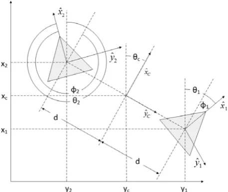
Fig. 1 A formation composed of two mobile robots can be defined by traditional robot space variables x1, y1, θ1, x2, y2, θ2, which describe the
position of each mobile robot with respect to a global frame. Another way to define a group of robots utilizes cluster space variables to define the location, orientation, and shape of the formation. One possible set of cluster space variables for a two robot formation, which is shown in this figure, is xC, yC, θC, d, φ1, φ2.
applying explicitly controlled forces using a cluster-controlled formation of mobile robots. In this architecture, cluster control is used to position the mobile robots relative to the box while the forces applied by each robot are controlled to achieve a desired resultant force and torque on the object. Use of this method has several distinct characteristics: 1) the object to be transported is formally defined as the plant, independent of the robotic system, 2) the mobile robots are treated as a single virtual actuator that applies forces and torques to control object motion, 3) forces are constantly being measured making it easy to disengage if they become dangerously high, 4) simultaneous action by all robots provides a quicker response than turn-based approaches, and 5) cluster control is capable of providing the spatial control between the robots and the box, thereby ensuring stable pushing and efficient torque application.
II. CLUSTER CONTROL REVIEW
Cluster space control is a control architecture where a
formation of mobile robots is specified by its aggregate position, orientation and shape; variables describing these pose parameters, and their derivatives, are referred to as cluster space variables. This abstraction lets the user think in terms of the location and geometry of the formation itself instead of the position and orientation of each individual robot [20]. Fig. 1 shows a formation of two mobile robots with a conventional “robot space” description of their individual positions, where the vector of robot position variables is:
(
1, 1, 1, 2, 2, 2)
.R= x y θ x y θ (1)
In contrast, the same formation can also be described using the cluster space approach. In Fig. 1 a cluster frame, {C}, is located at the midpoint and oriented with yˆC pointed towards robot 1. The size of the cluster is denoted by d, the distance between {C} and a robot. Individual robot orientations are relative to {C} and are described by φ1 and
φ2. Accordingly, the cluster pose vector is:
(
C, C, C, d, 1, 2)
C= x y θ ϕ ϕ . (2)
Kinematic equations transform robot space variables to cluster space variables and the inverse kinematic equations return cluster space variables to robot space variables. Taking the partial derivatives of the forward and inverse kinematic equations produces a Jacobian matrix and its inverse, which transform robot space velocities to and from cluster space velocities.
In the traditional kinematic cluster control architecture, illustrated in Fig. 2, the desired and measured state of the formation in cluster space are fed into a controller that creates cluster space command velocities. The inverse Jacobian translates the cluster space command velocities to robot space command velocities such as forward and rotational velocities. Similarly, a dynamic controller, in which control forces and torques are computed, can be composed by using the Jacobian transpose instead of the inverse Jacobian.
Fig. 3 The proposed control architecture utilizes the traditional cluster control architecture to maintain the position of the robots relative to the box. A line controller calculates a desired torque based on the distance the box lies from a desired path. This torque, a constant desired forward force, and the positions of the robots are used to calculate the desired application force for each robot. A force controller uses the desired and measured forces to determine forward velocity commands to send to the robots.
Cluster control has been successfully utilized to control formations of mobile robots on the ground, on and in water, and in air. Cluster control has also been used for applications such as dynamic guarding of marine objects [21] and gradient-based navigation [22].
III. OBJECT CONTROL APPROACH
To demonstrate our approach, we have created a path-following controller that moves a long box along a defined line. The mobile robot cluster is treated as an explicit actuator, providing forces to move the object forward and restoring torques if the object deviates from the prescribed path. While doing this, the relative position of the robots is maintained with respect to the box and to each other through the cluster control framework. Fig. 3 illustrates the proposed control architecture.
The cluster space controller sends rotational commands to the mobile robots to maintain their separation and ensure that they stay roughly centered on the box. This is achieved by using a proportional controller in the standard kinematic cluster control architecture described in the previous section. However, only the rotational commands, which control the positions of the robots along the edge of the box, are passed to the robots.
The interaction with the object is governed by a force controller similar to the architecture described in [23]. The cross track error (the perpendicular distance between the path and the center of the box), eCT, is multiplied by a
proportional gain, kCT, to determine a corrective turn angle,
ψ (which is limited to +/- 90°).
CT CT
k e
ψ = (3)
The corrective turn angle is subtracted from the bearing of the desired path, φ, giving the desired heading of the box,
θD.
D
θ = −ϕ ψ (4)
The difference between the measured heading, θ, and the desired heading is multiplied by another proportional gain,
kH, resulting in the desired torque, T, to apply on the box.
( D ) H
T = θ −θ k (5)
This torque, the position of the robots, and a desired constant forward net force on the box are utilized to determine the desired application forces for each robot. The force controller has inputs of the desired and measured application forces and outputs a linear velocity command for each robot, using a resolved rate control approach given the speed control interface for the robots.
IV. TESTBED
Verification of the control approach leveraged an existing testbed previously used for cluster control research [24].
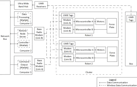
[image:3.595.350.499.579.736.2]Fig. 5 Component block diagram showing the two communication paths in the testbed.
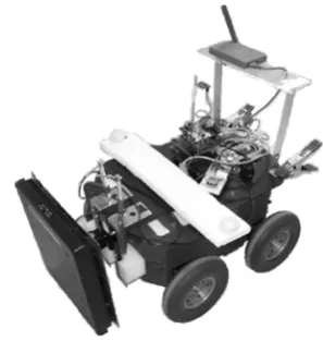
The mobile robots used were Pioneer ATTM robots equipped with packet modems to provide wireless communication with a control station. For these experiments a subsystem consisting of a hinged force sensor, Arduino microcontroller, and X-Bee radio was added to each robot to measure contact forces and separately relay the data to the controller. Fig. 4 shows a mobile robot with the added force sensors and communication systems.
In order to measure position and orientation, ultra-wide band tags were placed on both robots as well as the box. Force data from force sensing subsystems and position data from the ultra-wide band system were routed by the DataTurbine streaming data server, which the Matlab controller polled while going through its computations. The resulting commands from Matlab were routed back through the DataTurbine and packet modem system as velocity commands to each individual robot. The diagram in Fig. 5 illustrates the different components in the system.
V. RESULTS
Initial tests to demonstrate the effectiveness of the control architecture focused on pushing a box along a line. Fig. 6 shows the overhead view of the path of a box that starts at approximately (3.5,-7.5) and then moves in the negative ˆx
direction. The mobile robot actuators force the box to the desired line y = -5 with a small amount of overshoot.
[image:4.595.312.528.386.556.2]The position of the robots relative to the object is adequately controlled. The cluster space variable, d, is shown in Fig. 7 to oscillate around the desired value of the 0.8 m with an RMS error value of 0.0558 m. The lateral distance between the center of the robot formation and the midpoint of the side of the box is similarly controlled, as
Fig 6 The control system forces a box that is given an initial displacement to follow a line.
[image:4.595.310.531.590.758.2]Fig. 8 The error between the center of the cluster and the midpoint of the side of the box.
Fig. 9 The net force applied to the box by the two robots was noisy, but approximated the desired value.
Fig. 10 The measured torque during the maneuver, filtered in this figure, varies significantly more than the desired values. However, it generally follows the trend of decreasing torque as the box moves closer to the desired path.
seen in Fig. 8, with an RMS error value of 0.1186 m. Both these results are relatively good given the sensing system gives measurements that can be approximated as normally distributed with a variance of 4 cm [25].
The force control subsection of the controller also worked, though its performance was not as good as the
position controller. The net force applied to the box, seen in Fig. 9, shows significant variation. Similarly, the applied torque in Fig. 10 varies quite a bit as well. These variances are due in large part to the shortcomings of the testbed. Part of the noise is due to the sensor itself, but some of the noise is also due to overcoming Coulomb friction and attempting to control the dynamic forces on a kinematic system. Since the forces due to acceleration were negligible and there is little to no viscous friction in the system, the interaction forces when in motion were predominantly due to the contact friction with the ground and did not vary significantly. Desired forces less than the frictional force led to an effect similar to PWM; the interaction force alternated between two discrete levels with the length of time spent at each level varying such that the average approximated the desired value.
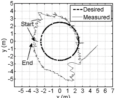
As an additional test the input to the controller was varied to attempt to push the object along a circular path of radius 2.5 m. At any moment the desired line was defined be the tangent to the circular path that lied closest to the box.
[image:5.595.321.520.454.623.2]Fig. 11 displays the overhead view of the desired and measured path of the object. The two robots were able to control the position of the object to move roughly in a circular path. It is clear that the position data is a bit noisy, particularly in the x-axis. There are also two noticeably large jumps near (5,-0.5) and (-4, 3) that are presumed to be due to sensor error. The crosstrack error is almost always positive as the box is pushed around the circle, which makes intuitive sense as a proportional controller was used and the desired line was changing over time creating a ramp input to the system.
Fig. 11 The overhead view of a box’s path when commanded to follow a circle.
VI. DISCUSSION
[image:5.595.51.277.489.661.2]Third, by monitoring forces during motion the architecture prevents hazardous forces that could be developed with standard caging methods.
In addition to the benefits there are several drawbacks to the proposed control architecture. The architecture is not ideal for kinematically controlled robots, like those used in the testbed, since there won’t be a one-to-one correspondence between velocities and forces. Furthermore, for situations with Coulomb friction forces that are significantly larger than forces due to acceleration, the robots can only effectively apply a single force (as opposed to a range of forces) while in motion. Despite these deficiencies, the architecture managed to successfully achieve the objectives in the experiments and holds promise for dynamic situations such as marine environments.
VII. SUMMARY
A novel control architecture for object manipulation by mobile robots combining cluster space control to maintain formation and explicit force control of the object was presented in this paper. The proposed architecture was shown to be capable of transporting an object. Given the initial success, work will continue with: 1) tuning of control law gains, 2) adding the ability to dynamically control the desired locations of the robots relative to the box to improve the ability to turn, 3) implementing the controller on another testbed that has better dynamics (e.g. not being dominated by a large constant sliding friction), and 4) adapting the framework so that it mirrors the hybrid force-position controllers used on robotic manipulators.
ACKNOWLEDGMENT
The authors thank Jackson Arcade for his assistance in developing the force sensing system, Mike Vlahos for helping with code, and Nick Xydes for his aid during experimentation.
REFERENCES
[1] C. A. Kitts and M. B. Egerstedt, “Design, control, and applications of real-world multirobot systems [from the guest editors],” Robotics & Automation Magazine, IEEE, vol. 15, no. 1, p. 8, Mar. 2008. [2] N. Michael, J. Fink, and V. Kumar. (2010, September). Cooperative
manipulation and transportation with aerial robots. Autonomous Robots [Online]. 30(1), pp. 73-86. Available:
http://link.springer.com/article/10.1007/s10514-010-9205-0/fulltext.html
[3] D. Mellinger, M. Shomin, N. Michael, V. Kumar, “Cooperative grasping and transport using multiple quadrotors,” in Proc. Distributed Autonomous Robotic Systems, Lusanne, 2010, pp 545-558.
[4] J. M. Esposito, M. G. Feemster, and E. Smith, “Cooperative manipulation on the water using a swarm of autonomous tugboats,” in Proc. 2008 IEEE Int. Conf. on Robotics and Automation, pp. 1501-1506.
[5] M. G. Feemster and J. M. Esposito, “Comprehensive framework for tracking control and thrust allocation for a highly overactuated autonomous surface vessel,” Journal of Field Robotics, vol. 28, no. 1, pp. 80-100, Jan./Feb. 2011.
[6] Y. Hu, L. Wang, J. Liang, T. Wang, “Cooperative box-pushing with multiple autonomous robotic fish in underwater environment,” IET Control Theory & Applications, vol. 5, no. 17, pp. 2015-2022, Nov. 2011.
[7] O. Khatib, K. Yokoi, K. Chang, D. C. Ruspini, R. Holmberg, and A. Casal, “Vehicle/arm coordination and multiple mobile manipulator
decentralized cooperation,” in Proc. 1996 IEEE/RSJ Int. Conf. on Intelligent Robots and Systems, pp. 546-553.
[8] T. Sugar and V. Kumar, “Multiple cooperating mobile manipulators,” in Proc. 1999 IEEE Int. Conf. on Robotics and Automation, vol. 2, pp. 1538-1543.
[9] C. P. Tang, R. M. Bhatt, M. Abou-Samah, and V. Krovi, “Screw-theoretic analysis framework for cooperative payload transport by mobile manipulator collectives,” IEEE/ASME Trans. Mechatronics, vol. 11, no. 2, pp. 169-178, Apr. 2006.
[10] G. A. S. Pereira, M. F. M Campos, and V. Kumar, “Decentralized algorithms for multi-robot manipulation via caging,” The Int. Journal of Robotics Research, vol. 23, no. 7-8, pp. 783-795, Aug. 2004. [11] M. J. Mataric, M. Nilsson, and K. T. Simsarin, “Cooperative
multi-robot box-pushing,” in Proc. 1995 IEEE/RSJ Int. Conf. on Intelligent Robots and Systems: ‘Human Robot Interaction and Cooperative Robots’, vol. 3, pp. 556-561.
[12] D. Rus, B. Donald, and J. Jennings, “Moving furniture with teams of autonomous robots,” in Proc. 1995 IEEE/RSJ Int. Conf. on Intelligent Robots and Systems, ‘Human Robot Interaction and Cooperative Robots’, vol. 1, pp. 235-242.
[13] R. G. Brown and J. S. Jennings, “A pusher/steerer model for strongly cooperative mobile robot manipulation,” in Proc. 1995 IEEE/RSJ Int. Conf. on Intelligent Robots and Systems, ‘Human Robot Interaction and Cooperative Robots’, vol. 3, pp. 562-568.
[14] J. Spletzer, A. K. Das, R. Fierro, J. T. Camillo, V. Kumar, and J. P. Ostrowski, “Cooperative localization and control for multi-robot manipulation,” in Proc. 2001 IEEE/RSJ Int. Conf. on Intelligent Robots and Systems, vol. 2, pp. 631-636.
[15] M. Rubenstein, A. Cabrera, J. Werfel, G. Habibi, J. McLurkin, and R. Nagpal, “Collective transport of complex objects by simple robots: theory and experiments,” in Proc. 2013 Int. Conf. on Autonomous Agents and Multi-Agent Sytems, pp. 47-54.
[16] P. Song and V. Kumar, “A potential field based approach to multi-robot manipulation,” in Proc. 2002 IEEE Int. Conf. on Robotics and Automation, vol. 2, pp. 1217-1222.
[17] I. Mas and C. A. Kitts, “Object manipulation using cooperative mobile multi-robot systems,” in Proc. of the World Congress on Engineering and Computer Science 2012, vol. 1, pp. 324-329. [18] A. Stroupe, T. Huntsberger, A. Okon, H. Aghazarian, and M.
Robinson, “Behavior-based multi-robot collaboration for autonomous construction tasks,” in Proc. 2005 IEEE/RSJ Int. Conf. on Intelligent Robots and Systems, pp. 1495-1500.
[19] Z. Wang, Y. Takano, Y. Hirata, and K. Kosuge, “Decentralized cooperative object transportation by multiple mobile robots with a pushing leader,” Distributed Autonomous Robotic Systems 6, pp. 453-462, Jan. 2007.
[20] C. A. Kitts and I. Mas, “Cluster space specification and control of mobile multirobot systems,” IEEE/ASME Trans. Mechatronics, vol. 14, no. 2, pp. 207-218, Apr. 2009.
[21] P. Mahacek, C. A. Kitts, and I. Mas, “Dynamic guarding of marine assets through cluster control of automated surface vessel fleets,”
IEEE/ASME Trans. Mechatronics, vol. 17, no. 1, pp. 65-75, Feb. 2012.
[22] T. Adamek, C. A. Kitts, and I. Mas, “Gradient-based cluster space navigation for autonomous surface vessels,” IEEE/ASME Trans. Mechatronics, to be published.
[23] C. A. Kitts, et al., “Field operation of a robotic SWATH boat for shallow water bathymetric characterization,” Journal of Field Robotics, vol. 29, no. 6, pp. 924-938, Nov./Dec. 2012.
[24] I. Mas and C. A. Kitts. (2014, May). Dynamic control of mobile multirobot systems: the cluster space formulation. IEEE Access
[Online]. 2, pp. 558-570. Available: http://ieeexplore.ieee.org/stamp/stamp.jsp?arnumber=6818372 [25] I. Mas, J. Acain, O. Petrovic, C. A. Kitts, “Error characterization in
the vicinity of singularities in multi-robot cluster space control,” in