FLOATING POINT
SYSTEMS,
INC.
Programmers
Reference
by
FPS Technical Publications Staff
Prograrntners
Reference
Manual
1st Edition, January 1978
Publication No. FPS-7319
NOTICE
The material in this manual is for
information purposes only and is
subject to change without notice.
Floating Point SYstemsJ Inc. assumes
no responsibility for any errors
which may appear in this publication.
Copyright
(S)
1978 by Floating Point Systems, Inc.
Beaverton, Oregon 97005
I
FieldI Name
I
OctalCode 0 1 2 3 4 5 6 7 10 11 12 13 14 15 16 17 Field Name Octal Code a to 17 Field Name Octal Code 0 1 2 3
Unconditional Fields
Table of Contents AP-l20B Instruct10ns
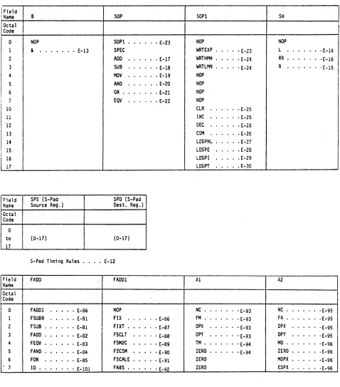
Each of the following fields may be used in any given instruction word.
B SOP SOPl
NOP SOPl • E-23 Nap
& • E-13 SPEC WRTEXP • E-23
AOD · E-17 WRTHMN . · E-24 SUB · £-18 WRTLMN · E-24 MOV · £-19 NOP
AND · E-20 NOP OR . · £-21 NOP EQV • E-22 NOP
CLR · £-25 INC · E-25 DEC · E-26 COM · E-26 LOSPNL · E-27 LOSPE • E-28 LDSPI · E-29 LOSPT · E-30
SPS (S-Pad SPO (S-Pad Source Reg.) Oest. Reg.)
(0-17) (0-17) S-Pad Timing Rules . . . • £-12
FAOO FADOl Al
FADOl · £-86 NOP Ne • £-93 FSUSR · £-81 FIX • E-86 fM . · E-93 fSUB • £-81
I FIXT • E-87 DPX · £-93
FA DO • E-82 FSeLT • £-88 Opy
· E-93
SH
NOP
L . E-14
RR . ·E-16 R . E-15
I
A2
I
[image:4.612.80.558.175.718.2]Field
Name CONO Octal
Code
0 NOP 1 if
2 BR 3 8INTRQ . 4 BION 5 BIOI 6 BFPE 7 RETURN 10 BFEQ 0
11 BFNE 12 BFGE 13 SFGT • 14 SEQ 15 SNE 16 BGE 17 BGT
Field
Name OPBS Octal
Code
0 ZERO . . E-129
1 INBS . . E-130 2 VALUE* . E-131
3 OPX
...
E-132 4 Opy E-133 5 MD . . . E-134 6 SPFN • E-1357 TM .• E-136
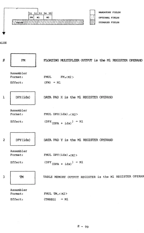
Field Name Ml Octal Code
0 FM •. · E-99 OPX
Unconditional Fields
Each of the following fields may be used in any given instruction word. DISP (Branch
Displ acement) DPX DPY
(0-37) NOP NOP
£-68 DB • · £-123 DB .
£-69 FA • · £-124 FA
E-70 FM. · E-125 FM.
E-70 E-71 E-71 E-72 E-73 E-74 E-75 E-76 E-77 E-78 E-79 E-80
XR (DPX YR (OPY XW (OPX YW (OPY Read Index) Read Index) Write Index) Write Index)
(0-7) (0-7) (0-7) (0-7)
M2 MI MA OPA
FA .
·
.
• E-I00 NOP NOP NOPDPX
·
.
FA •.
.
• E-137 INCMA •• E-140 INCOPA • . E-143I
I
i
. £-126 i I . E-127
o E-128
I I FM NOP FMUL TMA NOP
Field Name Octal Code 0 1 2 3 4 5 6 7 10 11 12 13 14 15 16 17 Field Name Octal Code 0 1 2 3 4 S 6 7 10 11 12 13 14 15 16 17 SPEC STEST HOSTPNl SPMOA NOP NOP NOP HOP
SPEC Fields
One of the SPEC Fields may be used per instruction word. The S-Pad Fields (B. SOP. SOPI. SH. SPS. and SPD) are then disabled for this instruction.
STEST HOSTPNl
·
.
• •• E-31 BFLT •.·
.
• • E-31 PNllIT ••· .
• E-39·
..
• E-39 BlT·
.
· .
• E-32 DBELlT .· .
• . £-39·
. ·
.
• E-6 BNC·
.
• • E-33 DBHLIT . • • E-40 BZC..
· .
• • E-34 DBllIT .• • •. E-40 BDBN .· .
• • £-35 NOPBDBZ •
·
..
• • E-36 NOP BIFN •· .
• • E-37 NOPSETPSA
JMPA*
·
..
• .E-45 JSRA*· .
· .E-46 JMP* ••·
.
• .E-47 JSR* .·
..
.£-47 JMPT •·
..
· .£-48 JSRT •· .
.E-48 JMPP ••· .
· .E-49NOP BIFZ • • •••• £-37 NOP JSRP •
· .
••• E-50SETPSA ••• · • £-45 NOP SWDB • · • ·E-41 NOP PSEVEN •
·
.
• . £-52 NOP SweSE·
.
• £-42 NOP PSODD·
.
·
.
• E-55 NOP SwaBH· .
· ·£-43 Nap PS ••· .
· .
• E-58 Nap SweBL • .E-44 Nap SETEXIT·
.
.
· E-66 BFLO •·
. ·
.
• E-38 Nap NOpNOP BFLl •
·
..
• • E-38 NOP NapNOP BFL2 •
· .
• • E-38 Nap NapNOP BFL3 •
·
.
• .• E-38 HOP NapPSEVEN PSODD PS SETEXIT
RPSOA* •
· .
• • E-52 RPSIA* •· .
• • E-55 RPSLA* .·
.
· 'E-58 NOP RPS2A* •· .
• • E-52 RPS3A* •• • •• E-55 RPSFA* .·
.
· ·E-59 SETEXA* RPSO*· .
·
.
• E-52 RPSl* • •••• E-55 RPSL*·
..
• . E-60 NOPRPS2*
· .
• •• E-52 RPS3*· ..
• • E-55 RPSF*· .
• . E-60 SET~X* .· .
RPSOT· .
• •• E-52 RPSlT· ..
• • E-56 RPSLT·
.
• ·E-60 NOPRPS2T
·
..
• • E-53 RPS3T·
...
• E-56 RPSFT • • ·E-61 SET EXT .· .
NOP NOP RPSLP
·
.
• •• E-61 NapNOP NOP RPSFP
·
...
· E-61 SETEXP •••WPSQA* •
·
.
• • E-53 WPSIA* .·
.
• • E-56 LPSLA* •• • . E-62 Nap WPS2A* •• • •• E-53 WPS3A* ••·
.
• E-56 LPSRA* .• • . 'E-63 HOP wpso*·
...
• E-54 WPSl*·
..
• • E-57 LPSl*·
..
· 'E-64 HOP WPS2*· ..
• E-54 WPSl*·
..
• • E-57 LPSR*·
..
· 'E-64 NOP WPSOT·
.
·
.
• E-54 WPSIT·
..
• • E-57 LPSLT·
.
'E-64 Nap WPS2T· ..
• • E-54 WPS3T·
..
• • E-57 LPSRT·
.
• • 'E-65 NOPHOP NOP LPSLP
· .
·
.
'E-65 NOPNOP Nap lPSRP
·
. ·
.
'E-65 NOPFormats for partial words (PSEVEN. PSODD. PS Fields) • . . . E-51
• .E.-66
• .E-66
• .E-67
Field Name Octal Code 0 1 2 3 4 5 6 7 Field Name Octal Code 0 1 2 3 4 5 6 7
I/O Fields
One of the I/O Fields may be used per instruction word. The Floating Adder Fields· (FADO. FAODI. AI. and A2) are then disabled for this instruction word.
I/O LOREG ROR£G I NOUT
LOR£G • £-101 NOP RPSA . '£~105 OUT
RC~£G · £-105 LDSPD · £-101 RSPD . '£-105 SPNOUT .
SPt-1DAV • £-7 LDMA . - £-101 RHA '£-106 OUTOA REX IT - £-7 LOTMA - £-102 RTHA • '£-106 SPOTOA
I HOur - £-109 LOOPA · E-I02 ROPA _ '£-107 IN _ SENSE - £-115 LOSP • - £-103 RSPFN '£-107 SPININ FLAG • • E-121 LOAPS - £-103 RAPS '£~108 INOA .
CONTROL -E-3 lOOA . • £-103 ROA '£-lOB SPINOA .
SENSE FLAG CONTROL
SNSA . - £-115 SFLO _ • £-121 HALT. '£-8 SPINA - £-115 SFLl • · £-121 IORST -E-9 SNSAOA • • E-115 SFL2 • · E-121 INl£N '£-9 SPNAOA . • E-115 SFL3 . - £-121 INTA _ ·£-10 SNSB . · £-118 CFLO _ • £-122 REFR • ·£-10 SPINS • £-118 CFLl • E-122 WRT£X '£-11 SNSSOA • • E-119 CFl2 • - £-122 WRTMAN ·£-11
SPNSOA . • £-120 CFL3 · £-122 NOP
Nap • • • • • • £-5
AP-120B Instruction Field Layout
0 1 2 3 4 5 6 7 8 9 10 11 12 1 14.15 16 17 18 19 20 21 22 23 24 25 26 27 28 29 30 31 alsop lSH
I
SPSI
SPD FADOI
1'.1I
A2 CONDI
DISPS-Pad Group Adder Group Branch Group
IsoPl I
l
FADDll
ISPEC OPER I I/O
o
value
all zeros
NOP No-operation
Assembler format: NOP
Effect: No operation is performed
63
i"
-.-;,.
"
MANDATORY FIELDS
OPTIONAL FIELDS DISABLED FIELDS
Description: The assembler recognizes this mnemonic and will insert an
IALUE
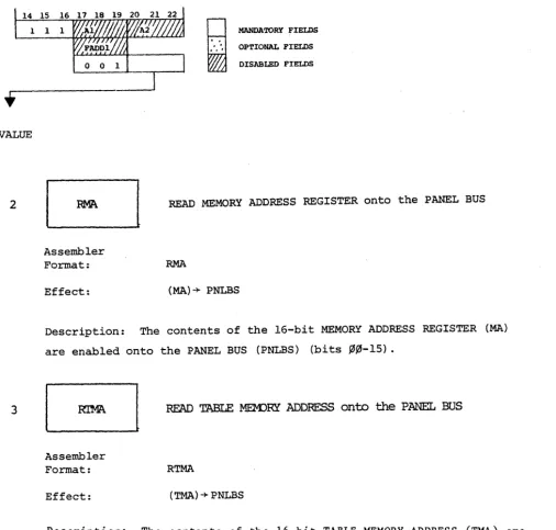
2
CONTROL (from SPEC
SPMDA
Assembler Format:
Effect:
MANDATORY FIELDS OPTIONJU, FIE:LDS DISABLED FIELDS
SPIN WHILE MAIN DATA BUSY
SPMDA
"SPIN" while MAIN DATA BUSY
Description: When specified, SPMDA causes the AP-l20B to suspend program execution until MAIN DATA MEMORY (MD) completes its READ or WRITE cycle a.nd becomes available for the next READ/WRITE operation. Using this op-code in an instruction immediately following one that initiates an MD READ operation, results in the data from that operation being available for use during the present instruction. It has no effect on a MD READ/WRITE operation in the same instruction.
Thus: LDMA; DB=lOO SPMDA; DPX(O)<MD
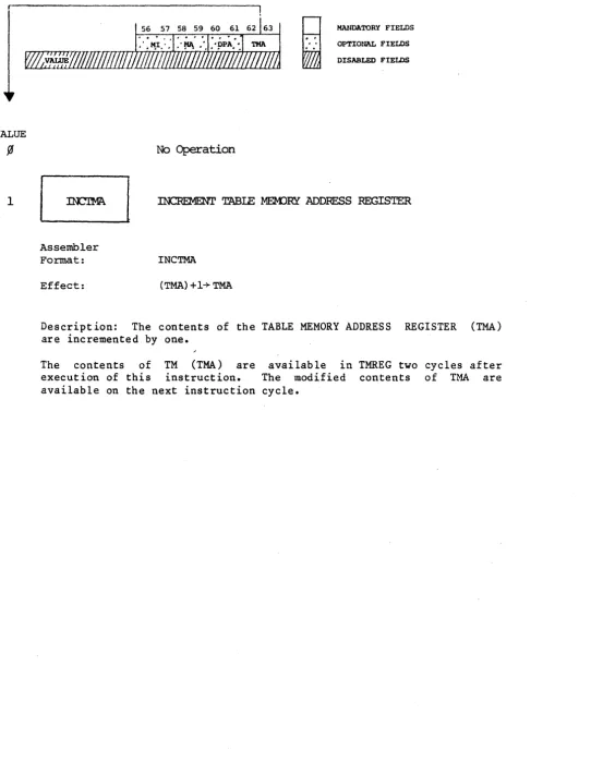
VALUE
2
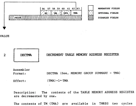
3
CONTROL (from I/O
SPMDAV
Assembler Format:
Effect:
~
..
..
..
.
MANDATORY FIELDS
OP'l'IONAL FIELDS
DISABLED FIELDS
SPIN tmLE MAIN DATA BUSY
SPMDAV
"SPIN" while MAIN DATA BUSY
Description: When specified, SPMDA causes the AP-l20B to suspend
program execution until MAIN DATA MEMORY (MD) completes its READ or
WRITE cycle and becomes available ·for the next READ/WRITE operation.
Using this op-code in an instruction immediately following one that
initiates an MD READ operation, results in the data from that operation
being available for use during the present instruction. It has no
effect on a MD READ/WRITE operation in the same instruction.
Thus: LDMA; DB=lOO
SPMDA; DPX(O)<MD
results in the contents of MD(lOO) being loaded into DPX(O).
REXIT
Assembler Format:
Effect:
READ EXIT
REXIT
!-\LUE
CONTROL F!ELD (CONTROL)
HALT
Assembler Format:
Effect:
H
~
HALT AP-120
HALT
MANDATORY FIELDS OPTIONAL FIELDS DISABLED FIEl:DS
example: INCMA; MI <FA; HALT
1 + FN
bit ~; clear RUN INDICATOR
Description: The AP-120B program execution will be halted after completion of the current instruction word. (See note.) AP-120B RUN INDICATOR (RUN) cleared and PANEL FUNCTION REGISTER(bit 0) set. When halted, PSA will point to the next instruction to be executed and it will have been entered into the instruction register. SPFN will
reflect the operation in that instruction.
tNOTE : if the current instruction "SPINS" while waiting for I/O or MEMORY, HALT will not be effective until the "SPIN" cycle is finished
and the instruction completed (as in the above example).
VALUE
1
2
CONTROL FIELD (CONTROL)
IORST
Assembler Format:
Effect:
~
..
..
..
.
MANDATORY FIELDS OPTIONAL FIELDS DISABLED FIELDS
RESET I/O DEVICES IMMEDIATELY
IORST
Clear I/O device logic and timing and all four of the general FLAGS.
Description: Effects are device dependent. No effect on Host interface,
TMRAM, or IOPI6.
INTEN
Assembler Format:
Effect:
n·1I'ERRUPT ENABLE
INTEN
If CTLBit ,05 is already set to "1", generate interrupt
to HOST-CPU. If not, no effect.
Description: This is used in conjunction with the CTLDS interrupt.
(See
Ilo
t PROGRAMMED INTERRUPTS.)When an INTEN is executed, the AP-120B will attempt to set CTLOS
interrupt. If CTL(Bit 05) is already set, then the AP-120B will
generate an interrupt to HOST-CPU. The state of CTL(Bit 05) is not
VALUE
3
4
CONTROL FIELD (CONTROL)
Assembler
Format:
Effect:
INTA
H
~
MANDATORY FIELDS
OPTIONAL FIELDS DISABLED· FIELDS
(DA interrupting IODEVICE)
"*
INBSDescription: The interrupting I/O DEVICE enables its Device Address
onto the INBS MANTISSA (Bits 20 to 27) for the current instruction
cycle. Used to identify the interrupting I/O device after an interrupt
is detected via the BINTRQ instruction.
Assembler
Format:
Effect:
MEM)RY REFRESH REQUEST
REFR
REFRESH MD! reset REFR CTR
Description: REFR initiates a REFRESH cycle to MAIN DATA MEMORY (MD).
The REFRESH COUNTER (REFR CTR) is reset to zero. This has the effect
of synchronizing the REFRESH timing with a running AP-120B program. It
VALUE
5
6
CONTROL FIELD (CONTROL)
Assembler Format:
Effect:
~
,"
," ,
MANDATORY FIELDS
OPTIONAL FIELDS
DISABLED FlEWS
NRlTE EXPONENT ONLY
WRTEX
example: DPX (2) < TMi WRTEX
Restricts DPX, DPY, or MI fields to write exponent bits only.
Description: When specified with a concurrent WRITE DPX, DPY, or MI
operation, WRTEX restricts the wr1t1ng to EXPONENT(Bits 02-11) only.
(See S-PAD group, WRTEXP for further description of effect.)
EJ
Assembler Format:
Effect:
WRITE MANTISSA ONLY
WRTMAN
Example: MOV 5,5; SETMA; MI < FA; WRTMAN
Restricts DPX, DPY, or MI fields to WRITE MANTISSA bits only.
Description: When specified with a concurrent WRITE DPX, DPY or MI
operation, WRTMAN restricts the wr1t1ng to MANTISSA(Bits 00-27) only.
7
Assembler Format:
Effect:
IOINTA
IOINTA
CONTROL FIELD (CONTROL) continued ...
I/O INTERRUPT ACKNOWLEDGE
(DA interrupting IODEVICE) INBUS
Description: The interruptiong I/O Device enables its Device Address
S-PAD TIMING RULES
1. SPFN for an instruction with an S-PAD operation is the result of that operation.
2. SPFN is stored back into SP(SPD) only once - at the end of the
instruction in which the S-PAD operation took place (not
stored at all if No-Load specified). Similarly, the N, Z, and C S-PAD condition bits are set only once for each S-PAD
operation.
3. SPFN for an instruction without an S-PAD operation is the
result of performing the last previous S-PAD instruction over again, using the current value of SP(SPD) as possibly modified
by the original S-PAD operation. SP(SPD) is not altered if no
S-PAD operation is specified. This modified SPFN value would be apparent if an SPFN utilizing instruction were executed
VALUE
1
BIT REVERSE FIELD
Assembler Format:
Effect:
Effect:
~
..
.
, , OPTIONAL FIELDS MANDATORY FIELDS
DISABLED FIELDS
No Operation
BIT REVERSE the contents of S-PAD SOURCE REGISTER before using
< & > (Brackets indicate optional use with S-PAD operations.) Example: ADD & 6,5
BIT-REVERSE(SP
SPS)-+ SOURCE INPUT FOR CURRENT S-PAD OPERATION
Description: The contents of the S-PAD SOURCE REGISTER (SP(SPS]) are
BIT-REVERSED and shifted before being used as the SOURCE OPERAND in the current S-PAD operation.
The number of shifts performed depends on the S1ze of the complex data
array being processed. The programmer must load the applicable shift
value into the BIT-REVERSE field of the APSTATUS Register before
specifying the BIT-REVERSE operation. (See S-PAD SUMMARY BIT-REVERSE
SHIFT FIELD
5 6 7 8 9 10 11 12 13 t:-:--:r-- - - - r - - - - y - - - . - - - i
i·
VALUE
1
Assembler Format:
Effect:
SPS SPD
..
.
.
SOPl *
No Operation
MANDATORY FIELDS OPTIONAL FIELDS DISABLED FIELDS
* MAY BE USEP WITH EITHER SOP OR SOP1 FIELDS
LEFT SHIFT S-PAD OUI'PUI' (SPFN) ONCE. ZERO FILL.
<L> (Brackets indicate optional use with S-PAD operations)
Example: SUBL 5,6
SPFN~ LEFT SHIFTED ONCE~ SPFN
Description: The S-PAD RESULT (SPFN) is logically shifted left one
place. The right-most bit is set to zero. The bit shifted off the
left end is stored in the S-PAD CARRY BIT, (C) - overriding any carry that resulted from the specified arithmetic operation.
Excepting possible OVERFLOW, the shift has the effect of a
multiplication by two. The carry bit (C), bit 7 of the AP INTERNAL
STATUS REGISTER (APSTATUS), may be tested during the next instruction cycle.
VALUE
2
SHIFT FIELD (SH)
5 6 7 8 9 10 11 12 13
--,---
---r---~~
.
Assembler Format:
Effect:
SPS
soP 1
SPD
*
..
..
MANDATORY FIELDS
OPTIONAL FIELDS
DISABLED FIELDS
* MAY BE USED WITH EITHER SOP OR sopl FIELDS
RIGHT SHIFT S-PAD FUNcrION (SPFN) ONCE. ZEro FILL.
< R > (Brackets indicate optional use with S-PAD operations)
Example: SUBR 5,6
SPFN right-shifted once+ SPFN
Description: The S-PAD RESULT (SPFN) is logically shifted right one
place. A zero is shifted into the left-most bit. The bit shifted off the right end is set into the S-PAD CARRY BIT.
The instruction has the effect for unsigned numbers, of a division by
two. Bit C of the AP INTERNAL STATUS REGISTER (bit 7, APSTATUS)
reflects the condition of S-PAD CARRY and may be tested during the next instruction cycle.
15
SHIFT FIELD
5 6 7 8
~~---~--~ 9 10 11 12 13
SPD
i·
'
VALUE
3
Assembler Format:
Effect:
SPS
SOP 1
..
..
MANDATORY FIELDS OPTIONAL FIELDS DISABLED FIELDS
* MAY BE USED WITH EITHER SOP OR SO~1 FIELDS
RIGHT SHIFT S-PAD FUNCTION (SPFN) twice. Zero fill.
<RR> (Brackets indicate optional use with S-PAD
operations)
E~ample: SUBRR 5,6
SPFN -+ right shifted twice+ SPFN
Description: The contents of the, S-PAD ALU RESULT are logically
shifted right two times before being enabled onto the SPFN data path. Zeros are filled into 'the left-most two bits. The second bit shifted off the end is set into the S-PAD ALU CARRY BIT.
The instruction has the effect for unsigned numbers of a division by
four. Bit C (bit 7) of the AP INTERNAL STATUS REGISTER (APSTATUS)
reflects the condition of the S-PAD CARRY BIT and may be tested during the next instruction cycle.
(
15, _ • REFLECTS THE CONTENTS OF THESPFN
~
~
SECOND BIT SHIFTED "OFF THE END"VALUE
Y'
12
S-PAD OPERATIONS FIELD
Assembler Format:
Effect:
SPD
~
.
..
'
.
See, S-PAD OPERATIONS 1 See, SPECIAL OPERATIONS
MANDATORY FIELDS
OPTIONAL FIELDS
DISABLED FIELDS
ADD S-PAD SOURCE REGISTER AND S-PAD DESTINATION REGISTER
ADD < # > < & > SPS, SPD
t tt
(SP
SPS) plus (SPSPD)+ SPFN
SPFN+(SP
SPD) unless S-PAD NO-LOAD(#) is specified
Description: The contents of S-PAD SOURCE REGISTER (SP
sPS) are added with the contents of S-PAD DESTINATION REGISTER (SP
SPD). The result of the operation, (SPFN) is stored back into the specified S-PAD
DESTINATION REGISTER unless an S-PAD NO-LOAD (#) is specified.
Appropriate bits are set in the AP INTERNAL STATUS REGISTER
(APSTATUS) and may be tested during the next instruction cycle.
CARRY BIT EQUATION: If (SP SPD) + (SP SPS)
~
216 then carry=lt (SP
sPS) may be optionally BIT-REVERSED, (see BIT-REVERSE FIELD)
tt
S-PAD OPERATIONS FIELD
~_r-_~---::"''''''''''_''':'_r-'-6 7 8 9 l_~-.l~-.!2 SPD
H
Wj
MANDATORY FIELDS OPTIONAL FIELDS DISABLED FIELDS
VALUE
3
Assembler Format:
Effect:
SUBtract S-P.AD SOURCE REGISTER fran S-PAD
DESTINATION REGISTER
SUB< sh >< # > < & > sps, spd
·t tt
(SPSPD)minus (SP
sPS) +SPFN ;
SPFN+ (SP
SPD) unless S-PAD NO-LOAD (#) is specified
Description: The contents of the S-PAD SOURCE REGISTER are subtracted
from the contents of the S-PAD DESTINATION REGISTER. The result of the
operation is stored back into the S-PAD DESTINATION REGISTER unless a
S-PAD NO-LOAD (#) is specified.
Appropriate bits (N,Z,C) are set in the AP INTERNAL STATUS REGISTER
(APSTATUS) and may be tested during the next instruction cycle.
CARRY BIT EQUATION: If (SP[SPD])+(SPlSPS])+l
~
216 then C=l else O.If a shift is specified, then C is set to the carry from that shift.
VALUE
4
S-PAD OPERATIONS FIELD
Assembler Format:
Effect:
6 7 8 9
~
..
..
.
'.
MANDATORY FIELDS OPTIONAL FIELDS DISABLED FIELDS
mvE S-PAD SOURCE REGISTER TO
S-PAD DESTINATION REGISTER
MOV < sh > < # > < & > sps, spd (SPSPS)t+ SPFNtt; SPFN+ (SP
SPD) unless S-PAD
NO-LOAD is specified.
Description: SPFN is set to the contents of the S-PAD SOURCE REGISTER
(SP[SPS]); SPFN is stored into the S-PAD DESTINATION REGISTER unless
an S-PAD NO-LOAD (#) is specified.
Appropriate bits are set in the AP INTERNAL STATUS REGISTER (APSTATUS)
and may be tested during the next instruction cycle.
CARRY BIT EQUATION:
(Sp[sPS])]~ 216
If [(SP[SPD]) AND (Sp[SPS])] + [(SP[SPD]) OR
then, C=l else 0
~SP[SPS]) may be optionally BIT-REVERSED. See BIT-REVERSE FIELD.
VALUE
5
S-PAD OPERATIONS FIELD
--,-_6 ___ 7 _8 _~ .l:_<!_~J_-±L_!3
SPD MANDATORY FIELDS
~
..
.,
" ,
I
OPTIONAL FIELDS DISABLED FIELDS
AND S-PAD SOURCE REGISTER to S-PAD DESTINATION REGISTER
Assembler Format:
Effect:
AND < sh > <#> < & > sps,spd
(SPSPS)t AND
(SPSPD)~
SPFNtt;SPFN ~ (SP SPD) unless S-PAO NO-LOAD is specified.
Description: The contents of the S-PAO SOURCE REGISTER (SP
sPS) are logically ANDed with the contents of the S-PAD DESTINATION REGISTER
(SP
SPD). A bit by bit comparison is made between the contents of the two operands and if both respective bits are "1", a "1" is recorded
into the correspondi~g bit of the result (SPFN). All other
combina-tions result in ".0" being recorded into the respective bit of SPFN. The result of the operation (SPFN) is stored into SPSPD"unless an
S-PAD NO-LOAD (#) is specified.
The appropriate bits are set in the AP INTERNAL STATUS REGISTER
(APSTATUS) and may be tested during the next instruction cycle.
16
CARRY BIT EQUATION: If [(SP SPO) AND (SP SPS) ] + (SP SPO) ~ 2 then CARRY=l
TRUTH TABLE
SP
SPS SPSPD SPFN
•
~A
VALUE
6
S-PAD OPERATIONS FIELD
Assembler Format:
Effect:
5 6 7 8 9
~
Wj
MANDATORY FIELDS
OPTIONAL FIELDS
DISABLED FIELDS
OR S-PAD SOURCE REGISTER to S-PAD DESTlNATION REGIS~
OR < sh > < # > < & > sps, spd
t tt
(SP
SPS) OR (SPSPD)~ SPFN;
SPFN ~ (SP
SPD) unless NO-LOAD is specified.
Description: The contents of the S-PAD SOURCE REGISTER (Sp[SPS]) are
logically ORed with the contents of the S-PAD DESTINATION REGISTER
(SP[SPD]). A bit-by-bit comparison is made between the contents of the
two operands and if either one of the respective bits
=
"1," then a "1"is recorded in the corresponding bit of the result (SPFN). All other
combinations result in a "0" being recorded into the respective SPFN
bit position. The result of the operation (SPFN) is stored into
SP(SPD) unless S-PAD NO-LOAD (#) is specified.
Additionally, S-PAD ALU CARRY BIT is set to "0." The appropriate bits of the AP INTERNAL STATUS REGISTER (APSTATUS) are set and may be tested during the next instruction cycle.
TRUTH TABLE
SP
SPS SPSPD SPFN
Y
Y
~~ ~
•
~~ 1 ~ 1
1 ~
•
1VALUE
7
S-PAD OPERATIONS FIELD
~ __ -:---r_6 _ _ 7 ._8_9 l:.Q .. !'!'" 12 13
~
..
Assembler Format:
Effect:
SPD
..
.
'.
MANDATORY FIELDS
OPTIONAL FlEWS DISABLED FIELDS
EQUIVALENCE S-PAD SOURCE REGISTER to S-PAD DESTINATION REGISTER
EQV < sh > < # > < & > sps, spd
t - . tt
(SP
SPS) XOR (SPSPD)+ SPFN i
SPFN + (SP SPD) unless NO-LOAD is specified.
Description: The contents of the S-PAD SOURCE REGISTER (SP[SPS]) and
the S-PAD DESTINATION REGISTER (SP[SPD]) are compared on a
corresponding bit position basis for equal value. If the corresponding
bits both equal "0," or both equal "1," then the respective bit of the result (SPFN) is set to "l.tt All other combinations result in a "0"
being set into the corresponding bit of SPFN. The result of the
operation (SPFN) is then written into (SP[SPD]) unless S-PAD NO-LOAD
(#) is specified.
The appropriate bits are set in the AP INTERNAL STATUS REGISTER
(APSTATUS) and may be tested during the next instruction cycle.
I~
I
BJ
~
VALUE
1
S-PAD OPERATION 1 FIELD
1 2 3 4 5 6 7 8 9 10 11 l4! 13
I
I
- r---'"I
SOP SH SPS SPD 19.NDATORY FIELDS
SOP1
...
OPTIONAL FIELDS SPEC OPERI
~
~ DISABLED FIELDSEJ
Assembler Format:
Effect:
RESTRIcr WRITE m EXPonent only into DPX, DPY or MI
WRTEXP
Example: DPX (-2) FA; WRTEXP
Restricts DPX,DPY or MI field to write EXPONENT bits only.
Description: WRTEXP restricts writing of the pertinent MEMORY INPUT
REGISTER into EXPONENT bits 02-11 only. WRTEXP used in conjunction
with a DPX, DPY or MI WRITE operation.
When used in conjunction with a WRITE DPX or WRITE DPY operation, this
operation has the effect of concatenating a portion of the input data
with the value most recently written into DPX or DPY irrespective of XW
or YW. Thus, if the last WRITE into DPX placed a floating point 1.0
into DPX(-2) and in this instruction we WRITE DPX(O) in conjunction
with the WRTEXP Op-Code, the net effect is to concatenate the EXPONENT portion of the current input with the MANTISSA from the 1.0 of the
preceding DPX WRITE operation and place the result in DPX(O). WRTHMN,.
WRTIMN act in a similar fashion with the exception that they use
VALUE
2
3
S-PAD OPERATIONS 1 FIELD
4
Assembler Format:
Effect:
5
SH
6 7 B 9 10
SPS SPO
~
MANDATORY' FIELDS SOP1...
OPTIONAL FIELDS SPEC OPER DISABLED FIELDSRESTRICT WRITE TO HIGH MANTISSA only into DPX,
DPY or MI
WRTHM.N
Example: WRTHMN i DPY < FM
Restricts DPX, DPY or MI fields to WRITE HIGH
MANTISSA bits only (MANTISSA bits ~~-11) .
Description: WRTHMN restricts the writing to the HIGH MANTISSA only,
(MANTISSABITS
~~-ll)
of the pertinent MEMORY INPUT REGISTER. WRTHMN is used in conjunction with a DPX, DPY or MI WRITE operation. (Seeexample above).
NOTE: See WRTEXP for a description of the effect of this operation on
DPX or DPY.
Assembler Format:
Effect:
RESTRIC'r WRITE to I.J::1i/ MANI'ISSA only into DPX,
DFY
or
MI FIELDSWRTLMN'
Example: WRTLMN i SETMA; MI < MD
Restricts DPX, DPY or MI fields to WRITE LOW MANTISSA
S-PAD OPERATIONS 1 FIELD
4 5 6 7 8 9 10 11 12 13 . - - - .
SH SPS SPD MANDATORY FIElDS
~
OPTIONAL FIELDSSOPI
..
SPEC OPER DISABLED FIELDS
•
VALUE
4 through 7 No Operation
10
11
Assembler Format:
-Effect:
CLEAR S-PAD DESTINATION REGISTER
CLR < sh> <#> spd
~-+SPFN; ~+SPSPD unless NO-LOAD (#) is specified.
Description: The S-PAD OUTPUT (SPFN) is forced to all zeros and bit
"z"
of the AP INTERNAL STATUS REGISTER is set to "1" (bit 5, APSTATUS).SP(SPD) is cleared unless S-PAD NO-LOAD (#) is specified.
CARRY BIT EQUATION: If SP(SPD) is negative then CARRY=i.
Assembler Format:
Effect:
INCREMENT S-PAD DESTINATION REGISTER
INC < sh > < # >spd
(SP
SPD) + 1 -+ SPFN; and, unless NO-LOAD is specified,
Description: The contents of the S-PAD DESTINATION REGISTER (SP[SPD]),
plus ONE are enabled onto the S-PAD FUNCTION (SPFN). SPFN is stored
VALUE
12
13
S-PAD OPERATIONS 1 FIELD
4 5 6 7 8 9 1 0
S8 SPS SOpl SPEC OPER
SPD
~
Wj
MANDATORY FIELDS OPTIONAL FIELDS DISABLED FIELDS
DECREMENT S-PAD DESTINATION REGISTER
Assembler
Format: DEC < sh> < #> spd
Effect: (SP SPD) -1+ SPFN; and, unless NO-LOAD is specified,
(SPFN) + SP SPD
Description: Tne contents of the S-PAD DESTINATION REGISTER minus ONE is
set to the S-PAD Function (SPFN). The result (SPFN) is stored into the
S-PAD DESTINATION REGISTER unless S-PAD NO-LOAD (#) is specified.
The appropriate bits of the AP INTERNAL STATUS REGISTER (APSTATUS)
will be set and may be tested during the next instruction cycle.
CARRY BIT EQUATION: Unless SP
SPD was ~, CARRY=l.
Assembler Format:
COMPI»1ENT S-PAD DESTINATION REGISTER
COM < sh > <: # > spd Effect: (SP
SPD)+ SPFN; unless NO-LOAD is specified,
VALUE
14
S-PAD OPERATIONS 1 FIELD
4 5 6 7 8 9 10 11 12 13
-SH SPS SPD f4ANDA'l'OR'i FIELDS SOP 1
~
.. OPTIONAL FIELDS SPEC OPER DISABLED FIELDSWAD S-PAD DESTINATION REGISTER frcm the PANEL BUS
Assembler
Format: LDSPNL spd
Effect: (SP SPD) -7 SPFNi PNLBS -7 SP SPD
Description: First, the S-PAD Function is set to the old contents of the
S-PAD DESTINATION REGISTER. Then, whatever is enabled qnto the PANEL BUS
is loaded into the S-PAD DESTINATION REGISTER.
The appropriate bits of the AP INTERNAL STATUS REGISTER (APSTATUS)
are set as determined by the previous contents of SP
SPD and may be tested during the next instruction. S-PAD CARRY is set to one. If no S-PAD
operation is done in the next instruction, then SPFN for that instruction
will be the new contents of SP
SPD as loaded by this instruction cycle
FIRST: THEN:
15 15
SP
SPD PNLBS
S-PAD OPERATIONS 1 FIELD
5 6 7 8 9 10
~~---,----.-Q
~
VALUE
15
S8
Assembler
Format:
Effect:
SPS SPD
SOPl SPEC OPER
MANDATORY FIElDS OPTIONAL FIELDS DISABLED FIELDS
wad S-PAD DESTINATION REGIS'IER from
DATA PAD BUS - EXPONENT
t
LDSPE spd (SP
SPD)+ SPFNi then, (DPBS EXP
) -5l2+SP SPD
Description: First, the SPFN is set to the old contents of the S-PAD
DESTINATION REGISTER. Then the EXPONENT portion of the DATA PAD BUS
(bits 02-11), BIAS inverted, is loaded into the S-PAD DESTINATION
REGISTER (bits 06-15). The inverted EXPONENT BIAS BIT is extended into
the remaining portion of SP(SPD) (bits 00-05).
The appropriate bits of the AP INTERNAL STATUS REGISTER (APSTATUS) are
set as determined by the previous contents of SP(SPD) and may be tested
during the next instruction. S-PAD CARRY is set to one. If no S-PAD
operation is done in the next instruction, then SPFN for that
instruction will be the new contents of SP(SPD) as loaded by this
instruction.
I
~I
BI
VALUE
16
S-PAD OPERATIONS 1 FIELD
1 2 3 4 5 6 sOP
I
SHAssembler
7 0 9 10 SPS
SOP1 SPEC OPER
11 12
131
-SPD
1
I
H
~
MANDATORY FIELDS OPTIONAL FIELDS DISABLED FIELDS
wad S-PAD DESTINATION REGISTER fran DATA PAD BUS - INTEGER
Format: LDSPI spd
Effect: (SPSPD)~ SPFN, then (DPBS LOW MANTISSA)~ SPSPD Description: First, SPFN is set to the old contents of the S-PAD
DESTINATION REGISTER. Then the contents of the DATA PAD BUS - LOW
MANTISSA, a 16-bit integer, are loaded into the S-PAD DESTINATION
REGISTER.
The appropriate bits of the AP INTERNAL STATUS REGISTER (APSTATUS)
are set as determined by the previous contents of SP
SPD and may be tested during the next instruction. S-PAD CARRY is set to one. If no
S-PAD operation is done in the next instruction, the SPFN for that
in-struction will be the new contents of SP
I
~I
BI
~
VALUE
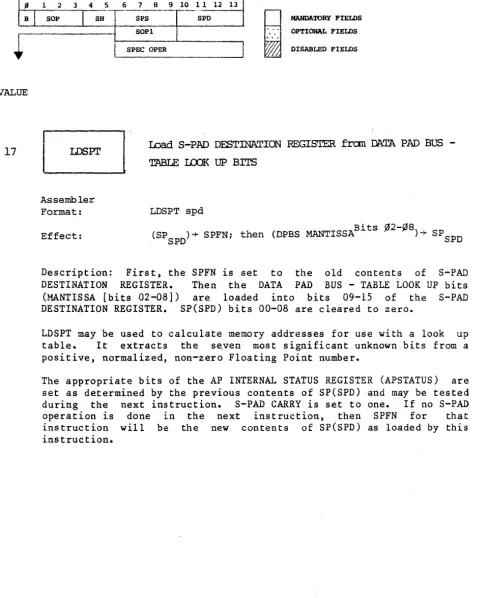
17
S-PAD OPERATIONS 1 FIELD
1 2 3 4 SOP
I
Assembler Format: Effect:
5 6 SH
7 8 9 10 11 12
-_
... 13I
SPS SPD
j
MANDATORY FIELDS SOPl~
...
OPTIONAL FIELDS. SPEC OPERI
DISABLED FIELDSwad S-PlID DESTINATION REGISTER fran mTA PAD BUS
-TABLE LCOK UP BITS
LDSPT spd
(SP )+ SPFN; then (DPBS MANTISSABits
~2-fJ8)+
SP. SPD SPD
Description: First, the SPFN is set to the old contents of S-PAD
DESTINATION REGISTER. Then the DATA PAD BUS - TABLE LOOK UP bits
(MANTISSA [bits 02-08]) are loaded into bits 09-15 of the S-PAD
DESTINATION REGISTER. SP(SPD) bits 00-08 are cleared to zero.
[image:34.624.48.536.83.768.2]LDSPT may be used to calculate memory addresses for use with a look up
table. It extracts the se.ven most significant unknown bits from a
positive, normalized, non-zero Floating Point number.
The appropriate bits of the AP INTERNAL STATUS REGISTER (APSTATUS) are
set as determined by the previous contents of SP(SPD) and may be tested
during the next instruction. S-PAD CARRY is set to one. If no S-PAD
operation is done in the next instruction, then SPFN for that
instruction will be the new contents of SP(SPD) as loaded by this
[image:34.624.35.524.91.690.2]VALUE
SPECIAL TEST FIELD (STEST)
Assembler Format: Effect:
Description:
branch if
o 0 0 0
H
~
MANDATORY FIELDS
OP'1':IONAL FIELDS DISABLED FIELDS
BRANCH on FLOATING ADDER LESS THAN ZEID
BFLT targ
If FA < 0; then (PSA) + (DISP t - BIAS) -+- PSA (where BIAS
=
2°8).
CONDITIONAL RELATIVE BRANCH. BFLT will cause a program
the FADDR Result (FA) available during the previous
instruction was less than zero.
This instruction tests the FA-NEGATIVE Bit (FN) of the APSTATUS
Register. If FN is equal to "1" (indicating that FA was negative
during the previous instruction) a program branch will occur to ,the
BRANCH TARGET ADDRESS (targ) formed by adding the current contents of
PSA with Biased contents of the DISP field of the current instruction word. If FN is equal to "0," this instruction will have no effect.
The BRANCH TARGET ADDRESS must lie within -20(8) to +17(8) locations
relative to the current PROGRAM SOURCE ADDRESS.
DISP=Instruction Word (BITS 27-31) is computed as follows: DISP =
targ (PSA) + BlAS. Note that if FN was altered via a LDAPS
instruction, at least one cycle must intervene before testing it with
this instruction. This restriction applies to all BRANCH instructions
VALUE
1
SPECIAL TEST FIELD (STEST)
Assembler Format:
Effect:
o 0 0 0
H
~
MANDATORY FIELDS OPTIONAL FIELDS DISABLED FIELDS
BRANCH if S-PAD FUNCTION is LESS THAN ZERO
BLT targ
t
If SPFN < 0; then (PSA) + (DISP - BIAS) + PSA (Where BIAS = 2°
8).
Description: CONDITIONAL RELATIVE BRANCH. BLT will cause a program
branch if the result of the last S-PAD operation (SPFN) was less than zero.
This instruction tests the condition of the SPFN-NEGATIVE Bit (N) of
the APSTATUS Register. If "N" is equal to "1" (indicating that SPFN of
the last previous instruction was negative), a program branch will
occur to the BRANCH TARGET ADDRESS (targ) formed by adding the current
contents of PSA with the BIASED contents of the DISP field of the
VALUE
2
SPECIAL TEST FIELD (STEST)
o 0 0 0
~
.
..
.
.
MANDATORY FIELDS OPTIONAL FIELDS DISABLED FIELDSBRANaI if S-PAD CARRY is equal to "1"
Assembler
Format: BNe targ
Effect: If S-PAD CARRY
=
Ii then (PSA) + (OISpt - BIAS)~
PSA (Where BIAS=
208
>.
Description: CONDITIONAL RELATIVE BRANCH. BNC will cause a program
branch if the S-PAD CARRY Bit (C) of the APSTATUS Register is equal to
"1."
Bit "C" will be equal to "1" if either:
*the S-PAD CARRY Bit was set to "1" as a result of the last S-PAD operation and no S-PAD SHIFT was specified, or
VALUE
3
SPECIAL TEST FIELD (STEST)
Assembler Format:
Effect:
0 0 0 0
~
~
MANDATORY FIELDS
OPTIONAL FIELDS CIS1\BLED FIELDS
BRANaI
on
S-PAD CARRY equal to ZEROBZC targ
If S-PAD CARRY
=
~;
then (PSA) + (DISpt - BIAS) + PSA(Where BIAS
=
208).Description: CONDITIONAL RELATIVE BRANCH. BZC will cause a program
VALUE
4
SPECIAL TEST FIELD (STEST)
o 0 0 0
H
~
MANOlo\TORY FIELDS
OPTIONAL FIELDS DISABLED FIELDS
BRANCli if DATA PAD BUS is NEG\TIVE
Assembler
Format: BDBN targ
Effect: If (DB) < 0.0; then (PSA) + (DISP t - BIAS) -+ PSA
(Where BIAS = 2° 8).
Description: CONDITIONAL RELATIVE BRANCH. The sign of the DATA PAD
BUS (MANTISSA) (DB[MANT]bit 00) is tested as to its state during the
preceding instruction. If DB(MANT)Bit 00 was negative, (e.g.,=l), a
program branch will occur to the BRANCH TARGET ADDRESS (targ) formed by
adding the current contents of PSA with the BIASED contents of the
DISP field of the current instruction word. If DB(MANT)Bit 00 was
"0," this instruction will have no effect.
NOTE: Since any data enabled onto DB is not latched, the programmer
must re-enable the particular data onto DB one instruction cycle before attempting to test it with this instruction.
Note that instructions in the PS field (RPSF, LPSL, etc.)
used to enable data onto Data Pad Bus for testing
instruction.
VALUE
5
SPECIAL TEST FIELD (STEST)
Assembler Format:
Effect:
0 0 0 0
~
",
..
.
,MANDATORY FIELDS OPTIONAL FIELDS DISABLED FIELDS
BRANCH if DATA PAD ,Btl:) is POSITIVE and UNNORMALIZED
BDBZ targ
If DBMANTBits
~fi1,fi1l
=
"fi1", then (PSA) + (DISpt - BIAS)' -+ PSA (Where BIAS=
208).Description: CONDITIONAL RELATIVE BRANCH. BDBZ will cause a program
branch to occur to the BRANCH TARGET ADDRESS (targ), formed by adding
the current contents of PSA with the BIASED contents of the DISP field
of the current instruction word, if the sign of the DATA PAD
BUS (MANTISSA) (DB [MANT]Bit 00), enabled during the preceding
instruction, was positive (e.g.,=O) and DB(MANT)Bit 01 was also equal
to "0," (indicating an UNNORMALIZED MANTISSA). If either or both Bits equal(s) "1," this instruction will have no effect.
NOTE: Since any data enabled onto DB is not latched, the programmer
must re-enabl~ the particular data onto DB one cycle before attempting
SPECIAL TEST FIELD (STEST)
o 0 0 0
VALUE
~
.
..
.
.
MANDATORY FIELDS OPTIONAL FIELDS DISABLED FIELDS6~
BRANCH if INVERSE FFl' FIAG=
1 AssemblerFormat:
Effect:
BIFN targ
Bit 11
If IFFT (APSTATUS ) = 1; then (PSA) + (DISP t - BIAS) -+ PSA (Where BIAS
=
208).Description: CONDITIONAL RELATIVE BRANCH. BIFN will cause a program branch if the Inverse FFT Flag (IFFT) of the APST~TUS Register is set to "I."
IFFT is APSTATUS(bit 11) and can be set by an LDAPS instruction. (See LDREG, I/O.) It is normally set to "1," along with APSTATUS(bit 12)
(FFT), only during an INVERSE FAST FOURIER TRANSFORM.
7
c::=J
Assembler Format:
Effect:
BRANCH if IFFT FIAG = 0
BIFZ targ
If IFFT (APSTATUsBi t 12) = ¢; then (PSA) = (DISP t - BIAS) -+ PSA (Where BIAS = 208).
'ALUE
SPECIAL TEST FIELD (STEST)
Assembler Format:
Effect:
o 0 0 0
No Operation
~
.
..
.
.
MANDATORY FlEWS OPTIONAL FIELDSDISABLED FIELDS
BRAN:li if GENERAL FIAG #~
=
1BRAN:li if BENERAL FI.AG #1
=
1BlWOi if GENERAL FI.AG #2 = 1
BlWOi if GENERAL FI.AG #3
=
1BFLn targ
If FLAG n=li then (PSA) + (DISpt - BIAS) + PSA
(Where BIAS = 208).
Description: A branch will occur to program location "targ" (assembler format) if flag "n" is set to "1." Flag "n" must have been set or cleared two cycles before the current instruction cycle in order to be
tested, i.e., at least one cycle must interven~ between a set or clear
flag instruction and a branch flag instruc.tion.
';;1 ..
Note: The CONDITIONAL RELATIVE BRANCH instructions test the
condition of either of four GENERAL FLAGS (0,1,2,3) available for use in the AP. These flags may be "set" or "cleared" by
VALUE
1
HOST/PANEL FIELD (HOSTPNL)
MANDATORY FIELDS
~
..
OPTIONAL FIELDS0 0 0 1 DISABLED FIELDS
TRANSFER PANEL BUS to the LITES REGISTER
Assembler
Format: PNLLIT
Effect: (PNLBS) ~ LITES
Description: The current data enabled onto the 16-bit PANEL BUS are loaded
into the 16-bit LITES REGISTER.
EJ
Assembler
TRANSFER DATA PAD BUSEXPONENT to the LITES REGISTER,
via
PANEL BUSFormat: DBELIT
Effect: (DBEXP) PNLBS ~ LITES; right justified.
Description: The current data enabled onto the IO-bit DATA PAD BUSEXPONENT
are loaded into the 16-bit LITES REGISTER - right justified. The transfer
+
VALUE
2
HOST/PANEL FIELD (HOSTPNL)
Assembler Format:
Effect:
o 0 0 1
~
~
MANDATORY FIELDS OPTIONAL FIELDS DISABLED FIELDS
TRANSFER DATA PAD BUS - HI<1I MANTISSA to the LITES
REGIS'mR, via PANEL BUS
DBHLIT
(DBHMANT) + PNLBS + LITES; right justified
Description: The current data enabled onto the DATA PAD BUSHIGH MANTISSA
(MANTISSABits
~~-11)
are loaded into the 12 right-most bits of the LITESREGISTER. The transfer is via PANEL BUS.
Assembler Format:
Effect:
TRANSFER DATA PAD BugICM MANTISSA to the
LITES REGISTER, via PANEL BUS
DBLLIT
(DBLMANT) + PNLBS + LITES
Description: The current data enabled onto the DATA PAD BUSLOW MANTISSA
HOST/PANEL FIELD (HOSTPNL)
0 0 0 1
VALUE
H
Wj
MANDATORY FIELDS OPTIONAL FIELDS DISABLED FIELDS
+ 8
l~~
No Operation
TRANSFER SWITCHES to the DA'm PAD BUS, via PANEL BUS
Assembler Format:
Effect:
SWDB
Example:
(SWRBits
(SWRBits
(SWR)
DPX (1) < DB; SWDB
~6-l5)---+ DBEXP Bits ~2-11,
}
~4-15)---+ DBMANTBits ¢¢-11, via PNLBS
) DBMANTBits 12-27.
Description: The current contents of the l6-bit SWITCH Register (SWR)
are enabled onto the DATA PAD BUS (DB) in the following manner:
SWR(bits 06-15) are enabled onto the DATA PAD BUS(EXPONENT),
SWR(bits 04-15) are enabled onto the DATA PAD BUS(HIGH MANTISSA), and
SWR(bits 00-15) are enabled onto the DATA PAD BUS(LOW MANTISSA) •
The transfer is via PNLBS.
This instruction is used concurrently with a write from DATA PAD BUS
+
VALUE
11
HOST/PANEL FIELD (HOSTPNL)
MANDATORY FIELDS
0 0 0 1
H
WlJ
OPTIONAL FIELDS DISABLED FIELDS
Assembler Format:
Effect:
TRANSFER SWITCHES to the DATA PAD BUSEXPONENT
via PANEL BUS
SWDBE
Example: DPY ( - 2) < DB; SWDBE
(SWRBits ~6-15)---+ DBEXP Bits ~2-11,
(SWRBits ~4-15)---+ DBMANTBits ~~-ll,
(SWR)---+) DBMANTBits 12-27.
via PNLBS; WRTEXpt is forced
Description: The current contents of the 16-bit SWITCH Register (SWR)
are enabled onto the DATA PAD BUS (DB) and a WRTEXP is forced.
A WRTEXP is forced as part of this instruction, restricting the writing to the EXPONENT portion of the designated memory location.
VALUE
12
HOST/PANEL FIELD (HOSTPNL)
MANDATORY FIELDS
~
..
OPTIONAL FIELDS0 0 0 1 DISABLED FIELDS
TRANSFER SWITCHES to DATA PAD BUS HIGH MANTISSA
Assembler Format:
Effect:
SWDBH
Example: SETMA; MI < DB; SWDBH (SWRBits ~6-l5)---+ DBEXP Bits
(SWRBits ~4-l5)---+ DBMANTBits
( SWR )
---+)
DB MANT . B~ ts~2-11,
1
~~-ll,
r
12-27.
J
+
via PNLBS;WRTHMN' is forced
Description: The current contents of the 16-bit SWITCH Register (SWR)
are enabled onto the DATA PAD BUS (DB) in the following manner:
The transfer is via PNLBS.
A WRTHMN is forced as part of this
wr1t1ng to the HIGH-MANTISSA portion
designated memory location, only.
t
instruction, restricting the
(MANTISSA[bits 00-11]) of the
HOST/PANEL FIELD (HOSTPNL)
MANDATORY FIELDS
i
..
..
OPTIONAL FIELDS0 0 0 1 DISABLED FIELDS
VALUE
14
8
through
IDP
17
No Operation
13~
TRANSFER SWI'ICHES to DATA PAD BUP MMTISSAAssembler Format:
gffect:
SWDBL
Example: SWDBL; DPY (1) <DB
(SWRBits ~6-l5)---+ DBEXP Bits ~2-ll, (SWRBits ~4-l5)---+ DBMANTBits ~~-ll,
(SWR)---~) DBMANTBits 12-27.
via PNLBS; WRTLMN t
is forced
Description: The current contents of the 16-bit SWITCH Register (SWR)
are enabled onto the DATA PAD BUS (DB) in the following manner:
The transfer is via PNLBS.
A WRTLMN is forced as part of this
writing to the LOW-MANTISSA portion
designated memory location only.
instruction, restricting the
iJALUE
SET PROGRAM SOURCE ADDRESS (SETPSA)
Assembler Format:
Effect:
1 0 0 0
JUMP (ABSOI1JTE)
JMPA adr
(VALUE) -+ PSA
R
~
MANDATORY FIELDS OPTIONAL FIELDS
DISABLED FIELDS
Description: JMPA forces the address contained in the least-significant 12 . Bits 48-63 .
bits of the VALUE field (Instruct~on Word ) ~nto the l2-bit PROGRAM
SOURCE ADDRESS REGISTER (PSA). The effect is an ABSOLUTE JUMP to the location
VALUE
1
SET PROGRAM SOURCE ADDRESS (SETPSA)
1 0 0 0
R
Wj
MANDATORY FIELDS OPTIONAL FIELDS DISABLED FIELDS
JUMP to SUB OOt1I'lNE (ABSOLl1I'E)
Assembler
Format: JSRA adr
Effect: (SRA) + 1 + SRAi (PSA) + 1 + SRS
SRA; (VALUE) + PSA
Description: SUB-ROUTINE JUMP. First, the contents of the current
PROGRAM SOURCE ADDRESS (PSA), plus "1," are saved by incrementing the SUB-ROUTINE STACK ADDRESS REGISTER (SRA) and storing the current [(PSA)
+
1]
into the "last-in" location of the SUB-ROUTINE RETURN STACK (SRS).The least-significant 12 bits of the VALUE fiel~ (Instruction Word[bits
48-63]) are then loaded into the l2-bit PROGRAM SOURCE ADDRESS REGISTER
(PSA). The program then jumps to that location. (See also RETURN,
BRANCH. )
WARNINGS: The JSR instructions have a timing problem that
causes certain instruction sequences to execute improperly. The following sequences should be avoided by the programmer:
1) Instruction from PS, PSEVEN or PSODD followed by a JSR.
example: LDPSL
JSRA
2) HALT instruction or a Panel Breakpoint before
a JSR.
example: HALT
VALUE
2
3
SET PROGRAM SOURCE ADDRESS (SETPSA)
Assembler Format:
Effect:
1 0
MANDA'l'ORY FIELDS
~
".
OPTIONAL FIELDS0 0 DISABLED FIELDS
JUMP (RELATIVE)
JMP adr
(VALUE) + (PSA) -+ PSA
Description: UNCONDITIONAL RELATIVE JUMP. The address contained on the . . Bits 48-63 least-significant 12 bits of the VALUE f~eld (Instruct~on Words )
is added to the current contents of the PROGRAM SOURCE ADDRESS REGISTER
(PSA). The address thus formed is loaded into PSA and the program jumps to that location.
Assembler Format:
Effect:
JUMP 'ID SUB IDJTINE (REIATIVE)
JSR adr
(SRA) + 1 -+ SRAj (PSA) + 1 -+ SRS j
SRA (VALUE) + (PSA) -+ PSA
Description: RELATIVE SUB-ROUTINE JUMP. First, the current contents of
the PROGRAM SOURCE ADDRESS (PSA) plus "1" are saved by incrementing the
SUB-ROUTINE ADDRESS REGISTER (SRA) and storing [(PSA) + 1] into the "last-in"
VALUE
5
SET PROGRAM SOURCE ADDRESS (SETPSA)
Assembler Format:
Effect:
1 0
MANDATORY FIELDS
~
...
OPTIONAL FIElDS0 0 DISABLED FIELDS
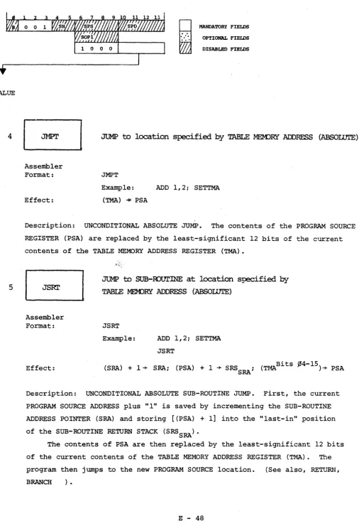
JUMP to location specified by TABLE MEMJRY ADDRESS (ABSOLUrE)
JMPT
Example:
(TMA.) -io' PSA
ADD 1,2; SETTMA
Description: UNCONDITIONAL ABSOLUTE JUMP. The contents of the PROGRAM SOURCE
REGISTER (PSA) are replaced by the least-significant 12 bits of the current
contents of the TABLE MEMORY ADDRESS REGISTER (TMA).
Assembler Format:
Effect:
JUMP to
SUB-murINE
at location specified byTABLE MEK>RY ADDRESS (ABSOWTE)
JSRT
Example: ADD 1,2; SETTMA
JSRT
(SRA) + 1 -+ SRA; (PSA) + 1 + SRS ; (TMABits
.0
4-15)+ PSA SRADescription: UNCONDITIONAL ABSOLUTE SUB-ROUTINE JUMP. First, the current
PROGAAM SOURCE ADDRESS plus "1" is saved by incrementing the SUB-ROUTINE
[image:52.618.39.553.44.785.2]VALUE
6
SET PROGRAM SOURCE ADDRESS (SETPSA)
Assembler Format:
Effect:
1 0 0 0
H
~
MANDATORY FIELDS OPTIONAL FIELDS DISABLED FIELDS
JUMP to location indicated by SWITCH REGISTER,
via PANEL BUS (ABSOLUTE)
JMPP
(SRWBits ~4-l5) +PNLBS + PSA
Description: UNCONDITIONAL ABSOLUTE JUMP. The current contents of the
least-significant 12 bits of the SWITCH REGISTER (SWR) are loaded into the
PROGRAM SOURCE ADDRESS REGISTER (PSA) via the PANEL BUS (PNLBS).
The program then jumps to the new PROGRAM SOURCE location.
WARNING: Propagation delays inherent when
executing JMPP may disallow proper
decoding of certain target
instruc-tions. The perferred alternative
sequence is as follows:
t SWDB; LDTMA
n
VALUE
7
SET PROG~~ SOURCE ADDRESS (SETPSA)
Assembler Format:
Effect:
1 0 0 0
R
Wj
MANDATORY FIELDS OPTIONAL FIELDS DISABLED FIELDS
JUMP to SUB-IDUTINE tx>inted by the SWITCH REGISTER
JSRP
(SRA) + 1 + SRAi (PSA) + 1 + SRSSRAi
(SWRBits ~4-l5) + PNLBS + PSA
Description: UNCONDITIONAL ABSOLUTE SUB-ROUTINE JUMP. First, the current
PROGRAM SOURCE ADDRESS (PSA) plus "1" is "saved" by incrementing the
SUB-ROUTINE ADDRESS POINTER (SRA) by "1" and storing [(PSA) + 1 ] into the
"last-in" position of the SUB-ROUTINE RETURN STACK (SRS SRA).
Then the contents of the PROGRAM SOURCE ADDRESS REGISTER are replaced
by the current contents of the least significant 12 bits of the SWITCH
REGISTER (via the PANEL BUS). The program then jumps to the new PROGRAM
SOURCE location. (See also, RETURN, BRANCH ).
WARNING: Propagation delays inherent when
executing JSRP may disallow proper
decoding of certain target
in-structions. The preferred
alterna-tive sequence is as follows:
t SWDB i LDTMA n
PSEVEN, PSODD AND PS FIELDS
The following instructions available in the PSEVEN and PSODD fields
involve PROGRAM SOURCE partial-word transfers via the PANEL BUS.
Addressing for a given instruction may be RELATIVE or ABSOLUTE. (See
SPEC SUMMARY.) All instructions within these fields require two cycles
to execute and instructions from other fields which reference PNLBS for
addressing or use PNLBS as a transfer-conduit should not be
concurrently specified.
Formats for the various PS partial-words is given below:
Please note the warnings in the HALT, BDBN, BDBZ and JSRA descriptions for WRT the PS, PSEVEN and PSODD instructions.
NOTES
1) When VALUE or TMA is used as an addressing subscript, the least-significant 12 bits are used.
Example:
PS(QO) (VALUE)=PS(QO) (VALUE) (bits 52-63) PS(QO)(TMA)=PS(QO)(TMA)(bits 04-15)
TMA is TMA Register, not the Table Memory Address which may be modified by the FFT bit APSTATUS.
2) PS Quarter 0 is Bits 00 to 15
=
PS(QO)1 16 to 31
=
PS(Ql)2 32 to 47
=
PS(Q2)VALUE
~
1
2
3
PROGRAM SOURCE - EVEN FIELD (PSEVEN)
MANDATORY FIELDS
1 0 0 1
H
Wj
OPTIONAL FIELDS DISABLED FIELDSEJ
Assembler Format:
Effect:
c::J
AssemblerFormat:
Effect:
~
Assembler Format:
Effect:
c:=J
Assembler Format:
Effect:
READ PROGRAM SOORCEQUARI'ER
~
to LITES (ABSOLUTE)RPS~A adr
(PSQ¢ ) -+ PNLBS -+ LITES VALUE
READ PROGRAM SOORCEQUARI'ER 2 . from LITES (ABSOLUTE)
RPS2A adr
Q2
(PS VALUE) -+ PNLBS -+ LITES
RPS~ adr
(PsQ¢ PSA) -+ PNLBS -+ LITES VALUE +
READ PROGRAM SOURCEQUARI'ER 2 to LITES (REIATIVE)
RPS2 adr
Q2
VALUE
5
6 and
7
lJO
11
PROGRA.\1 SOURCE - EVEN FIELD (PSEVEN)
..
.
,.
1 0 0 1
§.
MANDATORY FIELDS OPTIONAL FIELDS DISABLED FIELDS
6
Assembler Format:
Effect:
~
c::J
Assembler Format:
Effect:
c::J
Assembler Format:
Effect:
READ PK>GRAM SOURCEQUARI'ER 2 to LITES
fran the location specified by TABLE MEMJRY ADDRESS
RPS2T
( PsQ2 ) ~ PNLBS ~ LITES TMA
No Operation
WRITE PK>GRAM SOURCEQUARrER yJ from the SWITCHES (ABSOWIE)
WPS¢A adr
(SWR)
~
PNLBS~
PsQ¢VALUE
WRITE PK>GRAM saJlCEQUARIER 2 fran the
SWITCHES (ABSOLUTE)
WPS2A ·adr
VALUE
12
13
14
15
PROGRAM SOURCE - EVEN FIELD (PSEVEN)
G
Assembler Format: Effect:[ ; ]
Assembler Format: Effect:EJ
Assembler Format: Effect:~
Assembler Format:1 0 0 1
~
.
..
...
MANDATORY FIELDS
OPTIONAL FIELDS DISABLED FIELDS
WRITE PROGRAM
SClJRCEQ~ ~
fran theSWI'ICHES (REIATIVE)
wps¢ adr
(SWR) + PNLBS + PsQ¢
VALUE + PSA
WRITE PROGRAM SClJRCEQUARmR 2 fran the
SWI'IaiES (REIATIVE)
WPS2 adr
Q2
(SWR) + PNLBS + PS VALUE + PSA
WRITE PROGRAM SClJRCEQUARI'ER
~
fran theSVr.rrtllES at the location specified by TABLE MEM)RY ADDRESS
WPS¢T
(SWR) + PNLBS + PsQ2 TMA
WRITE PROGRAM SClJRCEQUARrER 2fran the
SWITCHES at the location specified by TABLE MEM:>RY ADDRESS
VALUE
{I
1
2
3
PROGRAM SOURCE - ODD FIELD (PSODD)
MANDATORY FIELDS
..
..
.
OPTIONAL FIELDS1 0 1 0
i·'
DISABLED FIELDSG
Assembler Format:
Effect:
c=J
Assembler Format:
Effect:
c=J
Assembler Format:
Effect:
c:J
AssemblerFormat:
Effect:
RPSlA adr
(opS Q 1 ) -+ PNLBS -+ LITES VALUE
READ PROGPAM SOURCEQUARrER 3 . fran LITES (ABSOwrE)
RPS3A adr
(PsQ3 ) -+ PNLBS -+ LITES VALUE
READ PROGPAM SOURCEQUARrER 1 to LITES (RELATIVE)
RPSI adr
(PsQlVALUE + PSA) -+ PNLBS -+ LITES
READ PROGPAM SOURCEQUARrER 3 to LITES (RELATIVE)
RPS3 adr
Q3
VALUE
4
5
6 and
7
1~
11
PROGRAM SOURCE - ODD FIELD (PSODD)
1 0
B
Assembler Format:
Effect:
~
Assembler Format:
Effect:
~
~
Assembler Format:
Effect:
[;J
MANDATORY FIElDS
i
...
" OPTIONAL FIELDS1 0 DISABLED FIELDS
READ PROGRAM SOtJRCECUARI'ER 1 to LITES fran the
location specified by TABLE MEM)RY AOORESS
RPSIT
Ql
(PS TMA) -+ PNLBS -+ LITES
READ PROGRAMSOURCEQUARl'ER 3 to LITES fran the
. location specified by TABLEMEM)RY ADDRESS
RPS3T.
(PsQ3 ) -+ PNLBS -+ LITES TMA
No Operation
WRITE PROGRAM SOURCECUARI'ER 1 fram the SWI'ICHES (ABSOLtJrE)
WPSIA adr
VALUE
12
13
14
15
PROGRAM SOURCE - ODD FIELD (PSODD)
8
Assembler Format:
Effect:
GJ
Assembler Format:
Effect:
~
Assembler Format:
Effect:
~
Assembler Format:
1 0 1 0
i·'
"
...
MANDATORY FIELDS OPTIONAL FIELDS DISABLED FIELDS
WRITE PROGRAM SOtJOCEQUARrER 1 fran the SWITCHES (RE!IATIVE)
WPSI adr
(SWR) -+ PNLBS -+ PsQl
VALUE + PSA
WRITE ProGRAM SOURCEQUARrER 3 fran the SWITCHES (REIATIVE)
WPS3 adr
Q3
(SWR) -+ PNLBS -+ PS VALUE + PSA
WRITE PROGRAM SOURCEQUARrER 1 fran the SWITCHES
at the location specified by TABLE MEMJRY ADDRESS
WPSIT
(SWR) -+ PNLBS -+.PsQ1 TMA
WRITE ProGRAM SOURCEQUARrER 3 fran the SWITCHES
at the location specified by TABLE MEM:>RY .ADDRESS
VALUE
PROGRAM SOURCE FIELD CPS)
Assembler Format:
Effect:
1 0
MANDATORY FIELDS
~
..
OPTIONAL FIELDS1 1 DISABLED FIELDS
READ PRJGRAM
~
HALF to DATA PAD BUS (ABSOLUTE)RPSLA adr
(PSLH ) -+ DB VALUE
Description: PROGRAM SOURCE(LEFT HALF) (PS LH]=PS bits 00-31]), as
addressed by the least-significant 12 bits contained in the VALUE field (Instruction Word bits 48-63]), is enabled onto DATA PAD BUS (DB).
The transfer is executed in the following manner: