Abstract— Safety of a nuclear power plant and its related systems are the first key issue to assure experts and the public of the safe operation of the plant. The AP1000 reactor is provided with passive safety systems which require no operator actions due to utilizing only natural forces such as gravity, natural circulation and compressed gas to achieve the safety function.
In this paper the core damage frequency due to Small Break LOCA Initiating Event has been presented and besides that, the reliability analysis of the passive core cooling system has been evaluated by the aid of RAT (Risk Assessment Tool) which was developed in the Nuclear Safety Center of Shiraz University. Multiple Greek letter Logic (MGL) method is used for the evaluation of CCF of high redundancy safety systems.
The results show that the contribution of the SB LOCA in the final core damage frequency of AP1000 is decreased due to passive safety systems usage and human independent functions.
The results are useful in core melt down frequency evaluation and final safety analysis report of an advanced nuclear power plant.
Index Terms— AP1000, Probabilistic Reliability Method, Multiple Greek Letters, Passive Core Cooling System, Small Break LOCA
I. INTRODUCTION
The AP1000 is a two-loop pressurized water reactor (PWR) with a gross power rating of 3415 megawatt thermal (MWt) and a nominal net electrical output of 1117 megawatt electric (MWe). The AP1000, with a 157-fuel- assembly core, is ideal for the new base load generation.
The AP1000 passive safety systems require no operator actions to mitigate design-basis accidents. These systems use only natural forces such as gravity, natural circulation, and compressed gas to achieve their safety function. No pumps, fans, diesels, chillers, or other active machinery are used, except for a few simple valves that automatically align and actuate the passive safety systems. The passive safety systems do not require the large network of active safety support systems (ac power, diesels, HVAC, pumped cooling water) that are needed in typical nuclear plants. As a result, in the case of the AP1000, those active support systems must no longer be safety class, and they are either simplified or
Manuscript received September 9, 2009.
Shahabedin Kamyab is with the School of Engineering, Shiraz University 71348-51154, Shiraz, Iran. Tel./fax:+987116473474 E-mail address:
Mohammadreza Nematollahi is with the School of Engineering, Shiraz University 71348-51154, Shiraz, Iran.
Mohammadali Kamyab is with the School of Engineering, Shiraz University 71348-51154, Shiraz, Iran.
Abdosamad Jafari is with the School of Engineering, Shiraz University 71348-51154, Shiraz, Iran.
eliminated.
The AP1000 passive core cooling system (PXS Fig 1) performs safety injection and reactor coolant makeup from the following sources:
Core makeup tanks (CMTs): Accumulators:
In-containment Refueling Water Storage Tank (IRWST):
In-containment passive long-term recirculation means Passive Residual Heat Removal (PRHR) utilizing Passive Residual Heat Removal Heat Exchanger (PRHR HX):
Automatic Depressurization System (ADS): Internal IEs: Three major types of IEs are identified in AP1000:
1. Loss-of-Coolant Accidents (LOCAs) (11 categories)
2. Transients (12 categories)
3. Anticipated Transient without Scram (ATWS) (3 categories)
Small Break LOCA (SB-LOCA) events are characterized by breaks in the RCS with sizes between 3/8 and 2 inch diameters. These events consist of RCS breaks having a size greater than those producing leakage that can be made up by the chemical and volume control system and less than that required to depressurize the PRHR sufficiently, or a stage 1, 2, 3 ADS valve is not needed before a stage 4 ADS valve can automatically open. The Small LOCA event results in a reactor trip and safety injection signal (S-signal) causing CMT actuation and reactor coolant pumps trip, passive RHR actuation, and containment isolation.
Common-Cause Analysis: Dependent and common-cause failures are significant contributors to the unavailability of safety systems in commercial nuclear power plants. They defeat the redundancy incorporated into the design to improve the availability of some plant functions, such as coolant injection
Multiple Greek Letter is one of the most common methods that has been used for CCF analysis in systems with degree of redundancies higher than 2(an extension of β factor model). For a system of “m” redundant components and for each given root cause, “m” different parameters are defined. For simplification purposes, only the first three parameters are generally used. The first three parameters of the Multiple-Greek Letter model are:
β = conditional probability common cause of a component failure will be shared by one or more additionalcomponents,
Evaluating the Reliability of AP1000 Passive
Core Cooling Systems with Risk Assessment
Tool
Sh. Kamyab and M. Nematollahi and M. Kamyab and A. Jafari
γ = conditional probability common cause of a component failure that is shared by one or more components will be shared by two or more components additional to the first,
δ = common cause of a component failure that is shared by two or more components will be shared by three or more components additional to the first.
Equation I is used to calculate the probability of a basic event (Qk Where 1 < k < m) involving the failure of 4 or fewer
specific components.
1
,….
1, , , … , 0
II. MODELING METHODOLOGY:
ETs describe and organize the event sequences. Core Damage State (CDS) Event Trees associated with Small Break LOCA have been constructed in the RAT special graphical interface of ET.
Some sections of the small LOCA Event Tree which was constructed in RAT have been given in Fig 2 (only the end tail parts of it have been shown here). Event tree node titles are given below, from left to the right in the corresponding ET.
I. SLOCA II. RTRIP III. CMT IV. PRHR
V. ADS(F-P) (Full or Partial) VI. ACC
VII. NRHR VIII. IRWST
IX. CIS X. RECIRC XI. CHR
The descriptions of the above list (wherever is necessary) are given below:
SLOCA – Small LOCA Event Occurs: The frequency of SB
LOCA event due to industrial data is 5.00E-04(events/year).
RTRIP – Reactor Trip Occurs
CMT – Reactor Coolant System Pumps Trip and Core
Makeup Tanks: CMT injection requires the reactor coolant
pumps be tripped to reduce the pressure in the reactor coolant system cold leg. The CMTs are designed to actuate on an S-signal, low-2 pressurizer level, or high hot leg temperature with low steam generator level. Failure of this top event is the failure to actuate at least one core makeup tank, either automatically or manually, or failure to trip the reactor coolant pumps.
PRHR – Passive Residual Heat Removal System: The PRHR
system consists of a heat exchanger and inlet and outlet lines connected to the RCS. Operation of the PRHR system is
initiated (valves opened) upon receipt of any of the following signals: low steam generator level narrow range with low startup feed water flow to any steam generator, low steam generator level wide range, high hot leg temperature and CMT or ADS actuation.
ADS-(F or P) – (Full or Partial) Reactor Coolant System
Depressurization: When the reactor cannot be cooled at high
pressure, the depressurization system should be actuated to permit injection either by normal RHR or by gravity. Full reactor coolant system depressurization is the reduction of the system pressure to a value such that gravity injection can be initiated. Partial depressurization is defined as the reduction of the reactor coolant system pressure to a value so that injection into the reactor coolant system can be achieved with the normal residual heat removal pumps, but not by gravity. ADS actuation can be obtained either manually by the operator or automatically on the core makeup tank low water level.
The following depressurization line configurations (i.e., control and associated isolation valve open) are required in The PRA models:
a. Full RCS depressurization
b. Partial RCS depressurization
The details about depressurization mechanisms are given below:
a. For full RCS depressurization, the following conditions
can be assumed, depending on whether the previous nodes succeeded or failed.
i. For small LOCA, including RCS leak and tube ruptures, with CMT injection and with PRHR available to reduce the RCS pressure below the stage 4 automatic pressure interlock set point:
3 out of 4 lines of ADS stage 4
ii. For small LOCA, including RCS leak and tube ruptures, with CMT injection but without PRHR: 3 out of 4 lines of ADS stage 4, with 1 out of 4 lines of stage 1 OR 2 OR 3 to reduce RCS pressure to below the stage 4 automatic pressure interlock set point (manual actuation of stage 4 does not require the other stages)
iii. For small LOCA, including RCS leak and tube ruptures, without CMT injection:
3 out of 4 lines of ADS stage 4, manually actuated.
b. For partial RCS depressurization, the following
i. For small LOCA, including RCS leak and tube ruptures, with CMT injection and with PRHR available to reduce the RCS pressure to below the stage 4 automatic pressure interlock set point: 2 out of 4 lines of stages 1 OR 2 OR 3 OR out of 4 lines of stage 4, automatic or manual actuations ii. For small LOCA, including RCS leak and tube
ruptures, with CMT injection but without PRHR: 2 out of 4 lines of stages 1 OR 2 OR 3 out of 4 lines of stage 4
iii. For small LOCA, including RCS leak and tube ruptures, without CMT injection but with PRHR available:
2 out of 4 lines of stages 1 OR 2 OR 3 out of 4 lines of stage 4, manually actuated
iv. For small LOCA, including RCS leak and tube ruptures, without CMT injection and without PRHR:
2 out of 4 lines of stages 1 OR 2 OR 3 out of 4 lines of stage 4, manually actuated
ACC – Accumulators: whenever the RCS pressure goes
below the nitrogen pressure of 700 psig, actuation of accumulators is a diverse mean for providing cooling water injection by pressurized nitrogen into the RCS, through the SI lines into the PRV.
Failure of this function is the failure of both accumulators to inject water into the RPV, given the successful depressurization to below the accumulator nitrogen pressure.
NRHR – Normal Residual Heat Removal in Injection Mode:
The normal RHR system is configured to take suction from the cask loading pit or the IRWST and discharge to the SI line. The normal RHR system, aligned in this mode with one out of two pumps operating, can also accomplish long-term core cooling if the recirculation function is successful.
IRWST – Gravity Injection: once full depressurization of the
RCS and either CMT or accumulator injection has occurred, gravity injection can be established. This is achieved by permitting the water from the IRWST to flow through one of the two gravity injection lines into the SI lines. A drop in the CMT level automatically actuates the IRWST injection. Failure of this function is the failure of both gravity injection lines to open.
CIS – Containment Isolation Occurs
RECIRC – Water Recirculation to RPV from the Sump
Occurs: The recirculation of water from the containment
sump to the RPV is necessary for long-term core cooling. If
the CIS is successful, one-of-four lines to the two recirculation paths is sufficient for success. If the CIS is not successful, a more stringent success criterion of two-of-four lines to the recirculation paths is required.
CHR – Containment cooling is established: following events
that cause a significant increase in containment pressure and temperature such as a LOCA and main steam line break accident inside containment, the removal of thermal energy from the containment atmosphere to the environment via the steel containment vessel is necessary. If the RECIRC is successful, one-of-three possible paths of water supply lines will be activated in response to a high-2 containment pressure signal or a high containment temperature signal.
A list of all top events of the current ET under investigation should be prepared and the mission time must be defined, based on the ET analysis. As a general rule, the mission time for the systems preventing core damage is 24 hours. A success criteria summary table for each top event has been completed to develop the corresponding FTs for each listed top event.
Fig 3 represents the CMT subsystem FT to inject water into the RCS following a SB LOCA, which was constructed by RAT’s FT interface (as an example).
The next step in the PRA evaluation is to quantify the developed FTs to obtain cut sets. In this way, the FT which has been presented in Fig 3 has the failure probability of 1.1*10-4.
For the components identified by the common-cause analyst that have a potential importance to the total risk, a detailed analysis is performed, as can be seen in the following example.
The failure of both the core makeup tanks occurs when all of the four air-operated valves fail to open. The common-cause failure parameters for a group of four air-operated valves are:
β = 7.8E-2, γ = 0.93, δ = 0.77.
The common-cause multipliers obtained using equations for Qk(m) are:
Q2/QT = 1.8E-3, Q3/QT = 5.6E-3, Q4/QT = 5.6E-2.
The independent failure is: QT = 1.1E-3/d.
The combinations of two-out-of-four and three-out-of-four valves are assessed to have a negligible contribution with respect to the global common-cause failure. Therefore, the common cause of check valves to open, leading to the failure of both core makeup tanks, is evaluated as:
CCX-AV-LA = (Q4/QT)* QT
Its value is: CCX-AV-LA = 6.2E - 5/d.
III. RESULTS AND DISCUSSION
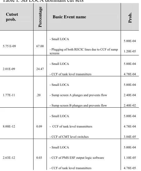
SB LOCA Event Tree has been evaluated by RAT (Fig 2). Table I shows the frequency of some of the dominant cut sets in SB LOCA evaluation (some of them have not been given in Table I because of their low frequency of occurrence).
oth sm bee val tot pas dec of occ CD pla red to dep wit red typ coo A req str lev it LO the of occ int A rec val tra un mo A be com sys pro con wit Ea the Ev
It is seen that her cut sets hav mall contributio
Evaluating the en found that th lue of 1.81E-0 tal CDF whic ssive safety creases the CD In addition, Ta SB LOCA E currence frequ DF. The result ays a significa duction. Theref SB LOCA CD pressurization, th a contributio To consider dundant system pical set of C oling sub-syste An examinati quired to show ainers are the vel of low plan further. Open OCA events, an
e feed and blee IRWST strain cur due to com ternal events w After that, Com circulation high
lves which is ansient events
detected, the ore than 1600 t As an importan
noted that mmon-cause f stem failure, co ocess should b nservatism mig Table IV show th Small Break ach FT failure em) can be use vent Tree evalu
except the firs ve a negligible on to CDF.
e SB LOCA E he resulting CD 8, which contr ch is 2.47E-07
systems impr DFs caused by S able II represen Event Tree w uencies and th ts show that r ant role in ac fore its failure DF, i.e. 3.5 pe , which let the on of 2.12 perc the CCF effe ms, Table III h Common Caus
ems.
ion of basic that the CCFs most significa nt damage frequ
ing of these v nd after ADS ed operation is ners or contain mmon cause and would increase m
mmon cause fa h-pressure squi essential and . Should suc CDF from int times.
nt point in the if the com failures to be ore damage, or be reevaluated ght be removed ws the evaluatio
k LOCA Event probability (o d as a top even uation.
t three SB LOC e failure proba Event Tree usin
DF from Small ributes only 7.5 7. This shows roves plant SB LOCA. nts the most do which lead to
heir contributio recirculation af ccident mitiga has a significa ercent. The ne e long term cor cent.
fect on the p has been presen
ses among the event importa of IRWST reci ant in maintain uency, or poten
valves is need operation in tr s performed. S
nment sump s d go undetected more than 6000 ailure of IRWS
ib valves i.e. o vital after mo ch a failure
ternal events w PRA quantific mmon-cause m
dominant cont r serious releas d to determin d.
on of FTs which t Tree top even or the summat nt (the nodes) f
CA cut sets th ability and very
ng RAT, it ha l LOCA has th 5 percent to th s that utilizing
reliability and ominant cut set
a CDS, thei on to the tota fter SB LOCA ation and CDF ant contribution ext is full ADS re cooling star performance o nted showing e passive cor ance results i irculation sump ning the curren
ntially reducing ded after mos ransients, when
hould plugging creen plugging d, the CDF from
0 times. ST injection and opening of thes
ost LOCA and occur and go would increas cation, it should method cause
tributors to th se, the data and
e whether any h are associated nts:
tion of a set o frequency in th he y as he he g d ts ir al A F n S rt of a re is p nt g st n g g m d e d o e d es he d y d of he Fig 1.Pass
Fig 2. Sm
Fig 2. CM
IV. FIG
sive core cooli
mall Break LOC
MT Fault Tree F
URESANDT
ng system [6]
CA Event Tree
Following a SB ABLES
(end-tail part)
Table I. SB LOCA dominant cut sets
Cutset prob.
P
erc
e
n
tag
e
Basic Event name
Pr
o
b
.
5.75 E-09 67.00
- Small LOCA
- Plugging of both RECIC lines due to CCF of sump screens
5.00E-04
1.20E-05
2.01E-09 24.47 - Small LOCA
- CCF of tank level transmitters
5.00E-04
4.78E-04
1.77E-11 .20 - Small LOCA
- Sump screen A plunges and prevents flow
- Sump screen B plunges and prevents flow
5.00E-04
2.40E-04
2.40E-02
8.00E-12 0.09 - Small LOCA
- CCF of tank level transmitters
- CCF of CMT level switches
5.00E-04
4.78E-04
3.84E-05
2.63E-12 0.03 - Small LOCA
- CCF of PMS ESF output logic software
- CCF of tank level transmitters
5.00E-04
1.10E-05
4.78E-05
Table II. Internal IEs at power dominant cut sets
Table III. CCF typical data set
[image:5.612.321.550.61.283.2]
Table IV. SB LOCA top events FTs
FT description Failure
probability
AC1A
Failure of the accumulator subsystem to inject water into the reactor coolant system given a loss-of-coolant accident due to a break in one of the accumulator lines or direct vessel injection lines
3.9E-03
ADTLT
ADS, manually actuated, fail partial RCS depressurization, given a small LOCA.
1.9E-03
PRL
Failure of PRHR to remove heat from reactor coolant system following small loss of coolant accidents.
1.4E-04
IW2ABM
Failure of IRWST / gravity injection lines to deliver water from IRWST to the RCS following a transient or LOCA (manually actuation only)
1.1E-04
CM2SL
Failure of the CMT subsystem water to the reactor coolant system following a small LOCA, main steam line break SG tube rupture, or PRHR system tube rupture.
0.5E-04
Frequency Sequence
co
n
tr
ib
u
te
%
Sequence description
7.44E-09 3.5
SB LOCA IE occurs Success of CMT& RCP TRIP Success of PRHR system
Success of full ADS depressurization Success of normal RHR in injection mode Success of two of two IRWST injection lines Success of CIS& pre-existing containment opening
Failure of recirculation
5.11E-09 2.12
SB LOCA IE occurs Success of CMT& RCP TRIP Success of PRHR system
Failure of full ADS depressurization Success of partial ADS depressurization Failure of normal RHR in injection mode
3.30E-09 1.37
SB LOCA IE occurs Success of CMT& RCP TRIP Success of PRHR system
Success of full ADS depressurization Failure of normal RHR in injection mode Failure of two of two IRWST injection lines
Common
cause Description
Fa
ilu
r
e
p
r
obab
il
ity (E
-04
)
ADX-MV-GO
Common cause failure of the stages 1, 2
and 3 motor-operated valves 7.48
PXX-AV-LA1
Common cause of IRWST gutter AOVs to
close 0.96
ACX-CV-GO
Common cause failure of accumulator
check valves to open 0.51
V. CONCLUSION
SB-LOCA Event Tree has been constructed by RAT ET’s interface; its CDF frequency has been estimated to be 1.81E-08. It means that employing redundant and diverse passive safety systems and omitting the complexity and human based functions reduces the contribution of core damage frequency due to SB LOCA down to 7.5 percent which is less than other typical PWRs. Furthermore this value lies in the fourth place among highest CDSs IEs (the first three CDSs are SI lines break, Large Break LOCA and spurious ADS IEs).
CCF basic events have been considered. Beta factor method leads to conservative results for systems of redundancies higher than 3. Therefore, MGL method has been used to evaluate CCF probabilities in such redundant subsystems which gives more precise and more reliable results. As expected fewer CCFs have been experienced in AP1000. It seems that utilizing of passive safety systems has reduced the CCFs because of diminishing the numerous sources of common causes like complexity, the same electrical power actuation in share and operator actions requirements.
The results also show that RAT software which has been developed in Nuclear Safety Center of Shiraz University is reliable software and its results can be useful in PRA evaluations, with enough degree of assurance.
ABBRIVIATIONS
ACC : Accumulator
ADS : Automatic Depressurization System CCF : Common Course Failure
CCS : Containment Cooling System CDF : Core Damage Frequency CMT : Core Makeup Tank IE : Initiating Event
IRWST : In-containment Water Storage Tank MOV : Motor Operated Valve
PMS : Protection and Monitoring System PRA : Probabilistic Risk Assessment PRHR : Passive Residual Heat Removal RAT : Risk Assessment Tool
RCS : Reactor Coolant System RECIRC : Recirculation
RPV : Reactor Pressure Vessel SB-LOC
A
: Steam Generator
SG : Safety Injection SI : Safety Injection
REFERENCES
[1] Advanced Light Water Reactor Requirements Document, Volume
III, Appendix A to Chapter 1, “PRA Key Assumptions and
Groundrules,” Revisions 5 and 6, (1993).
[2] A.Majdara and M.Nematollahi, "Development and Application of Risk Assessment", Reliability Engineering & Systems Safety, 93, 1130-1137, (2008)
[3] M. Modarres, Risk Analysis in Engineering: Probabilistic
Techniques, Tools and Trends, CRC Press, (2006)
[4] E. E. Lewis, Nuclear Power Reactor Safety, Wiley- Interscience
publication, (1977).
[5] AP1000 Probabilistic Risk Assessment, Westinghouse Electric
Company, (2007)
[6] AP1000 brochure, Westinghouse Electrical Company, (2006)
[7] NUREG/ CR-2300 “PRA Procedure Guide,” Volume 1, ANS and
IEEE, (1983)
[8] M. Rausand and A. Hoyland, System Reliability Theory, John
Wiley $ Sons, Canada, (2004)
[9] J.Moubray, Reliability- Centered Maintenance, Industrial Press
Inc., New York, (1997)
[10] NUREG/ CR-6268 “Common-Cause Failure Database and
Analysis System: Event Data Collection, Classification, and
Coding”, REV.I ,NRC, (2007)
[11] A.Majdara, Design and Implementation of a Risk Monitor and Its
Application for a Typical Research Reactor, M.Sc.Thesis in