Abstract — Many robotics problems do not take dynamics of
actuators into account in the formulation of the control solution. The fallacy is in assuming that desired forces/torques can be instantaneously and accurately generated. In practice actuator dynamics may be unknown and can have significant transient effect on the overall results. This paper presents a Model Reference Adaptive Controller for the actuators of a robotic biped walker. The actuators learn and produce the torque required for a walking cycle presented in the form of a torque reference model. The actuators of the biped adapt themselves to match with the desired torque reference model with the aid of Lyapunov stability criterion. This control scheme for the biped robot is simulated on a sagittal plane. The results verify the MRAC scheme for the actuators.
Keywords- Model Reference Adaptive Control, Biped walker,
Actuator Dynamics.
I. INTRODUCTION
Biped walking dynamics is highly non-linear, has many degrees of freedom and requires developing highly complicated model to describe its walking behavior. There are number of novel approaches emerging in the field of biped walking to address this complicated control mechanism. Existing biped walking methods [3]-[5], give precise stability control for walking bipeds. However these methods require highly precise biped walking dynamics. In the recent years, biped walking through imitation has been a promising approach, since it avoids developing complex kinematics of the human walking trajectory and gives the biped a human like walking behavior. These methods combine the conventional control schemes to develop the walking mechanism for the bipeds. Examples include, imitation based on intelligent control methods like genetic algorithm [6], [4], fuzzy logic [7] , neural network approach [8], and other methods such as adaptation of biped locomotion [5], learning to walk through imitation [8] and reinforcement learning [4], [7]. But these methods cannot readily adapt their behavior to the changes in the dynamics of the process and the character of the disturbances [2]. Therefore there are adaptive control approaches [10]-[12].
Manuscript received on July 15th, 2009.
Pavan K. Vempaty (corresponding author, [email protected]), Ka C. Cheok and Robert N. K. Loh are with the Department of Electrical and Computer Engineering, Oakland University, Rochester, MI 48326 USA.
To address the problem of poorly known actuator dynamic characteristics and unpredictable variations of a biped system, we propose a Lyapunov based model reference adaptive control system (MRAC) method for the biped walking control. In MRAC the presence of the reference
model specifies the plants desired performance. The plant (biped actuators) adapts itself with the reference system (desired signals to the actuators). In this paper, reference system signals are represented by torques derived from a simulated biped walking control parameters [1]. Alternatively, we can also capture the walking control parameters from human walking movements using motion capturing devices. Once we have the walking control parameters either derived or captured, the reference model will be implemented based on this control data. The plant will then adapt itself to provided control data (reference model). Lyapunov’s stability criterion is applied in feedback for tuning the parameters to make the error between the reference and the plant tends to zero. Through this scheme, a robot can learn its behavior through its reference models.
II. PROBLEM DESCRIPTION A. Objective
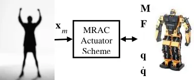
[image:1.612.321.513.564.644.2]Consider the objective of controlling a biped robot so that it imitates the movements of a person. Due to uncertainty associated with nonlinear actuator dynamics and unknown parameters, an adaptive control scheme will be used to achieve the objective. Fig.1. shows the concept where a model references adaptive control (MRAC) scheme is proposed for a biped robot to imitate human movement.
Fig. 1 Biped Robot, Its Actuators and Human Movements The study presented in this paper deals with the formulation, simulation and experimental aspects of the MRAC actuator scheme.
Model Reference Adaptive Control for
Actuators of a Biped Robot Locomotion
Pavan K. Vempaty, Ka C. Cheok, and Robert N. K. Loh
MRAC Actuator Scheme m
x
M F
Equations for describing the dynamics of a biped robot have been introduced in [1], and can be summarized as follows.
( )
(
, , ,)
q =bA q q&& q q M F& (1)
where qis the generalized coordinates of the robot, Mthe moments/torques applied to the joints in the robot and F the reaction forces at the contact of the robot’s feet and ground. Many literatures assume that M can be readily generated without considering dynamics of actuators. As an example, if a set of desired torques are calculated asMd, then it would assume that M=Md and applied directly as inputs to the robot. However, this is not a valid assumption since in practice the moments M will be generated by actuators. We model the moment as states xa=Mas follows:
( , , )
a= a a+ a a+ a ext
x& A x B u d q q& τ (2) where uaare inputs of actuators and d q qa( , ,& τext) represents disturbance torques to the actuators due to robot movements. τextis an external disturbance torque. It is
assumed that we can monitor torques xa by measuring the currents in the actuators.
The movements of a person is represented by the states r. The control objective can therefore be expressed as the desire to drive a part of q to r.
B. Adaptive Control Approach
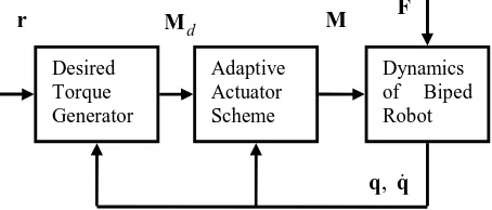
[image:2.612.82.309.520.617.2]The problem here is that we have to deal with unknowns and uncertainties in the dynamics and parameters of the systems described by (1) & (2). An MRAC scheme based on Lyapunov stability synthesis is proposed for dealing with the issue. Fig. 2.shows the adaptation scheme:
Fig. 2 MRAC scheme for the biped walker. III. PRELIMINARIES
A. Dynamics of Walking Biped
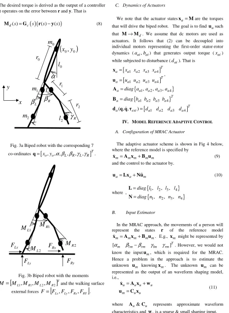
The bipedal model in this project has five links connected by pin joints as shown in the figure 3.a. One link represents the upper body and two links are for each lower
limb. The biped has two hip joints, two knee joints and two ankles at the tips of the lower limbs. There is an actuator located at each join and all of the joints are considered rotating only in the sagittal plane. As the system can move freely in the x-y-plane and contains five links, it has seven degrees of freedom. The corresponding seven coordinates are selected according to fig. 3a.
[
xo,yo, ,α β β γ γ
L, R, L, R]
T=
q (3)
The coordinates
(
x y
o,
o)
fix the position of the center of mass of the torso, and the rest of the coordinates describe the joint angles. The link lengths are denoted as(
l
0,
l
1,
l
2)
and masses as
(
m
0,
m
1,
m
2)
. The centers of mass of the links are located at the distances(
r
0,
r
1,
r
2)
from the corresponding joints.The model is actuated with four moments two of them acting between the torso and both thighs and two at the knee joints, which is shown in fig. 3.b.
M
=
[
M
L1,
M
R1,
M
L2,
M
R2]
T (4) The walking surface is modeled using external forces that affect both leg tips shown in fig. 3b.
F
=
[
F
Lx,
F
Ly,
F
Rx,
F
RY]
(5)When the leg should touch the ground, the corresponding forces are switched on to support the leg. As the leg rises, the forces are zeroed.
Using Lagrangian mechanics, the dynamic equations for the biped system can be derived as shown in (1) where
7 7
)
(
q
XA
∈
ℜ
is the inertia matrix and(
)
7 1,
,
,
q
M
F
Xq
b
&
∈
ℜ
is a vector containing the right hand sides of the seven partial differential equations. The closed form formulas for both A and b are presented in [1].B. Computation of Desired Moments
The desired human movement is represented by
[
α
mβ
l mβ
rmγ
lmγ
rm]T= −
r
(6) An output y is constructed from the biped feedback info q as
y
=
[
α
β
l−
β
rγ
lγ
r]
T=
C
yq
(7) DesiredTorque Generator
Adaptive Actuator Scheme
Dynamics of Biped Robot
r Md M F
,
The desired torque is derived as the output of a controller that operates on the error between r and y. That is
[image:3.612.93.559.63.700.2]Md( )s =Gc
( )(
s r( )s −y( )s)
(8)Fig. 3a Biped robot with the corresponding 7 co-ordinates q=
[
xo,yo, ,α β β γ γ
L, R, L, R]
T.Fig. 3b Biped robot with the moments
[
]
TR L R
L
M
M
M
M
M
=
1,
1,
2,
2 and the walking surfaceexternal forces
F
=
[
F
Lx,
F
Ly,
F
Rx,
F
RY]
.C. Dynamics of Actuators
We note that the actuator statesxa=Mare the torques that will drive the biped robot. The goal is to find uasuch that M→Md. We assume that dc motors are used as actuators. It follows that (2) can be decoupled into individual motors representing the first-order stator-rotor dynamics (aai,bai) that generates output torque (xai) while subjected to disturbance (dai). That is
[
]
[
]
1 2 3 4
1 2 3 4
T
a a a a a
T
a a a a a
x x x x
u u u u
= =
x
u
,
{
}
{
}
1 2 3 4
1 2 3 4
, , ,
a a a a a
T
a a a a a
diag a a a a
diag b b b b
= =
A
B
[
1 2 3 4]
( , , ) T
a ext = da da da da d q q& τ
IV. MODEL REFERENCE ADAPTIVE CONTROL A. Configuration of MRAC Actuator
The adaptive actuator scheme is shown in Fig 4 below, where the reference model is specified by
m = m m+ m m
x& A x B u (9) and the control to the actuator by.
ˆ
a= a+ m
u Lx Nu (10)
where ,
{
}
{
}
1 2 3 4
1 2 3 4
, , , , , ,
diag l l l l
diag n n n n
= =
L
N
B. Input Estimator
In the MRAC approach, the movements of a person will represent the states r of the reference model
m = m m+ m m
x& A x B u . E.g., xm might be represented by
[
α
mβ
l m−β
rmγ
lmγ
rm]T. However, we would notknow the inputum, which is required for the MRAC. Hence a problem in the approach is to estimate the unknown um knowingxm. The unknown um can be represented as the output of an waveform shaping model, i.e.,
u u u u
m u u
= +
=
x A x w
u C x &
(11)
where Au&Cu represents approximate waveform characteristics and wuis a sparse & small shaping input. 2
m
1m
0
m
1
l
0
l
2
l
2
r
1r
0r
α
L
β
β
RR
γ
(
x
0, y
0)
x
1 L
M
M
R12 R
M
2L
M
F
RxLx
F
Ly
F
F
RyFig. 4 The MRAC with the input predictor.
E.g., (1) is a so-called
αβ
model if 0 10 0
u
=
A &
[
1 0]
u =
C . The reference model and shaping model can be augmented as
mu mu mu mu u
m mu mu
= +
=
x A x B w
x C x &
(12)
where , ,
0
m m m u
mu mu m
u u
= = =
x A B C 0
x A B
x A I
& Cmu =
[
I 0]
; 0&I are null and identity matrix, respectively, of appropriate dimensions. An estimate of the of um can be found using an observer of the form[
]
[
]
ˆ ˆ ˆ
ˆ ˆ
mu mu mu mu m mu mu
m m mu
= + −
=
x A x K x C x
u 0 C x &
(13)
ˆm
u is used as the input to the MRAC as shown in (10)
C. MRAC
The adaptation algorithm in the MRAC adjusts the gains L and N based on Lyapunov stability design. In design, we assume that the disturbances are negligible. It follows from
the Lyapunov design that the gains
{
1, 2, 3, 4}
diag l l l l
=
L &N=diag n
{
1, n2, n3, n4}
are adjusted according to1
(
)
1
ˆ
(
)
i i di ai ai
ai i
i i di ai mi
ai i
l
p M
x
x
b q
n
p M
x
u
b r
=
−
= −
−
(14)
where we have used the notation
[
]
[
]
1 2 3 4
1 2 3 4
ˆ ˆ ˆ ˆ ˆ
T
d d d d d
T
m m m m m
m m m m
u u u u
= =
M
u
(15)
D. Analysis of Error Dynamics
In the ensuing analysis we will assume that the uˆm
generated by the input observer converges to the unknown m
u . Define the errors e between the actuator torque a=
x M and the desired torque xm=Md as
a m
= −
e x x (16) It can be shown that
[
]
[
]
ˆ ( , , )m a a m a
a m m a ext
= + − −
+ − +
e A e A B L A x
B N B u d q q τ
&
& (17)
E. Lyapunov Stability Analysis
Define a candidate for a Lyapunov function as
(
) (
)
(
) (
)
T
T
a a m a a m
T
a m a m
v trace trace = + − − − − + − − e Pe
A B L A Q A B L A
B N B R B N B
(18)
where P=PT >0, Q=QT >0 and R=RT >0 are positive definite matrices. The
(
)
(
)
(
)
(
)
( )
(
)
2 2 T T Ta a m a
T
a m a
v trace trace = + + − − − + −
e Pe e Pe
A B L A Q B L
B N B R B N & & & & & (19)
(
)
(
(
)
)
(
)
(
)
(
( )
)
(
)
2 ( , , ) 2
ˆ 2
T T T T
m m m a ext
T T
a a m a a
T T
a m am a
trace trace = + + + − − + − + − +
e PA A P e e A d q q τ
A B L A Pex Q B L
B N B Peu R B N &
& &
Reference Model Input
Predictor
N
L
∑ Actuator Dynamics
Adaptation Mechanism
( , , )
a ext d q q& τ
a = x M m
u
m = d
x M
ˆm
u
From inspection, we choose 1
1
ˆ
T
a a
T
a am
−
−
= = −
B L Q Pex
B N R Peu &
& (20)
so that
2
( , ,
)
T T T T
m m m a ext
v
&
=
e
PA
+
A P e
+
e A d q q
&
τ
(21)We note that expansion of (20) leads to the (14). We next choose an S=ST >0 and solve P from
PA
m+
A P
Tm= −
S
(22)We arrive at
2
( , ,
)
T T T
m a ext
v
&
= −
e Se
+
e A d q q
&
τ
(23)
where
v
&
is negative under the assumption that2
( , ,
)
T T T
m a ext
>
e Se
e A d q q
&
τ
(24)or when error is more significant than the effect of disturbance. Hence we claim the overall dynamic system comprising of (17) and (20) has a candidate function that satisfies the Lyapunov stability criterion under condition (24).
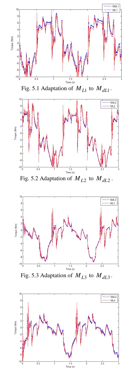
V. SIMULATION RESULTS A. Description of Simulation Test
The proposed control scheme for the 5 link biped model consisting of (1)-(10) and (13)-(14) is simulated. The biped is excited with a walking cycle that is manually developed and provided as the desire human movement r. This walking cycle is repeated for the subsequent steps for every 1.5 seconds. Biped walking is tested for 3seconds. The desired torques Md =
[
MdL1 MdL2 MdL3MdL4]
T are generated using Eq. (8). Fig.5. shows the output[
]
TL L L
L
M
M
M
M
M
=
1 2 3 4 of the adaptive [image:5.612.78.466.54.689.2]actuator scheme adapting itself with the reference input
M
d. The first interval, 0 to 1.5 (s), of Fig. 5.1 to Fig 5.4 shows the adapted torquesM
oscillates and adjusts to converge to the desired torquesM
d. The second interval, 1.5 to 3.0 (s), shows convergence settling smoothly to desired reference. Fig.5.5 illustrates the result of the biped walking behavior from the adapted torques M. Fig. 5.6 plots the height of the biped torso.Fig. 5.1 Adaptation of ML1 to MdL1.
Fig. 5.2 Adaptation of ML2 to MdL2.
Fig. 5.3 Adaptation of ML3 to MdL3.
[image:5.612.327.523.63.652.2]Fig. 5.5 A 2-step simulation of biped walking on the sagittal plane with the Y-axis representing the height of the biped
[image:6.612.116.276.161.313.2]torso
y
o.Fig. 5.6 Height of the biped torso
y
o.Equation (2) includes disturbance torques d q qa( , ,& τext)
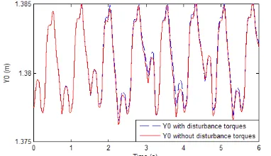
[image:6.612.101.292.433.543.2]which represents torque feedback and other external moments. This causes the dynamics of the actuator to vary. In the simulation, we disturbed the biped walker by introducing two sharp impulses as shown in Fig. 5.7. Fig. 5.8 shows that the biped recovers from the impact due to the external disturbance.
Fig. 5.7 Height of the biped torso with and without disturbance torques d q qa( , ,& τext), simulated over 6 (s).
Fig. 5.8 Simulated external disturbance to (2), at t=0.65(s) and t=1.77(s).
VI. CONCLUSIONS
In this paper, we presented an MRAC technique to ensure that the actuators faithfully produce desired torques necessary for a walking robot. An observer was used to predict an anticipated state of the desired torque, thus cause the adaptive actuators to anticipate motion torques. We provided a proof to show that the MRAC scheme results in a stable system in the sense of Lyapunov when errors between the desired and actuator torques are significant. Simulation results verify that the system is robust when tested with various parameters and unknown coefficients. We plan to implement the MRAC scheme for an actual humanoid biped robot to follow the gait of a person in future work.
REFERENCES
[1] Olli Haavisto, Heikki Hyotyniemi, “Simulation tool of biped walking robot model,” M.S. Thesis, Helsinki University of Technology, Espoo, Finland, 2004.
[2] Karl J. Astrom, Bjorn Wittenmark, “Model-Reference Adaptive Systems,” in Adaptive Control, 2nd ed., Boston: Addison-Wesley Longman, 1994, pp. 206-235.
[3] Shuuji Kajita, Fumio Kanehiro, Kenji Kaneko, Kiyoshi Fujiwara, Kensuke Harada, Kazuhito Yokoi and Hirohisa Hirukawa, “Biped walking pattern generation by using preview control of zero-moment point,” Proc. of IEEE Int. Conf. on Robotics & Automation, vol. 2, pp: 1620-1626, 2003.
[4] Seungsuk Ha, Youngjoon Han, Hernsoo Hahn., “Adaptive gait pattern generation of biped robot based on human’s gait pattern analysis,” Proceedings of the International Journals of Mechanical System Science and Engineering, vol. 1, no. 2, pp. 80-85, 2008. [5] Jun Nakanishi, Jun Morimoto, Gen Endo, Gordon Cheng, Stefen
Schaal, Mitsuo Kawato., “ Learning from demonstration and adaptation of biped locomotion with dynamical movement primitives,” Proceedings of the 4th IEEE /RAS International
Conference on Humanoid Robotics, vol. 2, pp. 925-940, 2004. [6] Kristen Wolff, Peter Nordin, “Evolutionary learning from first
principles of biped walking on a simulated humanoid robot,” Proceedings of the business and Industry Symposium of the Simulation Technologies Conference ASTC’03, pp. 31-36, March 30th – April 3rd 2003.
[7] Changjiu Zhou, Qingchun Meng, “Dynamic balance of a biped robot using fuzzy reinforcement learning agents,” Fuzzy sets and systems archive, vol. 134, issue 1, pp 169-187, 2003.
[8] Poramate Manoonpong, Tao Geng, Toman Kulvicius, Bernd Porr, Florentin Worgotter., “Adaptive, Fast Walking in a Biped robot under neuronal control and learning,” PLos Computational Biology, 2007.
[9] Rawichote Chalodnan, David B. Grimes, Rajesh P. N. Rao., “Learning to walk through imitation,” Proceedings to the 20th International Joint Conference on Artificial Intelligence, pp. 2084-2090, 2007.
[10] Jerry Pratt, Chee-Meng Chew, Ann Torres, Peter Dilworth, Gill Pratt., “Virtual model control: an intuitive approach for bipedal locomotion,” Proceedings of the International Journal of Robotics Research, vol. 20, no. 2, pp. 129-143, 2001.
[11] Eugen Bobasu, Dan Popescu., “Adaptive nonlinear control algorithms of robotic manipulators,” Proceedings of the 7th WSEAS
International Conference on Automation & Information, pp. 83-88, 2006.