Characterization of Mechanical Properties of
Beryllium Copper alloy by Structural Strength
Analysis on Universal Joint using FEM Solver
ANSYS Structural
Sandhya1, Prof. K.K. Jain2 1
M.Tech Student, 1, 2 Department of Mechanical Engineering, Shri Ram Institute of Technology Jabalpur M.P.
Abstract: In this dissertation research article we aimed to get the knowledge of mechanical behavior of copper alloy material beryllium copper using a 3D model of universal joint. For this purpose we have studied so many authors to get the parameters which affect the performance of universal joint. We found that factors and parameters such as material of universal joint, Construction and size of the universal joint, Mechanical properties of universal joint, Optimization methods for universal joint system, Innovative design of universal joint are the parameters which can be optimized for getting better results of structural performance enhancement of universal joint. Following the review process we modeled a 3d geometry of universal joint in CATIA V5 and performed structural analysis on ANSYS 14.0. we found out by solution of the analysis that beryllium copper is more suitable for manufacturing of universal joint since we got less total deformation for beryllium copper when compared with the conventional material of universal joint i.e. structural steel . The values of stresses and strains were found to be optimum as well. These all contributed to increase the structural performance of universal joint by using alloy material beryllium copper. Keywords: Mechanical characterization, Alloy materials, Structural Analysis, Universal joint, ANSYS structural.
I. INTRODUCTION
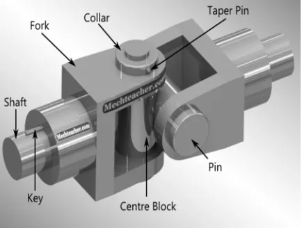
A universal joint is a positive, mechanical connection between rotating shafts, which are usually not parallel, but intersecting. They are used to transmit motion, power, or both [1]. The simplest and most common type is called the Cardan joint or Hooke joint. It is shown in Figure 1.1. It consists of two yokes, one on each shaft, connected by a cross-shaped intermediate member called the spider. The angle between the two shafts is called the operating angle. It Is generally, but n01 necessarily, constant during operation. Good design practice calls for low operating angles, often less than 25°, depending on the application [3]. Independent of this guideline, mechanical interference in the construction of Cardan joints limits the operating angle to a maximum (often about 37½°), depending on its proportions [4].
The two fork ends are assembled co-axially with respect to the centre block. The pins are assembled into the holes provided in the fork end [4]. They are held in position by means of a collar and a collar pin [5].
[image:1.612.199.416.546.710.2]II. LITERATURE SURVEY
After studying various research articles of different authors we have found out these parameters and factors which can be further optimized for improving the structural strength of universal joint.
A. Material of Construction
Geun-Yeon Kim, Seung-Ho Han and Kwon-Hee Lee [6], Studied and changed the existing material made of GCD45 to Al6082M and recommended the lightweight design of the universal joint as the optimal design technique to be installed in small cars. Six shape design variables were selected for the optimization of the universal joint and the criteria relevant to stiffness and durability were considered as the design requirements during the optimization process. The Meta model-based optimization method that uses the kriging interpolation method as the optimization technique was applied. The result shows that all constraints for stiffness and durability are satisfied using A16082M, while reducing the weight of the universal joint by 60% compared to that of the existing GCD450.
B. Optimization Methods
Ms. Nilesha U. Patil, Mrs. Rupali S. Sewane and Mr. Kashinath H. Munde [7], Studied and calculated the stresses in Universal joint and optimized the model of Universal joint for its weight reduction. Modeling of the universal joint was done using 3D software. Here CATIA V5 had been used for modeling. The simulation part was carried out using the Analysis software, ANSYS. With the Boundary constrains and the twisting moment applied, the universal joint was analyzed. Then using Topology optimization material was removed. Again, analysis was done on an optimized model for stresses and deformation and optimized values. The maximum stress and deformation values were in the acceptable limits.
Mahesh P. Sharma, et.al. [8], Have done static analysis of steering universal joint. They designed a universal joint which accommodates dual caliper mountings for increasing braking efficiency & reducing a stopping distance of a vehicle. CAD modal of universal joint was prepared in CREO2.0. Static analysis was done in ANSYS WORKBENCH by constraining the universal joint, applying loads of braking torque on caliper mounting, longitudinal reaction due to traction, vertical reaction due to vehicle weight and steering reaction. They have also done shape optimization of same universal joint and saved material resource. Shape optimization of universal joint was done using ANSYS WORKBENCH making objective function as reducing weight. Shape optimization method used in this study reduced the mass of universal joint by 19.35%. Also factory of safety is between 3 to 4. Maximum stress and displacement were within control. They concluded that the overall weight of the vehicle can be reduced to achieve savings in costs and materials, as well as, improve fuel efficiency and reduce carbon emissions.
Ms.Nilesha U. Patil, et. al. [9], Studied and calculated the stresses and deformation in Universal joint and optimized the model of same Universal joint. They used CATIA V5 for modeling. They aimed to use FEA and Taguchi method to improve the quality of manufactured goods and engineering development of design for studying variation. Taguchi recommends the use of the S/N ratio to measure the quality characteristics deviating from the desired values analysis. Regardless of the category of the quality characteristic, a greater S/N ratio corresponds to better quality characteristics. It was predicted that Taguchi method is a good method for optimization of various machining parameters as it reduces the number of experiments. Stress, strain and deformation were within acceptable limits. Pankaj Dulani and S. A. K. Jilani [10], Studied the problem of the failure of the universal joint pin in any mechanism for general due to crushing, tearing and shearing. The aim of the present paper was to study calculate the stresses in Universal joint using analytical method. The study focused on the optimization of design parameters kept in mind for the universal joint pin. The Neural Network Tool, a nontraditional global optimization technique had been used as the solution methodology for its inherent advantages. Optimal results so obtained were compared with remodeled universal joint pin with stress minimizing effect considered as a key factor. After remodeling of the universal joint using the predicted optimized parameters obtained by neural network the model was used to generate the value of stress which was compared with the neural network result in order to prove that optimized model is better as compared to the previously selected four models.
C. Stress Concentration
Dinesh Shinde And Kanak Kalita [12], Studied stresses on tractor trailer during acceleration (tensile) and during deceleration (compressive). Forces acting over the joint were calculated by considering Newton’s Second Law of motion. Pin was considered separately for the analysis and finite element analysis is done on it. They concluded that Numerical value of tangential force and von mises stresses acting on the universal joint were maximum in case of deceleration.
Abhishek Mandal & Utkarsh Sharma [13], conducted static structural analysis on a universal coupling using advanced computer aided engineering software and study the various stresses and strains developed in the joint. Results concluded that the fork pin experiences the maximum compressive stresses and strains as referenced earlier. Also stated that region where the fork and the fork pin makes contact experiences generally higher compressive stress and bending stresses. Also analyzed that stress concentration in the collar and pin due to the presence of notch that leads to frequent wearing out of the pin which causes the shaft to wobble unnecessarily which reduces the mechanical efficiency of the transmission system. This leads to failure of the transmission system.
D. Geometrical Dimensions and Mechanical Construction
Suraj Yadav, et.al. [14], Have done modeling and analysis of universal joint under a certain conditions. Modeling and analysis of a universal joint was performed by using 3D software CATIA & Finite Element Analysis (FEA) respectively. The commercial finite element package ANSYS version 15 was used for the solution of problem.
They concluded that 30C8 material having maximum permissible stress is 400MPa and Maximum stresses developed in universal joint are 201MPa. So design is safe. They also concluded that pin of 25 mm diameter can sustain load of 50 KN without a failure. Shankar Majhi & Shaheen Beg Mughal [15], analyzed universal joint pin stresses during its operation. Force acting on the fork and pin were calculated by the theoretical study and analytical method. Subjected to high stresses in pin were studied by using CATIA V5 and finite element method. According to their theoretical study, calculation and F.E.A results were similar on 50 mm diameter at 60 KN. They concluded that when stress on pin increases, bending increases but when we increase the pin diameter it will wear maximum stress on that force.
Ravindra S. Dharpure and Prof D. M. Mate [16], Reviewed the problem of the failure of the universal joint pin in a railway coupling due to shearing as per the defined conditions and analysis the present steel material can be substituted with a proper elastic material. The presently for the problem of shear failure of the pin alternatively plastic universal joint pin that will accept bending fatigue, thereby reducing pin failure can be used.
The pin made of a plastic material having a flexibility that will allow it to bend and return to its original shape and to also be self- lubricating. Further, the pin eliminates rust and corrosion and produces a low coefficient of friction between the pin and the coupler body and universal joint, thus enhancing opening and closing of the universal joint by reducing rotational resistance, thereby promoting safety. It has been known that steel pins, either at the time of installation or after service, can cause a “lazy universal joint”, i.e., a universal joint that will not open all the way on decoupling.
Sourav Das, Vishvendra Bartaria & Prashant Pandey [17], studied for calculating the stresses in Universal joint using analytical method. Material of the universal joint is considered as mild steel grade 30C8, ANSYS software was run and the stress contour, displacement contour, strain energy contour were obtained. It was proposed that instead of mild steel pin we can also use high strength high modulus steel pin that can further enhance the capacity to withstand higher loads. The shape of the universal joint can be changed for improved properties. Further study in this direction can made by using various directions of the pin and the capacity to withstand load.
E. Finite Element Analysis Meshing Method
Sangamesh B. Herakal, Ranganath Avadhani and Dr.S.Chakradhar Goud [18], Studied to calculate the stresses in Universal joint using analytical method. They concentrated on which type of meshing is preferable for components. universal joint was modeled by making use of CATIA, later on that model was imported in HYPERMESH and carried out both mesh those were hexahedral and tetra mesh. The model was solved by using Abacus software.
F. Weight Reduction and life Cycle
Dhananjay S Kolekar, abhay M. Kalje and Swapnil S Kulkarni [19], Have done finite element analysis of the universal joint to find the stress and displacement. For modeling of the component PRO-E software was used. Pre-processing work like meshing and analysis work was carried out in HYPERWORKS software. The geometry was modified using topology and free size optimization which enabled to reduce stress level marginally well below the yield limit. They got a percent mass reduction of about 7%. The developed stresses for this model were within the acceptable limits which showed the safety of model.
Pilla. Anitha and V. Hari Shankar [20], focused on optimization of steering universal joint targeting reducing weight as objective function with required strength, frequency and stiffness. They used optimization which refers to different cases in the shape optimization and also the topology optimization.
Nishant Vibhav Saxena And Dr. Rohit Rajvaidya [21], proposed the modification of one of the material that changed cast iron by a composite polymer material. The proposed system had many advantages over other system such as making the device, simpler and having maximum safety and is eco friendly. Composite polymers are characterized by a high flexibility material.
III. GEOMETRY
The figure shown below is a 3d model of universal joint made with -
A. Case1) Spring Steel
B. Case2) Beryllium copper
Fig.3.1) 3D Geometry of universal joint
IV. MESHING
The figure shown below shows the meshing of universal joint geometry made with
A. Case1) Spring Steel
B. Case2) Beryllium copper
V. SOLVER SETUP The following figures show the setup for solution in the Ansys 14.0.
A. Case1) Spring Steel
B. Case2) Beryllium copper
The figure shown below shows the fixed support applied at bottom end.
Fig.5.1) Fixed support at one end
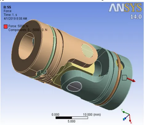
The figure shown below shows the application of 1200N tensile force at the top end
Fig.5.2) Tensile force at other end
Table 5.1
Details Of Material Properties properties→
material name↓
Density ( g/cm3)
Modulus of Elasticity
(GPa) Poisson ratio Tensile Strength(MPa)
Spring Steel 7.85 200 0.3 460
[image:5.612.193.420.162.353.2] [image:5.612.189.423.393.596.2]TABLE 5.2
Details Of Loads And Supports
Object Name Fixed Support Force
State Fully Defined
Scope
Scoping Method Geometry Selection
Geometry 1 Face
Definition
Type Fixed Support Force
Suppressed No
Define By Components
Coordinate System Global Coordinate System
X Component 0. N (ramped)
Y Component 5000 N (ramped)
Z Component 0. N (ramped)
VI. RESULTS
The figures shown below are the contour graph of results of analysis for equivalent stress (Von -Mises) and total deformation
A. Case1) Spring Steel
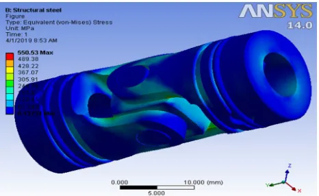
Fig.6.1) Equivalent stress for spring steel
[image:6.612.191.424.343.486.2] [image:6.612.191.421.520.714.2]B. Case2) Beryllium copper
Fig.6.3) Equivalent stress for Beryllium copper
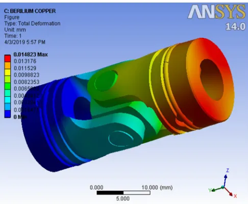
[image:7.612.182.431.89.276.2]Fig.6.4) Total Deformation for beryllium copper
TABLE 6.1
Solution Results Of All The Materials For Equivalent Stress Von Mises And Total Deformation
Name of material→
solution↓ Structural Steel Beryllium Copper
Equivalent stress (MPa) 550.53 518.38
Total deformation(mm) 0.02261 0.014823
VII. CONCLUSION
[image:7.612.185.428.305.505.2]REFERENCES
[1] Ms. Nilesha Patil, Mrs. Sayli M.Sable and Mr. Kashinath Munde, “Static Structural Analysis of Universal joint”, International Journal of Advanced Technology in Engineering and Science, vol 4, issue 12, december 2016.
[2] Prof. Swati Datey, Amit A. Rangari, Adarsh A. Dongre, Kunal A. Paraskar & Sanket V. Lidbe, “Analysis of Universal joint used in Mahindra 575 DL”, IJARIIE-ISSN(O)-2395-4396, Vol-3 Issue-2 2017.
[3] Nipun Kumar, Dr. Gian Bhushan and Dr. Pankaj Chandna, “Analysis of Universal joint of Various Materials using CAE Tools”, International Journal of Engineering Technology, Management and Applied Sciences, Volume 5, Issue 1, January 2017.
[4] Kodali. Vikas and Kandula. Deepthi, “Analysis of Serial Pinned Joints in Composite Materials”, International Journal of Computational Engineering Research, Vol, 04, Issue, 10, October– 2014.
[5] Shaik.John Bhasha and Hari Sankar Vanka, “Modeling and Analysis of Universal joint”, International Journal & Magazine of Engineering, Technology, Management and Research, Volume No: 2 (2015), Issue No: 11 (November).
[6] Geun-Yeon Kim, Seung-Ho Han and Kwon-Hee Lee, “Structural Optimization of a universal joint with Consideration of Stiffness and Durability Requirements”, The Scientific World Journal, 2014.
[7] Ms. Nilesha U. Patil, Mrs. Rupali S. Sewane and Mr. Kashinath H. Munde, “Optimization of Universal joint by using FEA”, International Conference on Ideas, Impact and Innovation in Mechanical Engineering), Volume: 5 Issue: 6, 2017.
[8] Mahesh P. Sharma, Denish S. Mevawala, Harsh Joshi and Devendra A. Patel, “Static Analysis of Steering universal joint and Its Shape Optimization”, IOSR Journal of Mechanical and Civil Engineering, PP 34-38, 2014.
[9] Ms.Nilesha U. Patil, Prof.P.L.Deotale, Prof. S.P.Chaphalkar, A.M.Kamble & Ms.K.M.Dalvi5, “ Application Of Taguchi Method For Optimization Of Universal joint” International Journal of Recent Trends in Engineering & Research (IJRTER) ,Volume 03, Issue 11; November - 2017 .
[10] Pankaj Dulani and S. A. K. Jilani, “Diameter and Spiral Thickness Optimization of Universal joint Using Neural Network”, International Journal of Science and Research, Volume 5 Issue 2, February 2016.
[11] Miss. Yogini .V. Deore ,Prof. J.R.Mahajan K, Mr. Vinay Patil & Mr. Balasaheb Ugale, “ A Static Structural Analysis Of Universal joint”, International Journal Of Advanced Research In Engineering & Management (Ijarem) ,Pp. 10-22, Vol. 03, Issue 04, 2017.
[12] Dinesh Shinde And Kanak Kalita, “FE Analysis Of Universal joint Pin Used in Tractor Trailer”, ARPN Journal Of Engineering And Applied Sciences, Vol. 10, No. 5, March 2015.
[13] Abhishek Mandal & Utkarsh Sharma, “Static Structural Analysis of Universal Joint to Study the Various Stresses and Strains Developed in Power Transmission Systems”, International Journal of Engineering Research & Technology, Vol. 5 Issue 03, March-2016.
[14] Suraj Yadav, Sanket Benade, Sushil Angchekar, Vaibhav Dhokle and Prof. Rakesh Kolhapure, “Design And Analysis Of Universal joint By Using FEA”,Technical Research Organization India,Volume-4, Issue-6, 2017.
[15] Shankar Majhi & Shaheen Beg Mughal, “Modeling and analysis of universal joint used in tractor”, International Research Journal of Engineering and Technology, Volume: 04 Issue: 07, July -2017.
[16] Ravindra S. Dharpure and Prof D. M. Mate, “Study and Analysis of Pin of Universal joint in Train”, Journal of Emerging Technologies and Innovative Research, Volume 1 Issue 3.
[17] Sourav Das, Vishvendra Bartaria & Prashant Pandey, “Analysis of Universal joint Of 30C8 Steel For Automobile Application”, International Journal Of Engineering Research & Technology, Vol. 3 Issue 1, January – 2014.
[18] Sangamesh B. Herakal, Ranganath Avadhani, Dr.S.Chakradhar Goud, “Structural Static Analysis Of Universal joint”, International Journal Of Engineering Research And General Science, Volume 4, Issue 2, March-April, 2016.
[19] Dhananjay S Kolekar, abhay M. Kalje, swapnil S Kulkarni, “Design, Development And Structural Analysis Of Universal Joint”, International Journal Of Advanced Engineering Research And Studies, Vol 4, issue 4, July-September, 2015/09-12.
[20] Pilla. Anitha and V. Hari Shankar, “Design And Topology Optimization Of A Steering Universal joint Using FEA”, International Journal of Scientific and Research Publications, Volume 6, Issue 11, November 2016.