To Study the Rebound Hammer Test for
Non-Destructive Testing of Structure
Prof. A. R. Gupta
1, Mr. Amit G. Kungrani
21, 2Department of Civil Engg, COET
, Akola
, SGB Amravati UniversityAbstract: Concrete compressive strength is one of the most important concrete requirements that can be used to decide if the concrete is structurally acceptable or not. Compressive strength of concrete depends on age of concrete, moisture content, surface carbonation etc. There are several methods used for this purpose, out of all NDT methods, the Rebound hammer test check the compressive strength of concrete. The present study is done to check the structural compressive strength of concrete structure. Rebound hammer becomes very useful for predicting the service life of the structures and to find out structural compressive strength analysis.
Keywords:Visual Inspection, Rebound Hammer Test, Compressive Strength Analysis.
I. INTRODUCTION
A. Aim
To find out structural compressive strength analysis of a college building using Non-Destructive Test i.e. Rebound hammer test.
B. Objectives
1) To study concept and process of NDT.
2) To study in detail about Rebound Hammer Test.
3) To analysis and determine compressive strength of college building.
4) To categories the structure on the basis of structure.
5) To review the result and review for variation in reading
C. Scope
To study compressive strength analysis of various RCC component like column, slab and beam of college building using rebound hammer test.
D. Need
The strength of new concrete is affected by many factors such as type of cement, type of Aggregate, Water cement ratio, curing, environmental condition etc. Besides this the control exercised during construction also contribute a lot to achieve the desired strength. The present system of checking slump and testing cubes, to assess the strength of concrete, in structure under construction are not sufficient as the actual strength of the structure depend on many other factors such as proper compaction, effective curing also. If the selection of proper material and compaction is not done then it causes inhomogeneity as well as air voids, which directly affect on strength of structure. considering the above requirement, need of testing of hardened concrete in new structure, is there to assess the actual condition of structures.
II. LITERATUREREVIEW
structure's in-situ strength. In this paper author gave guideline related to visual inspection. Dhananjay Mangrulkar et. al. (4), In this research paper author did a case study of various Non-Destructive Test (NDT) done on a building whose age was 20 years and was located far away from any industrial or chemical plants. Various NDT methods like ultrasonic pulse velocity test, carbonation test, rebound hammer test and half-cell potential test were used to access the quality of structure. These tests were done to find the voids and cracks in the structural elements. The depth of carbonation was checked whether it is less than the cover concrete or not to make sure the reinforcements does not corrode. Finally, based on the results, the structural elements requiring repairs were identified. D. Breysse (5), In this paper has been analyzes why and how nondestructive testing (NDT) measurements can be used in order to assess on site strength of concrete. It is based on (a) an in-depth critical review of existing models; (b) an analysis of experimental data gathered by many authors in laboratory studies as well as on site, (c) the development and analysis of synthetic simulations designed in order to reproduce the main patterns exhibited with real data while better controlling influencing parameters. The key factors influencing the quality of strength estimate are identified. Two NDT techniques (UPV and rebound) are prioritized and many empirical strength-NDT models are analyzed. It is shown that the measurement error has a much larger influence on the quality of estimate than the model error. The key issue of calibration is addressed and a proposal is made in the case of the SonReb combined approach. Jibin Babu and Akhilchandran Bs et. al. (6), In this paper concrete slabs of different dimensions and characteristics are taken and subjected to destructive test by compressive strength testing and non- destructive testing by rebound hammer method the rebound variety will increase because the strength will increase however it's conjointly plagued by variety of parameters like kind of cement, aggregate, surface condition and wet content of the cement. it's conjointly known that rebound indices are indicative of compressive strength of concrete to a restricted depth from the surface. If the concrete in an exceedingly specific member has internal microcracking, flaws or heterogeneousness across the cross-sectional, rebound hammer indices won't indicate a similar. Dr. George Teodoru et. al. (7), In this paper Author presented an existing non-destructive method for the estimation of different properties of concrete, in reinforcement and prestressed concrete structures and the stage of their normalization in national and international norms. Further on it is illustrated the influence of hardening conditions including those of thermal treatment upon the correlation between the ultrasonic pulse velocity and the concrete compressive strength, including the elements of statistical analysis of this correlation, with original contributions concerning the correlation between the coefficients of variation of the measured nondestructive characteristics and the one of compressive strength, obtained by destructive test. Tarun Gehlot, Dr. S. S. Sankhla, Akash Gupta et. al. (8), The investigation reported here is to present study of Calibration Graphs for Non-Destructive Testing Equipment, the Rebound Hammer and to study the quality of the concrete in existing structures. These Rebound Hammer Test were then used to test the quality of the concrete of the various structural elements (columns & beams) of single storied newly under constructed building of TPO office of MBM Engineering College Jodhpur. The use of this method produces results that lie close to the true values when compared with other methods A correlation between rebound number and strength of concrete structure is established, which can be used as well for strength estimation of concrete structures. The method can be extended to test existing structures by taking direct measurements on concrete elements. Istvan Zsigovics et. al. (9). In this paper Author gives an overview on the development of hardness testing of materials. Rebound hardness tester devices and their operating principle – including the impact phenomena – are introduced. Influencing parameters of the rebound index are interpreted. Considerations about variability parameters of rebound hardness and minimum number of repetition of rebound index reading are presented. The main aim of the rebound hammer test is introduced, and regression techniques are described for the relationship between the rebound index and compressive strength of concrete. R. Sri Ravindrajah, Y. H. Loo, C. T. Tam et. al. (10), In this paper Author present the results of an experimental investigation into the relationship of compressive strength to ultrasonic pulse velocity and to rebound number. It has been observed that for the water-cured concrete the strength-pulse velocity relationship is influenced by the use of the recycled aggregate. For the same value of the pulse velocity, the strength of recycled aggregate concrete is higher than that for the natural aggregate concrete. On the other hand, the strength- rebound number relationship is not affected by the aggregate type used. The combined method of pulse velocity and rebound number for strength estimation is also evaluated.
III. CONCEPT ON NON-DESTRUCTIVE TEST
Usually, representative test specimens are cast from the same concrete mix as the larger structural elements. Unfortunately, test specimens are not an exact representation of in-situ concrete, and may be affected by variations in specimen type, size, and curing procedures.
NDT methods are extremely valuable in assessing the condition of structures, such as bridges, buildings, elevated service reservoirs and highways etc. The principal objectives of the non-destructive testing of concrete in situ is to assess one or more of the following properties of structural concrete as below: -
1) In situ strength properties
2) Durability
3) Density
4) Moisture content
5) Elastic properties
The standard life of R.C.C. frame structure is considered to be in the range of 50-60 years approximately depending upon the use and the importance of the structure. But it has been observed that many of the buildings completing just 50% of their life in coastal areas found to be in distressed condition and this needs the evaluation of the strength of the building so that appropriate remedial action can be taken to improve performance of the building depending upon the extent of deterioration of the structure.
Due to explosion, structure is suddenly loaded by way of impact forces. The structure may get heated up under high temperature generated by explosion and burn partially and deform when it is under loads. Visible damage may immediately help to decide for replacement of the member. But an invisible damage, which has distressed the structure, needs assessment for integrity, loss of strength and stability. Assessment through NDT can guide for reuse of the structure.
IV. PROCESS OF NDT
The condition assessment includes the following step:
A. Initial Inspection And Appraisal Or Visual Inspection
Visual testing is probably the most important of all non-destructive tests. It can often provide valuable information to the well-trained eye. Visual features may be related to workmanship, structural serviceability, and material deterioration and it is particularly important that the engineer is able to differentiate between the various signs of distress which may be encountered. A visual inspection helps to plan a strategy to investigate the structure.
B. Review Of Documents
It is necessary to collect relevant data of a building as much as possible through drawings, enquiry, design calculation, soil report (if available), inspection reports, reports of previous investigation, previous repair works, any complaints by the occupants etc. A site visit is essential for data collection. In case the records are not available, an attempt can be made to retrieve some information based on interviews with those who were involved in the design and construction of the building or familiar with contemporary methods and the owners or residents.
C. Detailed Investigation
Detailed investigation includes the following
1) Obtaining the properties of the structural materials used in the building.
2) Determining the type and disposition of reinforcement in reinforced concrete members.
3) Locating deteriorated materials and other defect, and identifying their causes.
As there are many causes for the deterioration of structure, it may be difficult to identify the cause that has led to the deterioration. Moreover, several types of damage, whether they are load related, environment related, or earthquake related, lead to similar sign of deterioration, such as cracking, delamination, discoloration etc. the area of deterioration should be investigated closely.
D. Reporting And Recommendations
After completion of detailed investigation, a report should be given. Recommendation includes whether to go for repair or rehabilitation of the structural member.
Several non-destructive methods are available to predict in-situ characteristics of concrete such as compressive strength, poison’s ratio, modulus of elasticity, modulus of rupture, voiding, honey combing, micro and macro-cracking, loss of cement matrix, and loss of bond to aggregate etc. The most widely used methods are as follows: -
A. Visual inspection, which is an essential precursor to any intended non-destructive test.
B. Half-cell electrical potential method, used to detect the corrosion potential of reinforcing bars in concrete.
C. Schmidt/rebound hammer test, used to evaluate the surface hardness of concrete.
D. Ultrasonic pulse velocity testing, mainly used to measure the sound velocity of the concrete and hence the compressive strength of the concrete.
E. Impact echo testing, used to detect voids, delamination and other anomalies in concrete.
F. Ground penetrating radar or impulse radar testing, used to detect the position of reinforcing bars or stressing ducts.
VI. VISUAL INSPECTION
A. Introduction
Visual inspection is very effective method for evaluation of structure condition. It also helps us in evaluating requirement of maintenance required for the structure as well as tells us the health of the building. It is the first steps in the evaluation of a concrete structure. Visual inspection can provide a wealth of information that may lead to positive identification of the cause of observed distress. Visual inspection has the obvious limitation that only visible surface can be inspected. Internal defects go unnoticed and no quantitative information is obtained about the properties of the concrete
B. Tools And Equipment For Visual Inspection
An engineer carrying out a visual survey should be well equipped with tools to facilitate the inspection. These involve a host of common accessories such as human eye and brain, aided with a note book, proforma, measuring tapes or rulers, markers, thermometers, anemometers and others. Binoculars, telescopes, borescopes and endoscopes or the more expensive fibre scopes may be useful where access is difficult. A crack width microscope or a crack width gauge is useful, while a magnifying glass or portable microscope is handy for close examination. A good camera with the necessary zoom and micro lenses and other accessories, such as polarized filters, facilitates pictorial documentation of defects, and a portable colour chart is helpful in identifying variation in the colour of the concrete.
C. General Procedure Of Visual Inspection
Before any visual test can be made, the engineer must read all relevant structural drawings, plans and elevations to become familiar with the structure. Available documents must also be examined, and these include technical specification, past reports of tests or inspection made, construction records, details of materials used, methods and dates of construction, etc
The survey should be carried out systematically and cover the defects present, the current and past use of the structure, the condition of adjacent structures and environmental condition. All defects must be identified, the degree classified, like those used for fire damaged concrete and, where possible, the causes identified. The distribution and extent of defects need to be clearly recognized. For example, whether the defects are random or appear in a specific pattern and whether the defect is confined to certain locations of members or is present all over the structure. Visual comparison of similar members is particularly valuable as a preliminary to testing to determine the extent of the problems in such cases. A study of similar structures or other structures in the local area constructed with similar materials can also be helpful in providing ‘case study’ evidence, particularly if those other structures vary in age from the one under investigation. There is a need to identify associated or accompanying defects, especially which defect predominates. Segregation or excessive bleeding at shutter joints may reflect problems with the concrete mix, as might plastic shrinkage cracking, whereas honeycombing may be an indication of a low standard of construction workmanship. Lack of structural adequacy may show itself by excessive deflection or flexural cracking and this may frequently be the reason for an in-situ assessment of a structure. Long term creep defections, thermal movements or structural movements may cause distortion of door frames, cracking of windows, or cracking of a structure or its finishes.
Systematic crack mapping is a valuable diagnostic exercise when determining the causes and progression of deterioration. Observation of concrete surface texture and colour variations may be a useful guide to uniformity. Colour change is a widely recognized indicator of the extent of fire damage.
Visual inspection is not confined to the surface but may also include examination of bearings, expansion joints, drainage channels and similar features of a structure. Any misuse of the structure can be identified when compared to the original designed purpose of the structure. An assessment may also need to be made of the environmental conditions to which each part of the structure has been exposed. The wetting and drying frequency and temperature variation that an element is subjected to should be recorded because these factors influence various mechanisms of deterioration in concrete. For example, in marine structures it is important to identify the splash zone. Settlement of surrounding soil or geotechnical failures need to be recorded. Account must also be taken of climatic and other external environmental factors at the location, since factors such as freeze thaw conditions may be of considerable importance when assessing the causes of deterioration. A careful and detailed record of all observations should be made as the inspection proceeds. Drawings can be marked, coloured or shaded to indicate the local severity of each feature. Defects that commonly need recording include:
1) Cracking which can vary widely in nature and style depending on the causative mechanism
2) Surface pitting and spalling
3) Surface staining
4) Differential movements or displacements
5) Variation in algal or vegetative growths
6) Surface voids
7) Honeycombing
8) Bleed marks
9) Constructional and lift joints
10) Exudation of efflorescence
Classification of the degree of damage or condition requires experience and engineering judgement, but guides are available. Where a large structure is to be examined it may be appropriate to produce a plan or a series of plans indicating ‘climate exposure severity to overlay the engineer’s plans of the structure.
VII. REBOUND HAMMER TEST
The rebound hammer is one of the most popular non-destructive testing methods used to investigate concrete. Its popularity is due to its relatively low cost and simple operating procedures. The rebound hammer is also one of the easiest pieces of equipment to misuse; thus, many people do not trust the rebound test results.
A. The Rebound Hammer Method Could Be Used For
1) Assessing the compressive strength of concrete with the help of suitable co-relations between rebound index and compressive strength
2) Assessing the uniformity of the concrete
3) Assessing the quality of concrete in relation to the standard requirements
4) Assessing the quality of one element of concrete in relation to another.
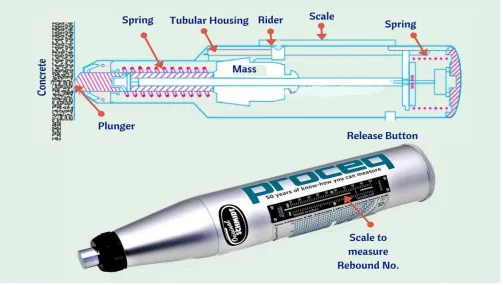
B. Fundamental Principle
When the plunger of rebound hammer is pressed against the surface of the concrete, the spring- controlled mass rebounds and the extent of such rebound depends upon the surface hard- ness of concrete. The surface hardness and therefore the rebound is taken to be related to the compressive strength of the concrete. The rebound is read off along a graduated scale and is designated as the rebound number or rebound index.
C. Equipment For Rebound Hammer Test
The Swiss engineer Helmut Heinrich Waldemar Schmidt reported experiments with a concrete take a look at hammer that measures the surface hardness of concrete (Schmidt, 1950, 1951). The device, called the Helmut Heinrich Waldemar Schmidt Rebound Hammer, measures the rebound of an elastic device mass impacting the free finish of a plunger (steel rod) that\'s control against the concrete surface. The extent of the rebound of this mass is expressed because the rebound variety R. Helmut Heinrich Waldemar Schmidt states in his paper that “the rebound variety R are often thought about as a brand-new quality parameter of the concrete; it characterizes the hardness of the mortar (concrete minus coarse aggregates) at one single location near the surface. The Schmidt rebound hammer is shown in Fig 1. The hammer weighs about 1.8 kg and is suitable for use both in a laboratory and in the field. The main components include the outer body, the plunger, the hammer mass, and the main spring. Other features include a latching mechanism that locks the hammer mass to the plunger rod and a sliding rider to measure the rebound of the hammer mass. The rebound distance is measured on an arbitrary scale marked from 10 to 100. The rebound distance is recorded as a “rebound number” corresponding to the position of the rider on the scale.
Fig. 1: Schmidt Rebound Hammer
D. Checking of Apparatus
It is necessary that the rebound hammer is checked against the testing anvil before commencement of a test to ensure reliable results. The testing anvil should be of steel having Brine11 hardness of about 5000 N/mm2. The supplier/manufacturer of the rebound
hammer should indicate the range of readings on the anvil suitable for different types of rebound hammers.
E. Procedure
For testing, smooth, clean and dry surface is to be selected. If loosely adhering scale is present, this should be rubbed of with a grinding wheel or stone. Rough surfaces resulting from incomplete compaction, loss of grout, spalled or tooled surfaces do not give reliable results and should be avoided. The point of impact should be at least 20 mm away from any edge or shape discontinuity. For taking a measurement, the rebound hammer should be held at right angles to the surface of the concrete member.
Fig. 2: Functioning of Rebound Hammer Test
A higher R-number indicates a greater hardness of the concrete surface. The tests can be performed in horizontal, vertically upward, vertically downward or any intermediate angled positions in relation to the surface.
There is a slide indicator on the outside of the unit that records the distance travelled during the rebound. This indication is known as the rebound number. By pressing the button on the side of the unit, the plunger is then locked in the retracted position and the rebound number (R-number) can be read from the graduated scale (shown in fig3).
Fig. 3: Rebound Value Index
VIII. CONCLUSION
[image:7.595.80.505.407.643.2]IX. ACKNOWLEDGMENT
It gives me an immense pleasure and pride to express my deep sense of gratitude & respect for my teacher and Co-Guide Prof. A. R. GUPTA, College of Engineering and Technology, Babhulgaon, Akola for his evergreen expertise and inspiring guidance during the period of my entire course, which has enlightened me on the finer skills of dealing with synthetic problems.
I would like to express my sincere thanks to Dr. R. M. PHUKE, Guide and HOD, Department of Civil Engineering and all Staff members of department for encouragement and helping me during my project work. We wish to express our warm and sincere thanks to Dr. S. K. Deshmukh, Principal, College of Engineering and Technology, Akola for making all the facilities available in college.
REFERENCES
[1] Kishor Kunal , Namesh Killemsetty, “Study on control of cracks in a Structure through Visual Identification & Inspection”, IOSR Journal of Mechanical and Civil Engineering (IOSR-JMCE) e-ISSN: 2278-1684,p-ISSN: 2320-334X, Volume 11, Issue 5 Ver. VI (Sep-Oct. 2014), PP 64-72.
[2] M. A. D’Cruz, “Visual Defect Survey: Case Study of RCC Structure”, IJLTEMAS Volume III, Issue VI, June 2014. [3] Kaushal Kishore, “Visual Inspection of Concrete Structure”, 35th conference of OUR world in concrete structure
[4] Dhananjay Mangrulkar, Manoj Chauhan, Shubham Kadam, Saurabh Likhare, “Case Study of RCC Structure with the help of Non Destructive Testing” International Research Journal of Engineering and Technology (IRJET) e-ISSN: 0056 Volume: 05 Issue: 03 Mar-2018 www.irjet.net p-ISSN: 2395-0072.
[5] D. Breysse, “Non-destructive evaluation of concrete strength: An historical review and a new perspective by combining NDT methods”, Elsevier – 19th December 2011.
[6] Jibin Babu And Akhilchandran Bs, "Non-Destructive Testing for Building Materials “, Journal of Basic and Applied Engineering ISSN: 2350-0255; Volume 2, Number 15; April - June 2015 Pp. 1251-1254
[7] Dr. George Teodoru, "Romanian Developments in Nondestructive Testing of Concrete Constructions”, BULETINUL AGIR NR. 3/2014.
[8] Tarun Gehlot, Dr. S. S. Sankhla, Akash Gupta, "Study of Concrete Quality Assessment of Structural Elements Using Rebound Hammer Test”, American Journal of Engineering Research (Ajer17.) Volume-5, Issue-8, Pp-192-198.
[9] Istvan Zsigovics, Katalin Szilagyi," Rebound Surface Hardness and Related Properties of Concrete ", Budapest, Open Journal of Civil Engineering 2013. [10] R. Sri ravindrajah, Y. H. Loo, c. T. Tam, "Strength Evaluation of Recycled-Aggregate Concrete by In-Situ Tests", Materials and Structures/ Matoriaux Et