PSpice
®
Optimizer
Cadence PCB Systems Division 13221 SW 68th Parkway, Suite 200 Portland, OR 97223
Copyright © 1985-2000 Cadence Design Systems, Inc. All rights reserved.
Trademarks
Allegro, Ambit, BuildGates, Cadence, Cadence logo, Concept, Diva, Dracula, Gate Ensemble, NC Verilog, OpenBook online documentation library, Orcad, Orcad Capture, PSpice, SourceLink online customer support, SPECCTRA, Spectre, Vampire, Verifault-XL, Verilog, Verilog-XL, and Virtuoso are registered trademarks of Cadence Design Systems, Inc.
Affirma, Assura, Cierto, Envisia, Mercury Plus, Quickturn, Radium, Silicon Ensemble, and SPECCTRAQuest are trademarks of Cadence Design Systems, Inc.
Alanza is a service mark of Cadence Design Systems, Inc.
All other brand and product names mentioned herein are used for identification purposes only and are registered trademarks, trademarks, or service marks of their respective holders.
Part Number 60-30-637
Second edition 31 May 2000
Cadence PCB Systems Division (PSD) offices
PSD main office (Portland) (503) 671-9500
PSD Irvine office (949) 788-6080
PSD Japan office 81-45-682-5770
PSD UK office 44-1256-381-400
PSD customer support (877) 237-4911
PSD web site www.orcad.com
PSD customer support web page www.orcad.com/technical/technical.asp
Contents
Before you begin 13
Welcome . . . 13
How to use this guide . . . 14
Symbols and conventions . . . 14
Related documentation . . . 15
Things you need to know 17
Chapter 1
Chapter overview . . . 17What is the PSpice Optimizer? . . . 18
Designs that you can optimize . . . 19
Designs that you cannot optimize . . . 19
Using the PSpice Optimizer with other Orcad programs . . . 20
Terms you need to understand . . . 21
Primer: How to optimize a design 29
Chapter 2
Chapter overview . . . 29Optimizing a diode biasing circuit—the objective . . . 31
Why use optimization? . . . 32
Phase One: Developing the design . . . 33
The PSpice optimizer advantage . . . 34
Phase Two: Setting up the optimization . . . 35
Defining design parameters . . . 36
Setting up goals and constraints . . . 37
Setting up analyses for each goal and constraint . . . 37
Developing performance measures . . . 38
Defining specifications: goals and constraints . . . 39
Phase Three: Running an optimization . . . 40
Running the PSpice Optimizer . . . 41
Adding a constraint and rerunning the PSpice Optimizer . . . 43
iv
Producing reports . . . 48
Saving results . . . 49
Updating the schematic . . . 49
Using the PSpice Optimizer 51
Chapter 3
Chapter overview . . . 51Starting and loading the PSpice Optimizer . . . 52
Starting the PSpice Optimizer . . . 52
From Capture . . . 52
From the Windows Start menu . . . 53
Changing startup options . . . 53
Loading a different optimization file . . . 54
The PSpice Optimizer Window . . . 55
Specifications area . . . 56
Internal specifications . . . 56
External specifications . . . 57
Parameters area . . . 58
Error gauge area . . . 59
Adding and editing parameters . . . 60
Adding a parameter . . . 60
Selecting a parameter to edit . . . 62
Adding and editing specifications . . . 63
Adding a specification . . . 63
Defining an evaluation for an external specification . . . 67
Selecting a specification to edit . . . 68
Measuring and Optimizing Performance . . . 68
Optimizing Your Design . . . 68
Graphically monitoring progress . . . 70
Exploring the effect of parameter and specification changes . . . 71
Testing performance when changing current values . . . 71
Automatically recalculating performance . . . 72
Manually recalculating performance . . . 73
Ensuring reliable results when tweaking values . . . 74
Excluding parameters and specifications from optimization . . . 75
Testing performance when adding or changing parameters or specifications 75 Saving intermediate values . . . 76
Viewing result summaries . . . 76
Producing optimization reports . . . 76
Viewing the optimization log . . . 78
Finalizing the design . . . 79
Using standard part values . . . 79
Saving results . . . 80
Updating the design . . . 81
Understanding optimization principles and options 83
Chapter 4
Chapter overview . . . 83Goals versus constraints . . . 84
Constrained optimization . . . 85
Types of constraints . . . 86
Feasible and infeasible points . . . 87
Active and inactive constraints . . . 88
Lagrange multipliers . . . 88
Characteristics of functions . . . 89
Global and local minima . . . 90
Starting points . . . 91
Convergence . . . 91
Parameter bounds . . . 92
Derivatives . . . 93
How the PSpice Optimizer estimates derivatives . . . 93
Limitations of derivative data . . . 94
Target value scaling . . . 95
Default options . . . 96
Controlling finite differencing when calculating derivatives (Delta option) . . . 96
Limiting simulation iterations (Max. Iterations option) . . . 97
Specifying a waveform display (Waveform Data File and Display options) 98 Advanced options . . . 99
Controlling cutback (Cutback option) . . . 99
Controlling parameter value changes between iterations (Threshold option) . . . 99
Choosing an optimization method for single goal problems (Least Squares/Minimization options) . . . 101
Tutorial: Optimizing a design (passive terminator) 103
Chapter 5
Tutorial overview . . . 103The passive terminator design . . . 104
Loading the design into Capture . . . 105
Setting part values to expressions . . . 106
vi
Defining the analysis type . . . 108
Running an initial circuit analysis . . . 108
Starting the PSpice Optimizer . . . 109
Viewing the parameter description . . . 110
Defining the goals and constraints . . . 111
Checking that the design will simulate . . . 113
Starting the optimization . . . 113
Changing a goal to a constraint . . . 115
Saving results . . . 115
Tutorial: Exploring design tradeoffs (active filter) 117
Chapter 6
Tutorial overview . . . 117The active filter design . . . 118
The parameters . . . 119
The goals . . . 120
Testing performance . . . 122
Calculating derivatives . . . 122
Tweaking parameters . . . 123
Tweaking goals and constraints . . . 124
Completing optimization . . . 125
Tutorial: Using constrained optimization (MOS amplifier) 127
Chapter 7
Tutorial overview . . . 127The CMOS amplifier design . . . 128
The parameters . . . 129
The evaluations . . . 130
The goals and constraints . . . 132
Setting the method for a single-goal optimization . . . 133
Performing the optimization . . . 134
Tutorial: Fitting model data (bipolar transistor) 137
Chapter 8
Tutorial overview . . . 137Using the PSpice Optimizer to fit data to model parameters . . . 138
The bipolar transistor test case . . . 139
The parameters . . . 140
The analysis . . . 141
The external file of measured data . . . 141
The goals and constraints . . . 142
Monitoring progress with PSpice A/D . . . 144
Error messages 149
Appendix A
Appendix overview . . . 149
Error message descriptions . . . 150
File types used by the PSpice Optimizer 155
Appendix B
Appendix overview . . . 155File and program relationships . . . 156
Measuring performance using information in the circuit file and .PRB file 157 Defining specification criteria in the external data file . . . 158
File type summary . . . 159
Optimizing a netlist-based design 161
Appendix C
Appendix overview . . . 161Optimizing without a schematic . . . 162
Setting up the circuit file . . . 163
Setting up and running the PSpice Optimizer . . . 164
Example: Parameterizing the circuit file . . . 166
Figures
Figure 1 Optimization design flow. . . . 20
Figure 2 Diode biasing design example. . . 31
Figure 3 Design flow for developing the design. . . 33
Figure 4 Design flow for setting up the optimization. . . 35
Figure 5 Design flow for running an optimization. . . . 40
Figure 6 PSpice Optimizer automatic optimization process. . . . 42
Figure 7 Optimization results for the diode design example. . . 43
Figure 8 Results after adding the power constraint. . . . 45
Figure 9 Results after changing the constraint type. . . . 47
Figure 10 Report summary for the diode optimization. . . . 48
Figure 11 Updated diode schematic. . . . 49
Figure 12 The PSpice Optimizer window. . . . 55
Figure 13 Example of a specification box. . . . 56
Figure 14 Example of a parameter box. . . 58
Figure 15 Sample format for an external specification. . . . 65
Figure 16 Sample excerpt from a report. . . . 77
Figure 17 Sample excerpt from a Log file. . . . 78
Figure 18 Sample derivative data. . . 78
Figure 19 Resistive terminator circuit. . . . 84
Figure 20 Global and local minima of a function. . . . 90
Figure 21 Hypothetical function. . . . 94
Figure 22 Hypothetical data glitch . . . 100
Figure 23 Resistive terminator circuit. . . . 104
Figure 24 Schematic for the terminator Example, TERM.DSN. . . . 105
Figure 25 Optimization results for the passive terminator example. . . . 114
Figure 26 Schematic for the active filter example, BPF.DSN. . . 119
Figure 27 Optimized values for the active filter example. . . . 125
Figure 28 Schematic for CMOS amplifier example, M2.DSN. . . . 128
Figure 29 Updated performance values for the amplifier example. . . 134
Figure 30 Optimized values for the amplifier example. . . 135
Tables
Table 1 Optimization problems. . . 21
Table 2 Valid Operators and Functions for PSpice Optimizer Expressions. . . . . 27
Table 3 Edit parameter dialog box controls. . . . 61
Table 4 Edit specification dialog box controls. . . . 64
Table 1 Error message descriptions. . . . 150
Before you begin
Welcome
Orcad family products offer a total solution for your core design tasks: schematic- and VHDL-based design entry; FPGA and CPLD design synthesis; digital, analog, and mixed-signal simulation; and printed circuit board layout. What's more, Orcad family products are a suite of
applications built around an engineer's design flow—not just a collection of independently developed point tools. PSpice Optimizer is just one element in our total solution design flow.
PSpice Optimizer is a circuit optimization program that improves the performance of analog and mixed
How to use this guide
This guide is designed so you can quickly find the information you need to use PSpice Optimizer. To help you learn and use PSpice Optimizer efficiently, this manual is separated into the following chapters:
• Chapter 1 - Things you need to know
• Chapter 2 - Primer: How to optimize a design
• Chapter 3 - Using the PSpice Optimizer
• Chapter 4 - Understanding optimization principles and options
• Chapter 5-8 - Tutorials
Symbols and conventions
Our printed documentation uses a few special symbols and conventions.
Notation Examples Description
C+r Press C+r. Means to hold down the C key while
pressing r.
A, f, o From the File menu, choose Open (A, f,
o).
Means that you have two options. You can use the mouse to choose the Open command from the File menu, or you can press each of the keys in
parentheses in order: first A, then f, then o.
Monospace font In the Part Name text box, type PARAM. Text that you type is shown in monospace font. In the example, you type the characters P, A, R, A, and
M.
UPPERCASE In Capture, open CLIPPERA.DSN. Path and filenames are shown in
uppercase. In the example, you open the design file named CLIPPERA.DSN. Italics In Capture, save design_name.DSN. Information that you are to provide is
Related documentation
In addition to this guide, you can find technical product information in the online book, and our technical web site, as well as in other books. The table below describes the types of technical documentation provided with PSpice Optimizer.
This documentation component . . . Provides this . . .
This guide—
PSpice Optimizer User’s Guide
A comprehensive guide for understanding and using the features available in PSpice Optimizer.
Orcad family customer support at www.orcad.com/technical/technical.asp
An Internet-based support service available to customers with current support options. A few of the technical solutions within the customer support area are:
• The Knowledge Base, which is a searchable database containing thousands of articles on topics ranging from schematic design entry and VHDL-based PLD design to PCB layout methodologies. It also contains answers to frequently asked questions.
• The Knowledge Exchange, which enables you to share information and ideas with other users and with our technical experts in a real-time online forum. You can submit issues or questions for open discussion, search the Knowledge Exchange for information, or send email to another participant for one-on-one communication. A list of new postings will appear each time you visit the Knowledge Exchange, providing you with a quick update of what's been discussed since your last visit. • The Technical Library, which contains online customer
support information that you can search through by category or product. You can find product manuals, product literature, technical notes, articles, samples, books, and other technical information. Additionally, technical information can be obtained through SourceLink, which is an online customer support information service for users of Cadence software other than Capture, Component Information System (CIS), Express, Layout, or PSpice.
• The Support Connection, which allows you to choose to either view and update existing incidents, or create new incidents. The information is delivered directly to us via our internal database. This service is only available to customers with current maintenance or Extended Support Options (ESOs) in the United States and Canada.
• The Live Connection, which enables you to open access to your computer to a Customer Support person, who can then view your actions on your computer monitor as you demonstrate the problem you're having. Live Connection's two-way transmission can also let you view the actions on the Customer Support person's computer monitor, as he or she demonstrates a method or procedure to help you solve your problem. To participate in Live Connection, you need to contact a Customer Support person, in order to obtain a support number to grant you access to the Live Connection site, and to set up a time to “meet online” using Live Connection.
Things you need to know
1
Chapter overview
This chapter introduces the purpose and function of the PSpice Optimizer, the optimization process, and related terms.
• What is the PSpice Optimizer? on page 1-18 describes optimizer capabilities and the criteria designs must meet for successful optimization.
• Using the PSpice Optimizer with other Orcad programs on page 1-20 presents the high-level design flow for optimization and how other Orcad programs are integrated into each design phase.
What is the PSpice Optimizer?
The Orcad PSpice Optimizer is a circuit optimization program that improves the performance of analog and mixed analog/digital circuits.
Run optimizations
The PSpice Optimizer performs iterative simulations, while adjusting the values of design parameters until performance goals, subject to specified constraints, are nearly or exactly met. Constraints can include simple bounds on parameter values and nonlinear functions. The PSpice Optimizer also computes Lagrange multipliers that provide information on the cost of each constraint on the solution.Explore performance tradeoffs
When you enter new values for design parameters, the PSpice Optimizer provides graphical feedback showing performance. You can also tweak goal and constraint values to examine changes to parameter values.Designs that you can optimize
A design that you can optimize must meet the following criteria:
• It works; that is, it simulates with PSpice to completion and behaves as intended.
• One or more of its components have a variable value, and each value that is varied relates to an intended performance goal.
• An algorithm exists to measure its performance as a function of the variable value.
If you can visualize which factors should be adjusted to improve performance, and how you would manually step through the optimization process (even though the computations might seem unwieldy), then the design is a good candidate for the PSpice Optimizer.
Designs that you cannot optimize
You cannot use the PSpice Optimizer to:
• Create a working design. This especially applies when you begin with a design that is far from meeting specifications.
• Optimize a design in which the circuit has several states where a small change in a parameter value causes a change of state. For example: A flip-flop is on
for some parameter value, and off for a slightly different value.
Using the PSpice Optimizer with
other Orcad programs
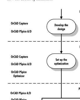
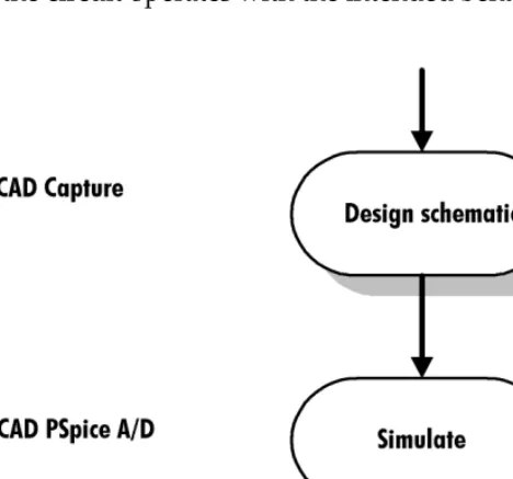
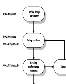
[image:20.612.201.476.236.576.2]The PSpice Optimizer is fully integrated with other Orcad programs. This means you can design your circuit with Orcad Capture, simulate with Orcad PSpice A/D (or Orcad PSpice), analyze results with the PSpice A/D waveform viewer and optimize performance within the same environment. Figure 1 illustrates the typical design flow for circuit optimization.
Figure 1 Optimization design flow. Because you can use Capture and
PSpice A/D to design and simulate at the system, subcircuit, or component level, use the PSpice Optimizer to optimize at whatever level is most appropriate.
Terms you need to understand
Optimization
Optimization is the process of fine-tuning a design by varying design parameters between successive simulations until performance comes close to (or exactly meets) the ideal performance.The PSpice Optimizer solves four types of optimization problems as described in Table 1.
Table 1 Optimization problems*.
* All four cases allow simple bound constraints; that is, lower and upper bounds on all of the parameters. The PSpice Optimizer also handles nonlinear goals and constraints.
Problem type PSpice Optimizer action Example
Unconstrained minimization Reduces the value of a single goal Minimize the propagation delay through a logic cell
Constrained minimization Reduces the value of a single goal while satisfying one or more constraints
Minimize the propagation delay through a logic cell while keeping the power consumption of the cell less than a specified value
Unconstrained least squares**
** Use unconstrained least squares when fitting model parameters to a set of measurements, or when minimizing more than one goal.
Reduces the sum of the squares of the individual errors (difference between the ideal and the measured value) for a set of goals
Given a terminator design, minimize the sum of squares of the errors in output voltage and equivalent resistance
Constrained least squares Reduces the sum of squares of the individual errors for a set of goals while satisfying one or more constraints
Parameter
A parameter defines a property of the design for which the PSpice Optimizer attempts to determine the best value within specified limits. A parameter can:• Represent component values (such as resistance, R, for a resistor).
• Represent other component property values (such as slider settings in a potentiometer).
• Participate in expressions used to define
component values or other component property values.
The PSpice Optimizer can optimize designs with up to eight variable parameters.
For example: A potentiometer part in a schematic uses the SET property to represent the slider position. You can assign a parameterized expression to this property to represent variable slider positions between 1 and 0. During optimization, the PSpice Optimizer varies the parameterized value of the SET property.
Specification
A specificationdescribes the ideal behavior of a design in terms of goals and constraints. For example: For a given design, the gain shall be 20 dB ±1 dB; for a given design, the 3 dB bandwidth shall be 1 kHz; for a given design, the rise time must be less than 1 usec. A design can have up to eight goals and constraints in any combination, but there must always be at least one goal. You can easily change a goal to a constraint andvice-versa.
The PSpice Optimizer accepts specifications in two formats: internal and external.
Internal specifications
An internal specification is composed of goals and constraints defined in terms of target values and ranges, which are entered into the PSpice Optimizer through dialog boxes.
See Chapter 6, Tutorial: Exploring design tradeoffs (active filter) for a working example showing parameterized slider values.
For more information, see Goal and
External specifications
An external specification is composed of measurement data, which are defined in an external data file that is read by the PSpice Optimizer.
Target value
A target value is the ideal operating value for a characteristic of the design as defined by a goal or constraint specification.Goal
A goal defines the performance level that the design should attempt to meet (for instance, minimum power consumption). A goal specification includes:• The name of the goal.
• A target value and an acceptable range.
• A circuit file to simulate.
• An evaluation for measuring performance.
• An analysis type used for simulation-based evaluations.
The goal specification can also include:
• The name of the file containing the PSpice A/D goal function definitions (.PRB file).
• When using an external specification, the name of the file containing measured data and the columns of data to be used as reference.
Constraint
A constraint defines the performance level that the design must fulfill in which the target value exceeds, falls below, or equals a specified value (for instance, an output voltage that must be greater than a specific level). The constraint specification includes:• The name of the constraint.
• A target value and an acceptable range.
• A circuit file to simulate. (See note on previous page.)
• An evaluation for measuring performance.
• An analysis type used for simulation-based evaluations.
• An allowed relationship between measured values and the target value, which can be one of the following:
The constraint specification can also include the name of the file containing the PSpice A/D goal function
definitions (.PRB file).
Constraints are often nonlinear functions of the parameters in the design.
For example: Bandwidth can vary as the square root of a bias current and as the reciprocal of a transistor
dimension.
Performance
The performance of a design is a measure of how closely its specifications’ calculated valuesapproach their target values for a given set of parameter values. When there are multiple specifications (at least one of which is a goal), the PSpice Optimizer uses the sum of the squares of their deviations from target to measure closeness. For a single specification (goal), the PSpice
<= measured value must be less than or equal to the target value
= measured value must equal the target value
>= measured value must be greater than or equal to the target value
Optimizer uses either the goal’s value, or the square of its deviation from target.
Each aspect of a design’s performance is found by either:
• First performing the appropriate simulation, then running PSpice A/D to measure characteristics of the resulting waveform(s)
or
• Evaluating PSpice Optimizer expressions In many cases (particularly if there are multiple conflicting specifications), it is possible that the PSpice Optimizer will not meet all of the goals and constraints. In these cases, optimum performance is the best compromise
solution—that is, the solution that comes closest to satisfying each of the goals and constraints, even though it may not completely satisfy any single one.
Evaluation
An evaluation is an algorithm thatcomputes a single numerical value, which is used as the
measure of performance with respect to a design specification.
The PSpice Optimizer accepts evaluations in one of these three forms:
• Single-point PSpice A/D trace function • PSpice A/D goal function
• PSpice Optimizer expression
Given evaluation results, the PSpice Optimizer determines whether or not the changes in parameter values are improving performance, and determines how to select the parameters for the next iteration.
Trace function
A trace function defines how to evaluate a design characteristic when running asingle-point analysis (such as a DC sweep with a fixed voltage input of 5 V). For example: V(out) to measure the output voltage; I(d1) to measure the current through a component.
PSpice A/D goal function
A goal function defines how to evaluate a design characteristic when running any kind of analysis other than a single-point sweep analysis. A goal function computes a single number from awaveform. This can be done by finding a characteristic point (e.g., time of a zero-crossing) or by some other operation (e.g., RMS value of the waveform).
For example, you can use PSpice A/D goal functions to:
• Find maxima and minima in a trace.
• Find distance between two characteristic points (such as peaks).
• Measure slope of a line segment.
• Derive aspects of the circuit’s performance which are mathematically described (such as 3 dB bandwidth, power consumption, and gain and phase margin).
To write effective goal functions, determine what you are attempting to measure, then define what is
mathematically special about that point (or set of points).
Note
Be sure that the goal functions accurately measure what they are
intended to measure. Optimization results highly depend on how
well the goal functions behave. Discontinuities in goal functions
(i.e., sudden jumps for small parameter changes) can cause the
optimization process to fail.
PSpice Optimizer expression
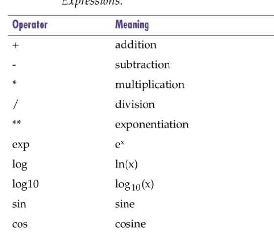
A PSpice Optimizer expression defines a design characteristic. The expression is composed of optimizer parameter values, constants, and the operators and functions shown in Table 2. For example: To measure the sum of resistor values for two resistors with parameterized values named R1val and R2val, respectively, use the PSpice Optimizer expressionR1val + R2val.
Refer to the Goal Function Wizard in
PSpice A/D and your PSpice A/D
User’s Guide for information on how to develop and specify goal functions. Here are some quick tips. In PSpice A/D: • To test the value returned by a
specified goal function, choose Eval Goal Function from the Trace menu.
• To see the waveforms and marked
points used to evaluate a goal function, select Display Evaluation in the Options dialog box (from the Tools menu, choose Options to display this dialog box).
Note
Unlike trace functions and goal functions, PSpice Optimizer
expressions are evaluated without using a simulation.
Derivative
A derivative defines mathematically how a specification value changes with a small change in parameter value. [image:27.612.64.344.90.328.2]For a given design, the PSpice Optimizer calculates derivatives for each specification with respect to each parameter. Within an applicable range, the optimizer uses the derivatives to estimate new values for the goals and constraints.
Table 2 Valid Operators and Functions for PSpice Optimizer Expressions.
Operator Meaning
+ addition
- subtraction
* multiplication
/ division
** exponentiation
exp ex
log ln(x)
log10 log10(x)
sin sine
cos cosine
tan tangent
atan arctangent
Primer: How to optimize a
design
2
Chapter overview
This chapter guides you through the basic steps needed to setup and run an optimization using a simple diode biasing design.
• Optimizing a diode biasing circuit—the objective on page 2-31 describes the sample circuit and its ideal operating characteristics.
• Why use optimization? on page 2-32 explains why fine-tuning your design using the PSpice Optimizer saves time.
• Phase One: Developing the design on page 2-33 walks you through the steps needed to create a working design.
• Phase Two: Setting up the optimization on page 2-35 walks you through the steps needed to define the
Optimizing a diode biasing
circuit—the objective
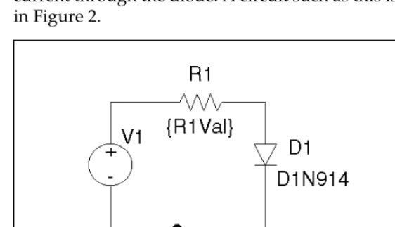
[image:31.612.62.343.191.353.2]Assume that you want to design a circuit that drives a current of 1mA (±5 µA) through a diode (D1N914) using a 5Vvoltage source and a series resistor to control the current through the diode. A circuit such as this is shown in Figure 2.
Figure 2 Diode biasing design example.
Why use optimization?
To solve the problem manually, you could assign an arbitrary value to R1, manually calculate the current, then make an educated guess to adjust the values until a
satisfactory solution is found. Or, you might use a simulation to sweep the value for R1 with a DC Sweep analysis, carefully analyzing the results to find the best solution.
These manual methods have two major disadvantages:
• Because the diode is a non-linear device, manual calculations can be time-consuming.
• Sweeping a parameterized value can take a large number of simulations, depending on the range and increment selected.
The PSpice Optimizer automates these processes by handling calculations for you and intelligently directing the series of simulations. Given results of the previous simulations, the optimizer automatically adjusts the parameterized value of R1 for the next run, thus eliminating unnecessary iterations, which in turn, provides a solution more quickly and with less effort. Once the PSpice Optimizer settles on the best solution, you can still explore available tradeoffs. When done manually, this iterative process can be difficult and frustrating. With the optimizer, you can tweak the parameter(s) and immediately determine whether the design still meets specifications. You can also change the value of the specification(s) and immediately determine how parameter values change. If you are dissatisfied with the result after any change, you can always return to the last set of values.
When solving complex problems, the manual approach can be too unwieldy to consider. For example:
• When your design has multiple parameters or complicated parameter interactions, you may find it’s nearly impossible to know which parameters to change, and how best to change them.
Phase One: Developing the
design
Before optimizing, you must have a working circuit. This means first drawing the design, then iteratively
[image:33.612.100.334.192.410.2]simulating with PSpice A/D and adjusting the design until the circuit operates with the intended behavior.
Figure 3 Design flow for developing the design.
To draw the schematic page for the diode biasing design
1 In Capture’s Project Manager, choose New under the File menu, then choose Project.
2 Enter MYDIODE as the name of the new project. 3 Select Analog or Mixed-signal Circuit Wizard to make
this a design that can be simulated with PSpice. 4 Click OK, then click Finish.
A blank schematic page will appear.
5 From the Place menu, choose Part to select and place the following parts on the schematic page:
Phase 1 is also the time to investigate: • The effects of individual components
by replacing component values with parameters or parameterized expressions.
R resistor R1
D1N914 diode D1
VSRC voltage source V1
6 Choose Place Ground to select and place the following simulaton parts on the schematic page:
0 analog ground 0
7 From the Place menu, choose Wire to connect the parts as shown in Figure 2.
8 Click on the VSRC part (V1) to select it.
9 From the Edit menu, choose Properties, then User Properties to set V1’s DC property to 5V.
10 From the File menu, choose Save.
The PSpice optimizer advantage
To determine a value for R1 manually, you can set up a parametric analysis of a DC sweep where:
• The value of R1 steps from 4 k to 5 k in increments of 0.1 k
• The DC sweep analysis is a single-point voltage analysis at 5 V
Such an analysis requires eleven PSpice simulations. Using Probe, the resistor value giving rise to 1 mA current through D1 is 4.14 k.
The remainder of this chapter shows how to use the PSpice Optimizer to determine the same solution automatically using fewer simulations.
Phase Two: Setting up the
optimization
[image:35.612.70.339.180.518.2]Now that preliminary design development is complete, you are ready to define the optimization parameters, goals, and constraints.
Defining design parameters
To define parameters for optimization, you must:
• Identify the parameters to adjust for optimization and assign a unique name to each one.
• Set up each parameter as a global optimization parameter using Capture.
• Select which components in the design are affected by the parameter and, for each component, replace its value (e.g., the value of its VALUE property) with an expression that includes the parameter name.
To prepare the diode design example for optimization, you need to parameterize the value of R1 and specify its optimization properties.
To set up the value of R1 as a parameter named R1Val
1 From Capture’s PSpice menu, choose Place Optimizer Parameters to place an instance of the OPTPARAM part.
2 Double-click on the OPTPARAM part, then click the User Properties button.
3 Set R1val properties as shown in the Optimizer Parameters dialog box.
4 Click OK.
You can also define optimization parameters in the PSpice Optimizer by selecting Parameters from the Edit Menu. See Adding and editing
parameters on page 3-60 for more information.
The parameter settings are: Name= R1Val
Initial Value= 5k Current Value= 5k Lower Limit= 100 Upper Limit= 10k Tolerance = 10%
5 Double-click the 1 k label for R1 and enter {R1val} to parameterize the value of R1.
6 Click OK.
Setting up goals and constraints
Before you can evaluate and improve the circuit’s performance, answer these questions:
• What operating characteristics do I want to measure? • How do the parameters affect the operating
characteristics?
After you’ve answered these questions, you are ready to:
• Set up the analyses needed to evaluate the performance measures.
• Develop the performance measure algorithms.
• Fully define the goals and constraints in terms of these performance measures and analyses.
Setting up analyses for each goal and constraint
For each specification, you must define an analysis type: AC, DC, or transient. This is the analysis that PSpice will run in order to generate results that will be used by the PSpice Optimizer to measure performance.
For the diode design example, you want to monitor the value of I(D1) at a fixed input voltage of 5 V while the optimization parameter, R1val, is varied. This means setting up a single-point voltage sweep.
To set up a single-point voltage sweep analysis at 5 volts
1 From Capture’s PSpice menu, choose New Simulation Profile, then enter a name (DC Sweep) for the profile.
3 To fix the voltage of V1, fill in the DC Sweep dialog box as shown.
4 Click OK to save the profile.
Developing performance measures
To measure performance you must define an evaluation algorithm for each specification. There are three
alternatives:
• Trace function (for single-point simulations)
• Goal function
• PSpice Optimizer expression
When the evaluation is anything other than a single-point simulation or PSpice Optimizer expression, you must develop goal functions to derive values from the simulation results. Developing goal functions is an iterative process that involves writing the goal function, simulating the design, and testing the goal functions against actual results to make sure you are measuring the waveform characteristics you intended.
A goal function is not required for the diode design example. You are examining the trace of R1Val versus
The DC Sweep settings are: Swept Var Type = Voltage Source Sweep Type= Value List Name = V1
Values= 5v
See Evaluation on page 1-25 and the sections that follow for definitions of trace function, goal function, and PSpice Optimizer expression.
Orcad supplies standard goal functions for AC, DC, and transient analyses in the file PSPICE.PRB. (This file resides in the Orcad root/PSpice directory.) You can add goal functions to this file, or create a local .PRB file for use with a specific design. See Chapter 7, Tutorial: Using constrained optimization (MOS amplifier) for examples of Probe goal functions used to evaluate performance.
Refer to your PSpice A/D User’s
I(D1) which shows the relationship between the value of R1 and the diode forward current. Because only a single point on the curve is of interest, the trace function, I(D1), is the appropriate evaluation.
Defining specifications: goals and constraints
Now that you’ve completed the preliminary groundwork, you are ready to define the properties for goals and constraints. So far, you have performed all steps in Capture. To finalize setup, you must specify the goal for the diode design example using the PSpice Optimizer.
To define the design goal, Id1, for the diode design example
1 From Capture’s PSpice menu, choose Run Optimizerto start the PSpice Optimizer.
The PSpice Optimizer window appears showing the parameter R1val that you defined using the
OPTPARAM part in the your design.
2 From PSpice Optimizer’s Edit menu, choose Specifications.
3 In the Specifications dialog box, click Add. 4 Enter Id1 properties, as shown below.
The goal specification settings are:
Name = Id1
Target = 1ma
Range = 5ua
Analysis = DC Circuit File = mydiode Evaluate = I(d1)
Phase Three: Running an
optimization
[image:40.612.206.471.179.579.2]Now that you have defined the parameters, specifications, and evaluations for the design, you are ready to optimize, adjust, and finalize your design.
Running the PSpice Optimizer
You can use the PSpice Optimizer to:
• Optimize the circuit to completion (from the Tune menu, select Auto).
• Evaluate performance for a single set of parameter values (from the Tune menu, select Update
Performance).
• Compute derivatives of each specification with respect to each parameter (from the Tune menu, select Update Derivatives).
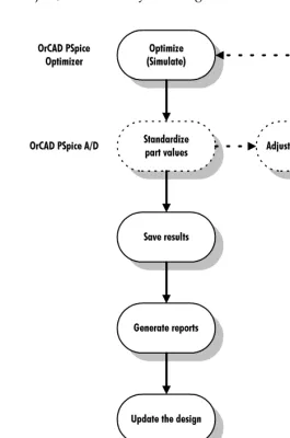
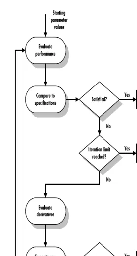
When you select Auto from the Tune menu, the PSpice Optimizer automatically computes the derivatives for each specification with respect to each parameter (Figure 6). Using the derivatives, the optimizer
determines the direction in which to vary the parameters, and changes parameter values accordingly until it achieves a reduction in the overall error. After updating the parameters, the optimizer computes new derivatives and repeats the process until one of the following occurs:
• Specifications are met (success).
• No more progress can be made (failure).
• You manually interrupt the process.
To start optimizing the diode design
1 From the Tune menu, select Auto and click Start.
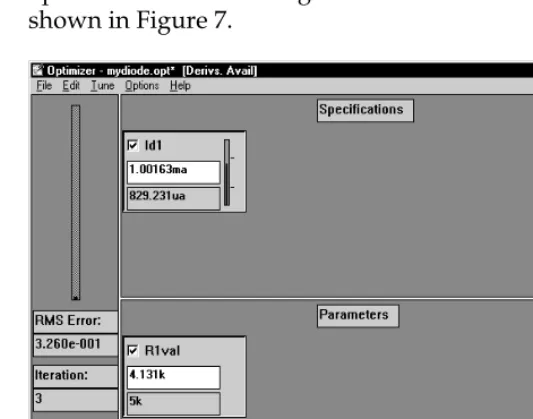
[image:43.612.78.345.228.438.2]The PSpice Optimizer performs several simulations. For each iteration of the parameter values, the optimizer calculates overall performance and graphically displays the results. The optimizer also calculates the value of the trace function, I(d1), and displays the new value in the specifications area of the PSpice Optimizer window. After three iterations, the optimizer should converge on a solution of 4.131 k, as shown in Figure 7.
Figure 7 Optimization results for the diode design example.
Adding a constraint and rerunning the PSpice
Optimizer
So far, you have optimized for a single goal, Id1. Now suppose you want to add a condition, or constraint, on the power dissipated in resistor R1.
In the diode example, the derivative at R1=5 k is –1.62 x 10 -7, or
This indicates that a 1 ohm increase in R1 will produce a decrease of 0.162 uA in Id1. To verify this, try reducing the value of R1 by 100 ohms (to 4.9 kohm) and simulate. This increases the diode current by 16.2 uA and agrees with the derivative information.
R1
∂∂ ( )Id 1.62 7 – ×10 –
=
Constraints are defined like goals (using the Edit Specification dialog box) with two additions. In the Internal frame, you must:
• Select the Constraint check box.
• Choose the constraint type (>= target, = target, or <= target).
The constraint type specifies the required relation between what is evaluated (as defined in the Evaluate text box) and the target value (defined in the Target text box).
To define the constraint for power dissipation in R1
The power dissipated in R1 must be less than or equal to 4mW±400 uW. Define the constraint by doing the
following:
1 From PSpice Optimizer’s Edit menu, choose Specifications.
2 In the Specifications dialog box, click Add.
3 Enter the power (Pc) constraint properties, as shown below.
The Evaluate text box contains the expression for measuring dissipated power. For each iteration, PSpice A/D will compute dissipated power by taking
The constraint specification settings are:
Name = Pc
Target = 4mW
Range = 400uW
Constraint selected
Type = <=target
the product of the voltage across the resistance and the current through it.
4 To calculate the performance of the design for initial parameter and specification values only (one
iteration):
a From the Edit menu, choose Reset Values. b From the Tune menu, choose Update
Performance.
Note the appearance of the progress indicator in the Pc box. Since Pc is a less than or equal to
constraint, the progress indicator has a tick mark 1/4 of the way up. The vertical bar within the indicator is below the tick mark; this means that the constraint is currently satisfied.
5 From the Tune menu, choose Auto and click Start to start optimization.
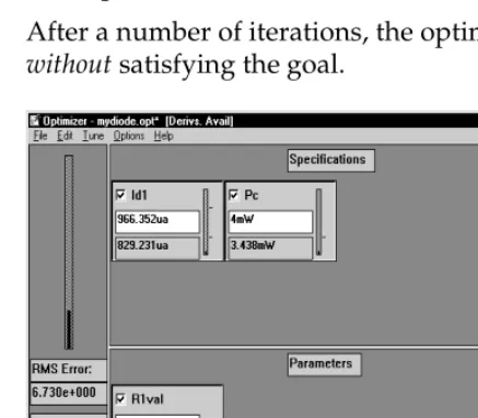
After a number of iterations, the optimization ends
[image:45.612.80.299.338.529.2]without satisfying the goal.
Figure 8 Results after adding the power constraint.
Note that the power dissipated in R1 is exactly equal to the target value of the constraint (4 mW). In this example there is no feasible solution to the problem.
progress indicator
However, the PSpice Optimizer found the lowest value for Id1 which does not violate the constraint.
Changing the constraint and rerunning the PSpice
Optimizer
You can examine the effect the Pc constraint has on performance by changing its constraint type so the power dissipation in the resistor must be greater than or equal to 4mW.
To change the Pc constraint type to “greater than or equal”
1 In PSpice Optimizer, double-click the lowerright-hand corner of the Pc box.
2 In the Edit Specifications dialog box, change Type to >= target.
3 Click OK.
To run the optimization with the modified constraint
1 Test performance with the updated constraint:a From the Edit menu, choose Reset Values. b From the Tune menu, choose Update
Performance.
The Pc constraint is initially violated because the power dissipation is less than 4 mW.
2 From the Tune menu, choose Auto and click Start to start optimization.
The PSpice Optimizer finds a solution which satisfies both the goal (current of 1 mA) and the constraint (power dissipated in the resistor greater than 4 mW). Figure 9 shows the results.
Figure 9 Results after changing the constraint type.
Using standard component values
When an optimization completes successfully, the optimizer displays the new parameter values in the PSpice Optimizer window. However, each calculated value might not correspond to an actual value that is available with off-the-shelf components. For example, resistors are not readily available in all possible values.
You can use the PSpice Optimizer to select standard component values. The optimizer either:
• rounds to the nearest value, or
• computes values based on the most recent optimization run.
To round to the nearest standard component value
1 From the Edit menu, select Round Nearest.
R1val’s current value changes to 3.9 k in accordance with the specified 10% tolerance.
See Using standard part values on page 3-79 for more information, including how the PSpice Optimizer uses tolerances and limits when standardizing values.
Producing reports
You can use the PSpice Optimizer to generate a report summarizing:
• current settings for parameter, specification, and program options.
• calculated derivatives and Lagrange multipliers.
To generate a summary report
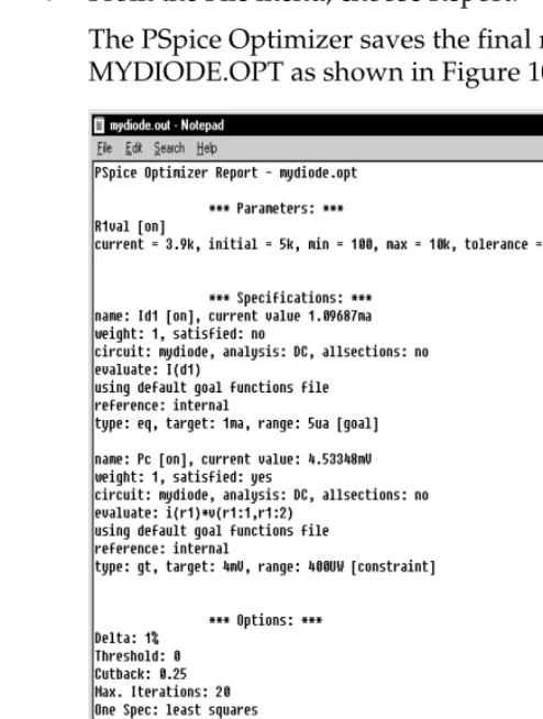
1 From the File menu, choose Report.
[image:48.612.205.452.236.563.2]The PSpice Optimizer saves the final results to MYDIODE.OPT as shown in Figure 10.
Saving results
When you have finished optimizing, you can save all of the optimizer data, including the current values for all parameters and specifications.
To save the optimizer data for the diode design
1 From the File menu, choose Save.
The PSpice Optimizer updates the MYDIODE.OPT file. All of the options settings are also saved.
Updating the schematic
Having completed the optimization, you can update the data in the schematic file to include the optimized parameter values.
To update the diode schematic with the current parameter values
1 From the Edit menu, select Update Schematic.
Recall that R1Val was initially set at 5.0 k in the schematic file. When you select Update Schematic, the PSpice Optimizer sends a message to Capture to update the design file. Capture writes the new parameter value of 3.9 k to the OPTPARAM part on the schematic (as the current value).
[image:49.612.62.339.338.594.2]Figure 11 shows the updated schematic for the diode design.
Using the PSpice Optimizer
3
Chapter overview
This chapter describes in general terms how to complete any task using the PSpice Optimizer, including:
• How to activate the PSpice Optimizer and load a design, page3-52.
• How to interact with the PSpice Optimizer window,
page3-55.
• How to add and edit optimization parameters,
page3-60.
• How to add and edit goals and constraints, page3-63. • How to measure and optimize performance, page3-68. • How to explore design tradeoffs, page3-71.
• How to generate result summaries including
Lagrange multipliers and derivative values, page3-76. • How to finalize the design: standardize component
Starting and loading the PSpice
Optimizer
This section describes how to:
• Start the PSpice Optimizer.
• Set special startup options.
• Load a design.
Starting the PSpice Optimizer
Start the PSpice Optimizer program either from:
• Capture
or
• The Windows Start menu
From Capture
To start the PSpice Optimizer from within Capture
1 From Capture’s PSpice menu, choose Run Optimizer.
If you have an active schematic loaded in the schematic editor when you choose Run Optimizer, any optimization parameters defined with the
OPTPARAM part and any existing setup information contained in the corresponding optimization file (.OPT) are automatically loaded into the PSpice Optimizer.
From the Windows Start menu
From the Start menu, there is a program folder which contains Windows shortcuts for all installed Orcad programs, including the PSpice Optimizer.
To start the PSpice Optimizer from the Windows Start menu
From the Windows Start menu, select the Orcad program folder and then the PSpice Optimizer shortcut to start optimizer.
The optimizer starts without an optimization setup. See Loading a different optimization file on page 3-54 for further instructions.
Changing startup options
The PSpice Optimizer supports two command line options, which are used to:
• Start the optimizer with an initialization file other than the default (PSPICE.INI).
• Automatically load an optimization file (.OPT) after startup.
You can add one or both options to the command line.
To change the initialization file used by the PSpice Optimizer
In the Optimizer command line, use the -i option as follows:
OPTIMIZE -i initialization_file_name
Because you can start the PSpice Optimizer from either Capture or from the Windows Start menu, we recommend that you change the command line definition as follows:
To automatically load an optimization file after startup
In the PSpice Optimizer command line, add the name of the optimization file as follows:
OPTIMIZE optimization_file_name
The following command line example shows how to start the optimizer at all times with an initialization file named MYINIT.INI and an optimization file named MYDESIGN.OPT:
OPTIMIZE mydesign.opt -i myinit.ini
Loading a different optimization file
Once you have started the PSpice Optimizer, you can change to a new or different optimization file at any time.
To start a new optimization
1 From the File menu, choose New.
To load an existing optimization setup
1 From the File menu, choose Open.The PSpice Optimizer Window
The PSpice Optimizer window contains three areas:
• Specifications area
• Parameters area
[image:55.612.65.300.204.432.2]• Error gauge area
Figure 12 illustrates their position in the window.
Figure 12 The PSpice Optimizer window.
error gauge area specifications area
Specifications area
The specifications area can show up to eight specification boxes where each box represents either a goal or a constraint. Figure 13 illustrates the fields contained in each box.
Figure 13 Example of a specification box.
The contents of the box varies depending on the source for the specifications—either internal or external. The
following sections describe the differences in the initial and current value fields, and the progress indicator.
Internal specifications
Initial value
The initial value field displays a single performance measure that the PSpice Optimizer sets when you start an optimization. The optimizer derives this value from the initial optimization parameter values you defined in the schematic (or the optimizer).Current value
The current value field displays the performance measure that corresponds to the current parameter values. Current values are updated each time an optimization iteration makes progress. When the current value satisfies the specification (that is, the current value is within the allowed range of the target) then the progress indicator turns from red to green, and the PSpice Optimizer considers the specification satisfied.initial value current value
enable/disable check box
progress indicator
edit specification hot spot
For more information on the enable/disable check box, see
Excluding parameters and specifications from optimization on page 3-75. For more information on the edit hot spot, see Selecting a specification to edit on page 3-68.
If derivative data is available, you can change the value in this field to explore how parameter values might change. See
Progress indicator
As mentioned above, the progress indicator shows red while the specification is violated, and changes to green when the specification is satisfied.You can monitor progress as the optimization runs by watching the progress indicator and observing the height of the vertical black bar relative to the tick mark(s) to the right. The number and relative position of the tick mark(s) varies depending on the type of specification:
• Two tick marks for a goal or equality constraint denote the acceptable range around the target value.
• A single tick mark one-quarter of the way up denotes a less than or equal to constraint.
• A single mark three-quarters of the way up denotes a
greater than or equal to constraint.
External specifications
Initial value
The initial value field is used in a different way from an internal specification: the field contains a pair of numbers separated by a ‘/’ character. The first number is the number of subgoals in the external specification that are satisfied. The second number is the total number of subgoals in the external specification.Current value
The current value field is used in a different way from an internal specification: the field contains a pair of numbers as described above for initial value.Progress indicator
The progress indicator shows the fraction of subgoals that are satisfied. The indicator turns from red to green when all of the subgoals are satisfied.For example: If an external specification has 20 subgoals and five are satisfied, the current value field reads 5/20 and the bar in the progress indicator rises to the
one-quarter mark.
goal or equality constraint
less than or equal to constraint
Parameters area
The parameters area can show up to eight parameter boxes. Figure 13 illustrates the fields contained in each box.
Figure 14 Example of a parameter box.
The following sections explain the initial and current value fields in the parameter box.
Initial value
The initial value field displays a single value taken from the parameter specification that you set up either in Capture (using the OPTPARAM part) or in the PSpice Optimizer (from the Edit menu, choose Parameters).Current value
Initially, the current value is taken from the parameter specification you set up in either the schematic or the PSpice Optimizer. With each iteration of an optimization, the optimizer updates the current value field with the new set of parameter values.initial value current value
enable/disable check box
edit parameter hot spot
For more information on the enable/disable check box, see
Excluding parameters and specifications from optimization on page 3-75. For more information on the edit hot spot, see Selecting a parameter to edit on page 3-62.
If derivative data is available, you can change the value in this field to explore how specification values might change. See
Error gauge area
The error gauge area has an error indicator and shows information reflecting the overall condition of the optimization.
The error gauge shows how far the goals are from their target values. Initially, the indicator displays 100%. As the optimization proceeds, the error falls as the goals
approach their target values. The PSpice Optimizer displays the RMS of the normalized value of the goals in the RMS Error field.
If all of the specifications meet the target values exactly, the error is zero. If the optimization succeeds by finding a solution that works within the set ranges, but does not meet the target values exactly, the error represents the combined error of all of the specifications.
Note
The RMS error reflects only those goals that are enabled. The error
does not include contributions from constraints, nor does it reflect
any specifications that are disabled.
Adding and editing parameters
This section describes how to create and change
optimization parameters using the PSpice Optimizer. This means you can also edit the properties of parameters that you defined in a schematic.
Note
You are limited to eight parameters per optimization file. This limit
includes parameters that you have defined but disabled for a given
run.
Adding a parameter
There are two ways to add a parameter using the PSpice Optimizer:
• Create the parameter from scratch.
• Copy an existing parameter and change its name.
To create a parameter from scratch
1 From PSpice Optimizer’s Edit menu, choose Parameters.
Any optimization parameters that you have already established in the schematic appear in the selection list.
2 In the Parameters dialog box, either:
• click Add
or
• double-click the blank line following the parameter list
You can also define parameters in Capture using the OPTPARAM part. See Defining design parameters on page 2-36
3 In the Edit Parameter dialog box, set the controls as described in Table 3.
To create a parameter based on an existing parameter
1 From PSpice Optimizer’s Edit menu, chooseParameters.
2 Select the parameter that you want to copy and click Copy.
Notice that the Insert button is now enabled (no longer grayed out)
3 Click Insert to add a copy of the selected parameter to the parameter list.
The optimizer inserts the new parameter immediately above the highlighted parameter.
[image:61.612.360.503.65.191.2]4 Select the new parameter in the list and click Change. Table 3 Edit parameter dialog box controls.
Control Name Meaning
Name Parameter name; for a new parameter, double-click <<new>> and enter a text string that is unique to the current optimization file.
Current Value Latest parameter value; for a new parameter, set Current Value equal to Initial Value.
Initial Value Starting value for the parameter.
Upper Limit Highest allowable value for the parameter.
Lower Limit Lowest allowable value for the parameter.
Tolerance Tolerance level (1%, 5%, etc.) to use when standardizing component values.
5 Change the Name text box to a unique name, and change any other controls as needed.
6 When finished, click OK to return to the Parameters dialog box.
Note
You cannot copy a parameter description from one optimization file
to another. Instead, save an entire optimization file under a new
name, then edit the new version as needed.
Selecting a parameter to edit
You can change the properties of an existing parameter at any time using the Edit Parameter dialog box.
To display the Edit Parameter dialog box for a parameter
1 Do one of the following:• In the parameters area of the PSpice Optimizer window, double-click the lower right-hand corner of the box for the parameter you want to edit. or
• From the Edit menu, choose Parameters, then select the parameter you want to edit, and click Change.
double-click here
Adding and editing specifications
This section describes how to create and change
specifications—that is, goals and constraints—using the PSpice Optimizer.
Note
You are limited to eight specifications per optimization file. This
limit includes specifications that you have defined but disabled for
a given run.
Adding a specification
There are two ways to add a specification using the PSpice Optimizer:
• Create the specification from scratch.
• Copy an existing specification and change its name.
To create a specification from scratch
1 From PSpice Optimizer’s Edit menu, choose Specifications.
2 In the Specifications dialog box, either:
• click Add
or
3 In the Edit Specification dialog box, set the controls as described in Table 4.
Table 4 Edit specification dialog box controls.
Control name Meaning
Name Specification name; for a new specification, double-click <<new>> and enter a text string that is unique to the current optimization file.
Reference • Select Internal when defining the specification’s target value and range in this dialog box.
• Select External when defining the specification’s measurement data using a file (e.g., for curve fitting).
Weight Relative weight of the specification. To give a specification more weight, assign a number that is higher than that for the other specifications.
Enabled When enabled, includes the
specification in the next run. If cleared, excludes the specification.
Internal specification
Target Ideal value for the specification.
Range Delta applied to Target, defining the acceptable range of values; i.e., Target ± Range.
For example: If Target=10 and Range=2, then the PSpice Optimizer accepts values from 9 to 11.
Constraint When enabled, defines the specification as a constraint (not a goal).
External Specification
File Name of the file that contains the measured data.
X Column Name Heading for the data column in File containing the independent (X) values.
Y Column Name Heading for the data column in File containing the dependent (Y) values
Tolerance Tolerance value used when standardizing component values. Syntax: < 0 ≤ integer value≤ 100 >%
Analysis Settings
(Analysis Type) Kind of analysis used for simulation-based evaluations.
• Select AC for AC sweep analysis.
• Select DC for a DC sweep analysis.
• Select Tran for a transient analysis.
Circuit File Set to either:
• the name of the circuit file PSpice uses for simulation, or
• leave blank if the Evaluate text box contains a PSpice Optimizer expression.
Evaluate* Trace function, Probe goal function, or PSpice Optimizer expression used to measure performance.
* See Defining an evaluation for an external specification on page 3-67 for the purpose and use of the ‘!’ part in the Evaluate edit control. Table 4 Edit specification dialog box controls. (continued)
[image:65.612.367.489.111.208.2]Control name Meaning
Figure 15 Sample format for an external specification.
Vbe Ic
4.0E-01 6.05E-06
4.1E-01 8.90E-06
4.2E-02 1.31E-05
X column name
To create a specification based on an existing specification
1 From PSpice Optimizer’s Edit menu, chooseSpecifications.
2 Select the specification that you want to copy and click Copy.
Notice that the Insert button is now enabled (no longer grayed out)
3 Click Insert to add a copy of the selected specification to the parameter list.
The optimizer inserts the new specifications immediately above the highlighted specification. 4 Select the new specification in the list and click
Change.
5 Change the Name text box to a unique name, and change any other controls as needed.
6 When finished, click OK to return to the Specifications dialog box.
Defining an evaluation for an external specification
When defining evaluations for external specifications, use the ‘!’ part within the evaluation as a placeholder for data in the external file. For each of the subgoals in the external file, the PSpice Optimizer first replaces the ‘!’ character with the X column data value (defined in the X Column Name text box in the Edit Specification dialog box), and then proceeds with evaluation. This approach allows a waveform analysis goal function or PSpice Optimizer expression to track the independent data value.
To set up an evaluation for an external specification
1 Create the goal function or PSpice Optimizer expression.
2 In the Edit Specification dialog box, enter the evaluation in the Evaluate text box as follows:
Substitute the ‘!’ character for every X value argument; i.e., wherever a measured subgoal value should appear.
For example: Suppose that you want to fit a set of data measured at different values of Vtest (2.0, 2.5, and 3.0 volts), using the goal function:
YatX(V(out), x_value)
to measure the output of the design. To use this with an external specification, replace x_value with the ‘!’ character and enter the evaluation:
YatX(V(out), !)
into the Evaluate text box for the specification.
As the fitting process proceeds, the PSpice Optimizer passes the following goal functions (one for each measured data point) to PSpice A/D:
YatX(V(out), 2.0)
YatX(V(out), 2.5)
YatX(V(out), 3.0)
After substitution, the PSpice Optimizer does one of the following depending on the kind of evaluation:
• For a waveform analysis goal function, the optimizer sends the substituted goal function to PSpice A/D for evaluation.
• For a PSpice Optimizer expression, the optimizer evaluates the expression directly.
Selecting a specification to edit
You can change the properties of an existing specification at any time using the Edit Specification dialog box.
To display the Edit Specification dialog box for a goal or constraint
1 Do one of the following:• In the specifications area of the PSpice Optimizer window, double-click the lower right-hand corner of the box for the specification you want to edit.
• From the Edit menu, choose Specifications, then select the specification you want to edit, and click Change.
Measuring and Optimizing
Performance
This section describes how to:
• Optimize your design once all of the parameters and specifications are defined.
• Monitor progress using the waveform viewer in PSpice A/D.
Optimizing Your Design
Optimization is a two-stage process:
1 Running one evaluation to ensure that the circuit is valid and that it simulates.
2 Starting the optimization process.
double-click here
To optimize your design
1 From the Tune menu, choose Update