Freescale Semiconductor
SLK0100AN
Application
Note
Rev. 0, 1/2007
Using the Project Board LCD Display at 3.3 volts
By: John McLellan
Applications Engineering
Austin, TX
1 Introduction
This document guides you through the steps
necessary to use the LCD attached to the
Freescale Project Board when power select is
configured for 3.3V operation.
The hardware setup section will define the
problem, address risks associated with
implementing the solution, and walk you
through the modification required to the project
board.
Refer to the project board schematic available at
www.freescale.com\universityprograms
for
additional resources.
Contents
1 Introduction... 1
2 Naming Conventions ... 2
3 Modifying the Project Board ... 2
3.1 Problem Statement ... 2
3.2 Risks associated with this solution
implementation ... 3
3.3 Solution ... 3
4 Revision History ... 5
Applicable part numbers:
2 Naming Conventions
For the purposes of this document the following terminology will refer to these interchangeable
parts numbers.
MCU Project Board
PBMCSULK, MCUSLK (identified by on-board labels such as MCU
PROJECT BOARD – 2 and MCU PROJECT BOARD)
3 Modifying the Project Board
3.1 Problem Statement
In the default configuration the Project Board is connected to Vdd. When using a microcontroller that
operates at 3.3V, the user changes the VDD_SEL header on the project board (5V or 3.3V) which
sources Vdd. Therefore, when the project board is in the 3.3V configuration the LCD Display does not
reach its operational voltage.
[image:2.612.78.275.296.422.2]Figure 1. Schematic excerpt illustrating the LCD
configuration
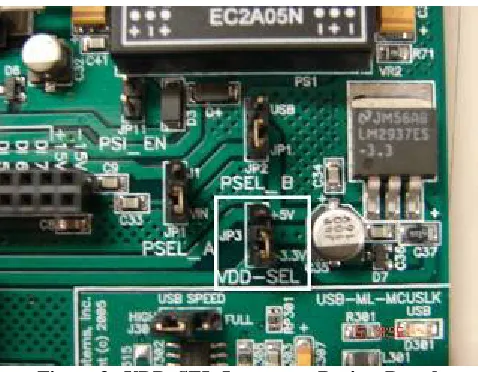
[image:2.612.187.426.461.647.2]Figure 2. The root of the problem is that Vdd can change
between 5V and 3.3V. The LCD only operates with 5V.
3.2 Risks associated with this solution implementation
CAUTION: Please review this section prior to implementing the described solution.
Connecting the +5V to the LCD Vdd (Pin 2 of J13) will also connect to Vdd pins of connector J9, J8
(both LCD ports), U3 (Octal Buffer) and U4 (UART for RS232). This will affect the COMM I/O
signals in that they will be operating at +5V, not Vdd. Most devices should be tolerant of this condition,
however, care and consideration should be accounted for before implementing. Refer to the hardware
manual of any device(s) that will use the COMM signals prior to continuing.
3.3 Solution
At an overview, the solution is to disconnect the VDD supply to the LCD, and re-route it to a constant
5V supply. This will remain unchanged regardless of VDD_SEL configuration. The sections below
will walk you through the steps required in detail.
Step One: Insure that the project board is disconnected from all possible power sources. This includes
the USB connection.
Step Two: Place the Project Board face down (Freescale logo down) on a solid flat surface. See Figure
Figure 4.
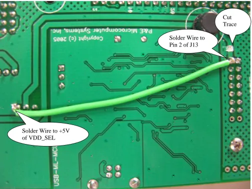
Figure 4. Project Board Face Down (Green Wire is the connection that this document covers)
NOTE:
We recommend cutting the trace close to the J13 pin 2 due to the relative isolation of other nearby
signals. Accidentally, cutting into the nearby ground plane should not pose any significant issues.
Step Five: Perform a continuity check from pin 2 of J13 to the VDD_SEL to verify the trace is cut.
Step Six: Solder a insulated wire from J13 pin 2, to the 5V supply line coming out of VDD_SEL header
on the project board. (Refer to Figure 5)
[image:4.612.58.561.218.596.2]Step Seven: Perform a continuity check to validate your solder connections, and that no nearby
connections have accidentally been bridged.
Figure 5. Zoomed View of Work Area
Solder Wire to
Pin 2 of J13
Solder Wire to +5V
of VDD_SEL
4 Revision History
Version
Date
Revised By
Description of Changes
How to Reach Us:
Home Page:
www.freescale.com
E-mail:
USA/Europe or Locations Not Listed:
Freescale Semiconductor
Technical Information Center, CH370 1300 N. Alma School Road Chandler, Arizona 85224
+1-800-521-6274 or +1-480-768-2130 [email protected]
Europe, Middle East, and Africa:
Freescale Halbleiter Deutschland GmbH Technical Information Center
Schatzbogen 7
81829 Muenchen, Germany +44 1296 380 456 (English) +46 8 52200080 (English) +49 89 92103 559 (German) +33 1 69 35 48 48 (French) [email protected]
Japan
:
Freescale Semiconductor Japan Ltd. Headquarters
ARCO Tower 15F
1-8-1, Shimo-Meguro, Meguro-ku, Tokyo 153-0064, Japan
0120 191014 or +81 3 5437 9125 [email protected]
Asia/Pacific:
Freescale Semiconductor Hong Kong Ltd. Technical Information Center
2 Dai King Street Tai Po Industrial Estate Tai Po, N.T., Hong Kong +800 2666 8080
Information in this document is provided solely to enable system and software implementers to use Freescale Semiconductor products. There are no express or implied copyright licenses granted hereunder to design or fabricate any integrated circuits or integrated circuits based on the information in this document.
Freescale Semiconductor reserves the right to make changes without further notice to any products herein. Freescale Semiconductor makes no warranty, representation or guarantee regarding the suitability of its products for any particular purpose, nor does Freescale Semiconductor assume any liability arising out of the application or use of any product or circuit, and specifically disclaims any and all liability, including without limitation consequential or incidental damages. “Typical” parameters that may be provided in Freescale Semiconductor data sheets and/or specifications can and do vary in different applications and actual performance may vary over time. All operating parameters, including “Typicals”, must be validated for each customer application by customer’s technical experts. Freescale Semiconductor does not convey any license under its patent rights nor the rights of others. Freescale Semiconductor products are not designed, intended, or authorized for use as components in systems intended for surgical implant into the body, or other applications intended to support or sustain life, or for any other application in which the failure of the Freescale Semiconductor product could create a situation where personal injury or death may occur. Should Buyer purchase or use Freescale Semiconductor products for any such unintended or unauthorized application, Buyer shall indemnify and hold Freescale Semiconductor and its officers, employees, subsidiaries, affiliates, and distributors harmless against all claims, costs, damages, and expenses, and reasonable attorney fees arising out of, directly or indirectly, any claim of personal injury or death associated with such unintended or unauthorized use, even if such claim alleges that Freescale Semiconductor was negligent regarding the design or manufacture of the part.
Freescale™ and the Freescale logo are trademarks of Freescale Semiconductor, Inc.