Johnson CC and Taylor LT (1984) Zero dead volumeSow cell for microbore liquid chromatography with Fourier transform infrared spectrometric detection. Analytical Chemistry56: 2642}2647.
Johnson CC, Hellgeth JW and Taylor LT (1985) Reversed-phase liquid chromatography with Fourier transform infrared spectrometric detection using aSow cell inter-face.Analytical Chemistry57: 610}615.
Karmen A (1966) Flame ionization detector for liquid} liquid chromatography. Analytical Chemistry 38: 286}290.
Kuehl D and GrifRths PR (1979) Novel approaches to interfacing a high performance liquid chromatograph with a Fourier transform infrared spectrometer.Journal of Chromatographic Science17: 471}476.
Raynor MW, Bartle KD, Davies IL, Williams A, Clifford AA, Chalmers JM and Cook DW (1988) Polymer
addi-tive characterization by capillary supercritical Suid chromatography/Fourier transform infrared microspec-trometry.Analytical Chemistry60: 427}433.
Sabo M, Gross J, Wang J and Rosenberg IE (1985) On-line high-performance liquid chromatography/Fourier trans-form infrared spectrometry with normal and reverse phases using an attenuated total reSectance Sow cell. Analytical Chemistry57: 1822}1826.
Scott RPW, Scott CG, Munroe M and Hess J Jr. (1974) A transport interface for LC/MS.The Poisoned Patient: The Role of the Laboratory, p. 395. New York: Elsevier. Somsen GW, Hooijschuur EWJ, Goopijer C, Brinkman UATh and Velthorst NH (1996) Coupling of reversed-phase liquid column chromatography and Fourier trans-form infrared spectrometry using post column on-line extraction and solvent elimination. Analytical Chem-istry68: 746}752.
Detectors: Mass Spectrometry
M. R Clench and L. W Tetler,
Sheffield Hallam University, Sheffield, UK
Copyright^ 2000 Academic Press
Introduction
Liquid chromatography (LC) can often separate com-plex mixtures but simple detectors (e.g. ultraviolet-visible UV/Vis) do not allow identiRcation of the individual components. Comparison of retention data and spiking with known standards is normally required to provide evidence of composition but this may lead to erroneous results as absolute identiR ca-tion is not possible. Development of diode array de-tection has somewhat alleviated the problem but not removed it entirely. Absorbance requires the presence of a chromophore in the molecule and, as such, UV/vis spectra do not enable absolute identiRcation but are frequently used to conRrm identity through comparison of recorded spectra with reference spectra. Mass spectrometry (MS) provides a unique means of determining the presence of a compound in a mix-ture by producing a mass spectrum which will aid or conRrm its identiRcation. The relative molar mass (RMM) and/or structurally important information may also be obtained from the mass spectrum.
The combination of a separation technique with MS provides a powerful instrumental method for the analytical scientist. Modern gas chromatography} mass spectrometry (GC-MS) instrumentation, having overcome the obstacles associated with coupling them to each other, has matured into an easy-to-use benchtop technique. The interfacing of high perfor-mance liquid chromatography (HPLC) with a mass
spectrometric detector (LC-MS) poses many prob-lems, not least the different sample requirements of the respective instruments, i.e. liquid and vapour. The purpose of this article is to describe those interfaces that are most routinely used in LC-MS applications and, as such, will cover aspects of ionization methods and, to a lesser extent, mass analysers.
Background
The combination of HPLC and MS can be used as an ofSine technique, that is, fractions are collected and then a mass spectrum of each obtained. Much greater sensitivity, however, may be achieved by having an online interface, but this is much more difRcult to achieve than with GC. The vapourSow in HPLC is much greater than in GC and there may be problems with electrical breakdown in high voltage instru-ments. HPLC may be operated in either normal or reversed-phase modes and the mobile-phase composi-tion may be either isocratic or gradient. Different-sized columns are available (analytical, microbore and capillary), leading to a wide range of operational Sow rates. The various possible conRgurations com-plicate the interfacing to MS.
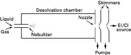
Figure 1 Simplified schematic of a particle beam interface. commercially available have relied on a particular ionization method and this presented limitations to the range of compounds that could be handled. Until the early 1980s, the mainstay ionization techniques were electron ionization (EI) and chemical ionization (CI), both of which required the sample to be in the vapour state. Development of LC-MS was slow, due to problems of matching vacuum requirements with liquidSow. Early interfaces utilized direct liquid in-troduction, usually after splitting the LC eluate. Ther-mal evaporation of the fraction of the liquid taken into the MS was followed by either EI or CI, with the reagent ions being generated from the solvent in the case of CI.
Of the many interfaces that have been reported, those most commonly employed in present applica-tions are based on the following: particle beam (monodisperse aerosol generator interface for chrom-atography or MAGIC), continuous Sow}fast atom bombardment (CF-FAB), thermospray and atmo-spheric pressure ionization.
Ion Formation
Particle Beam
The original particle beam interface was introduced by Willoughby and Browner in the mid-1980s using the acronym MAGIC. It relies on the nebulization of the chromatographic eluent followed by desolvation and then ionization of the resultant microparticles. A schematic of a typical particle beam interface is shown inFigure 1.
The initial nebulization of the eluent is accomp-lished with the aid of a dispersion gas (usually he-lium); thus a Rne and homogeneous aerosol can be generated from mobile-phaseSow rates ranging from 0.1 to 2.0 mL min\1. Several designs of nebulizer are available, some utilizing heat or ultrasound in addi-tion to a gas, to create the aerosol. The resultant mixture of gas and solvent droplets passes directly into a desolvation chamber where the droplets are converted into solvent-free particles before reaching the exit nozzle. To aid faster evaporation of solvent
molecules, the temperature of the chamber is main-tained slightly above ambient. Momentum separation of the resultant stream of gas, solvent vapour and solute microparticles occurs between the desolvation chamber and the ion source. This is achieved by a series of skimmers placed in line with the nebulizer jet and exit nozzle. Differential pumping is effected in the regions between the skimmers. Expansion into the lower pressure regions leads to the formation of a high velocity jet of solute microparticles. Most of the helium and solvent vapours are removed in these lower pressure regions, leading to solute enrichment. The solid solute microparticles enter a conventional EI/CI ion source and are rapidly converted to the gas phase by Sash vaporization upon contact with the heated walls of the source. Subsequent ionization by electron impact or chemical ionization follows.
The particle beam interface offers the advantage of producing library-searchable mass spectra but there are limitations of volatility and thermal stability for the analytes. In common with most LC interfaces for MS, the use of involatile buffers is best avoided, as is the use of mobile phases with a high water content. Disadvantages of the particle beam interface lie in the lack of sensitivity compared to other techniques which rely on ‘soft ionization’ methods, but careful optimization can lead to detection limits in the nano-gram range for full scan acquisitions and use of se-lected ion monitoring can improve this to picograms. The development of particle beam interfaces capable of operating at lower Sow rates would enable an increase in sensitivity to be achieved.
Continuous Flow8Fast Atom Bombardment
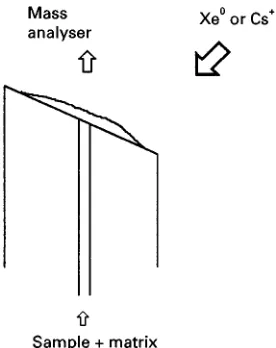
This technique relies on ionization of the sample by FAB. In a FAB ion source the sample is bombarded by a beam of energetic (usually 8 keV) atoms, resulting in the production of ions via the phenomenon of ‘sputtering’. This process, although not fully under-stood, may be viewed as a series of impact cascades through the uppermost layers of the sample, resulting in the ejection of neutral and charged particles from the sample surface. Inert gases (Ar or Xe) are used to produce the atom beam but it is now more usual to employ a beam of fast ions, usually Cs#, with ener-gies up to 30 keV. This latter method is also referred to as liquid secondary ionization mass spectrometry (LSIMS).
Figure 2 CF-FAB probe tip.
vapour pressure. The ion source is normally operated at ambient temperatures and it is therefore possible to obtain mass spectra from thermally labile and/or in-volatile materials. Compounds of RMM up to 2 kDa are routinely analysed by FAB and it is possible to obtain mass spectra from larger molecules. FAB mass spectra generally show abundant ions of the type (M#H)#/(M!H)\, thus allowing RMM informa-tion. These even-electron species are relatively stable and there is not always sufRcient fragmentation to be structurally informative. Chemical noise is often a problem in FAB mass spectra as it may obscure low intensity fragment ions, and peaks arising from the matrix may coincide with sample peaks, hindering interpretation.
CF-FAB (other variations are known as dynamic FAB or frit-FAB) employs either FAB or LSIMS to effect ionization. All rely on the introduction of liquid through a capillary that terminates at the end of a direct insertion probe (Figure 2). Different designs of probe tip have been developed but all require an even spread of liquid over the surface which allows the production of a stable sample ion current. The solution entering the ion source requires the presence of a matrix liquid, normally in the range 1}10% by volume, and this is usually introduced post-column for LC-MS applications. This reduction of the sample/matrix ratio may provide improved signal to chemical noise ratios and peaks associated with the matrix may be either absent or of low intensity. A reduction in the sample suppression effects ob-served in FAB may also result.
This is a very simple interface design and is applic-able to many thermally labile and/or polar samples. The probe tip does require heating (up to 60}703C) to maintain evaporation and prevent freezing due to latent heat of vaporisation. The prime disadvantage is the restriction imposed onSow rates which are in the
range 1}10L min\1 and therefore a split in the column eluent is required for all but capillary col-umns. Splits may be achieved by a number of methods, involving the use of T-pieces, balanced col-umns and pneumatic splitters, either separately or in combination. Whatever method is employed, it should have low dead volume and provide a quick response to changes in solvent composition imposed by gradient elution.
Thermospray
Thermospray ionization is effected directly from a sample solution and may be readily interfaced with HPLC. The thermospray ion source, which was de-veloped from direct liquid introduction interfaces, can accommodate a wide range of liquid Sows (0.5}2.5 mL min\1) but is limited to the use of vol-atile buffers. It is a soft ionization technique and produces mass spectra dominated by ions yielding RMM information, i.e. (M#H)#/(M!H)\, but modiRcations to the source have allowed a certain amount of controlled fragmentation to be induced.
The sample solution is carried into the source via a capillary tube which terminates in a heated block. This results in the formation of a supersonic jet of vapour which contains charged droplets, the charging of the droplets being aided by the presence of a vol-atile electrolyte (e.g. ammonium acetate). By a combi-nation of ion evaporation and ion}molecule reac-tions, sample ions are formed and exit the source via a small sampling oriRce. The excess solvent vapours are removed by a backing rotary pump. In those situations where it is not possible or desirable to add a volatile electrolyte to the mobile phase, ionization may be effected by a mechanism akin to CI. This is achieved either by use of an electron beam (often termedRlament on) or by creating a plasma within the vapour-rich source, usually by a high voltage discharge from a needle } a technique sometimes referred to as a plasmaspray. A simple schematic of a thermospray source is shown inFigure 3.
A wide variety of compounds are amenable to thermospray but its ability to cope with large, non-volatile molecules is poor and the mass range appears to be limited for routine use to compounds below
Figure 3 Simplified diagram of a thermospray ion source.
Figure 4 Ion source for electrospray ionization. For operation in APCI mode, a discharge needle would be placed between the inlet capillary and the counter-electrode.
Lack of fragmentation is often observed in ther-mospray mass spectra but application of a higher voltage to a repeller electrode (located opposite the sampling cone) may be sufRcient to induce the forma-tion of fragment ions.
Criticisms of the technique have centred on the claims of poor reproducibility and compound de-pendence. The performance and optimization of the interface depend on the solution chemistry and solu-tions must be kept free of particulate matter that may lead to blockage of the capillary. Despite some disad-vantages, many applications of thermospray have been described and it has been the mainstay for LC-MS development for a number of years. However, recent advances in alternative ionization methods may well see it superseded as the method of choice for LC-MS.
Atmospheric Pressure Ionization (API) Methods
In the sources so far described, ionization takes place in the vacuum region of the mass spectrometer, thus requiring removal, either through additional pump-ing or by a reduction in the Sow rate of the mobile phase. The production of ions prior to entry to the MS high vacuum regions, i.e. at atmospheric pres-sure, would obviate these requirements. Development of atmospheric pressure ionization techniques has led to a rapid and exciting development in LC-MS instru-mentation. Although API methods have been avail-able for a number of years, it was not until the pioneering work of Fennet al. that their potential was realized. The two variants normally employed in con-junction with HPLC are electrospray ionization (ESI) and atmospheric pressure chemical ionization (APCI).
Electrospray ionization ESI produces charged par-ticles directly from solution at atmospheric pressure. Since its introduction in the mid-1980s it has de-veloped into one of the most popular ionization tech-niques, especially for biomolecules. The source design is relatively simple and extraction of ions into the mass spectrometer is readily achieved. Although a variety of source designs have been developed and commercial instruments differ in this respect, the
basic processes of ion information and extraction are similar.
In its simplest form, ESI is realized from a sample solution (Sow rate 2}10L min\1) introduced through a capillary into the ion source, which is at atmospheric pressure. The emerging liquid is formed into aRne spray of charged droplets by the presence of a potential difference of $3}5 kV applied be-tween the capillary and a counter-electrode. The formation of gaseous ions from the sample solution occurs as a result of this droplet formation and sub-sequent desolvation. Formation of the charged drop-lets is reasonably well understood, but the process of ion formation from them is the subject of debate.
A typical source is shown inFigure 4.
The capillary delivering the liquid Sow is con-tained, in a co-axial arrangement, within an outer stainless-steel capillary. A Sow of gas through this outer capillary aids droplet formation and extends the usableSow rate up to&1.5 mL min\1. Nitrogen is the usual nebulizing gas employed in this modiR ca-tion, sometimes referred to as ion spray. Beyond the counterelectrode is a sampling cone (or in some in-struments this may be a short glass or steel capillary) which may be maintained at a low voltage (&30}250 V). Between this cone and the counterelec-trode, a countercurrentSow of gas (usually nitrogen) is introduced. This gas, known as the drying or cur-tain gas, aids the desolvation process. Additionally, the source may be held at elevated temperatures (&603C) as a further means of helping desolvation. Entry into the analyser region of the mass spectrom-eter proceeds via a skimmer held at ground potential. Stages of differential pumping (or cryopumping) re-duce the source pressure (atmospheric) to that of the analyser (&10\5mmHg).
[image:4.568.289.520.521.676.2]representa-Figure 5 (A) ESI mass spectrum of cytochromec; (B) deconvoluted mass spectrum of cytochrome c. tive of the intact molecule with virtually no
frag-mentation. For small molecules the mass spectra have a very simple appearance, generally showing just the protonated molecule ion and/or adduct ions, e.g. (M#Na)#. The mass spectra of larger molecules, however, become more complicated because of the production of multiply charged ions. A series of molecule ions of the form (M#nH#)n#is produced, wherenvaries according to the number of sites on the molecule which are able to accept a proton. The molecular mass of a compound is calculated from the ion series by a deconvolution algorithm contained in the instrument’s software (though it can be done manually!). An example of a typical ESI spectrum and the result of deconvolution is shown in Figure 5.
Formation of negative ions occurs in electrospray, with both singly and multiply charged species being formed. The choice of ionization mode depends on the proton afRnities of the analytes.
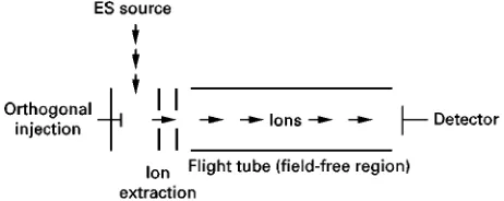
[image:5.568.131.442.262.466.2]Figure 6 Schematic of a time-of-fight mass analyser with an orthogonal ESI source.
Since its introduction, ESI has undergone rapid development and has seen widespread application, especially in the biochemical Reld. Commercial in-struments with dedicated ESI sources are readily available, ranging from simple benchtops to sophisti-cated tandem mass spectrometers.
The development of orthogonal sources has allowed the use of non-volatile buffers for LC-MS whereas ‘in-line’ sources are restricted to volatile buffers.
Atmospheric pressure chemical ionization An APCI source relies on the formation of reactant ions and their subsequent reaction with sample molecules. These reactant ions are formed at atmospheric pres-sure by a corona discharge achieved by maintaining a stainless-steel needle at a voltage of 3}6 kV. The source design for APCI, for LC-MS, is very similar to that of ESI, the major difference being the addition of the discharge needle in the region between inlet capil-lary and the counterelectrode. The LC eluent is con-verted into a Rne droplet spray by a nebulizing gas and this is followed by vaporization in a heated re-gion (up to 5003C, depending on the instrument) of the capillary. This rapid desolvation and vaporization minimizes any thermal decomposition. Chemical ion-ization of the sample is effected via ion molecule reactions: the reactant ions are formed from the LC mobile phase. Operation in either positive ion or negative ion mode is possible depending on the nature of the analyte. The use of a curtain gas aids decluster-ing in a manner similar to electrospray. Molecular weight information is readily provided, but to obtain structural information the use of collision induced decomposition (CID) experiments is required.
Mobile phaseSows from 0.1 to 2.0 mL min\1can be accommodated, eliminating the need for splitting. Both volatile and, with the advent of orthogonal sources, nonvolatile buffers are tolerated and mobile-phase compositions of up to 100% water are permitted.
Mass Analysis
All the above ionization techniques may be used in conjunction with different types of mass analyser, though the use of single or multistage quadrupoles is most common. The reader is referred to the chapter on GC-MS for a discussion of sector and quadrupole analysers.
Ion traps, time-of-Sight and ion cyclotron reson-ance mass spectrometers have all been used in LC-MS instruments: a full treatment of them is beyond the scope of this article.
The ion trap is a device in which ions may be stored and consecutive experiments carried out upon them, i.e. mass spectrometry in time rather than space. Ions
may be produced directly in the trap, e.g. by EI (GC-MS) or they may be injected from an external source, e.g. ESI. Technological developments have ensured continued improvement to the mass range and resolution. The ability to undertake sequential CID experiments is a powerful feature of modern instruments. Dedicated LC-MS instruments employ-ing ion traps in conjunction with ESI and APCI are now available.
Time-of-Sight analysers are particularly well suited to pulsed ion sources, e.g. matrix-assisted laser de-sorption ionization (MALDI) and offer increased sen-sitivity over scanning instruments. Recently, pulsed orthogonal electrospray sources have been described in conjunction with time-of-Sight.
Instruments relying on ion cyclotron resonance (ICR) employ Fourier transform techniques and FT-ICR mass spectrometers are capable of achieving very high resolution. They require low pressures (&UHV) to operate effectively and the magneticRelds used are generated by super-conducting magnets. Ions, which may be formed directly within the ICR cell or injected from an external source (e.g. ESI, MALDI), are excit-ed using a broad-band radiofrequency sweep and their cyclical motion induces an image current. This time domain signal is readily transformed to a mass spectrum by a Fourier transform. The very high res-olution obtainable from this method of mass analysis enables separation of the isotopic peaks for each of the charge states resulting from ESI. This offers an advantage in the assignment of values ofm andzin ESI mass spectra containing several masses.
Tandem Mass Spectrometry
Of the ionization techniques described, only the particle beam method produces sufRcient fragmentation to give structural information. The softer ionization methods allow for RMM determination from either protonated molecule ions and/or adduct species, with little or no structural information being available owing to lack of fragmentation. It is possible to in-duce some degree of fragmentation in both thermos-pray and API sources by manipulating the source conditions. A more speciRc means of promoting frag-mentation involves the use of sequential mass analy-sis, i.e. the isolation of a precursor ion followed by its interaction with a target gas to induce fragmentation by collisional activation, thus allowing a product ion mass spectrum to be recorded. This and other types of CID experiments can be carried out in time, in an ion storage device or in space using scanning or time-of-Sight instruments. For a full discussion of the instru-ments and experiinstru-ments possible, the reader is referred to the Further Reading section.
The most commonly used type of tandem mass spectrometer is the triple quadrupole, and benchtop instruments of this type with a dedicated LC interface are commercially available. They are relatively easy to use and offer a range of MS-MS scans. In addition to the product ion scan and the reaction monitoring scan (both MS1 and MS2 operate in selected ion mode), two other scan modes are available} precur-sor ion and constant neutral loss. In the former, MS1 is scanned whilst MS2 is set to pass a speciRc ion, thus yielding information as to the origins of a speciRc fragment ion. This may be employed to identify those components of a mixture which contain a common functional group, e.g. sulfonated compounds will typ-ically fragment to give an ion at m/z80 (SO\3) in negative ion mode; thus a precursor ion scan of this
ion should be speciRc for the presence of sulfonates. Neutral loss scans involve scanning both MS1 and MS2, but with the respective mass ranges offset by the mass of the neutral species.
Conclusion
This article has attempted to review the present situ-ation with regards to the interfacing of LC to MS. LC-MS is now developing into a mature technique and modern instrumentation allows for routine and robust operation. Further developments will un-doubtedly take place, with API and PB techniques to the forefront. The introduction of cheaper and easier-to-use benchtop instruments will promote continued expansion in the applications of this extremely powerful analytical method.
See also: III/Drugs and Metabolites: Liquid Chromato-graphy}Mass Spectrometry. Pharmaceuticals: Chrom-atographic Separations.
Further Reading
Bruins AP (1998) Mechanistic aspects of electrospray ionisation.Journal of Chromatography A794: 345. Busch KL, Glish GL and McLuckey SA (1988)Mass
Spec-trometry/Mass Spectrometry. New York: VCH Cappiello A (1996) Is particle beam an up-to-date LC-MS
interface.Mass Spectrometry Reviews15: 283. Chapman JR (1993)Practical Organic Mass Spectrometry
2ndedn. Chichester: John Wiley.
Chernushevich IV, Ens W and Standing KG (1999) Ortho-gonal-injection TOFMS for analysing biomolecules. Analytical Chemistry71: 453A.
Cole RB (ed.) (1997)Electrospray Ionisation Mass Spectro-metry: Fundamentals, Instrumentation and Applica-tions. New York: Wiley-Interscience.
Fenn JB, Mann M, Meng CK and Wong SF (1990) Electro-spray ionisation}principles and practice.Mass Spectro-metry Reviews9: 37.
Matsuo T, Caprioli RM, Gross ML and Seyama Y (eds.) (1994)Biological Mass Spectrometry: Present and Fu-ture. Chichester: John Wiley.
Niessen WMA (1998) Advances in instrumentation in liquid chromatography-mass spectrometry and related liquid-introduction Techniques.Journal of Chromatog-raphy A794: 407.
Niessen WMA, Tjaden UR and Van Der Greef J (1991) Strategies in developing interfaces for coupling liquid-chromatography and mass-spectrometry. Journal of Chromatography554: 3.
Willoughby RC and Browner RF (1984) Monodisperse aerosol generation interface for combining liquid-chromatography with mass spectroscopy. Analytical Chemistry56: 2626.
Willoughby R, Sheehan E and Mitrovich S (1998)A Global View of LC-MS. Pittsburgh: Global View.