sometimes co-occurs with deoxynivalenol. Zeara-lenone can be extracted from grain with chloroform and cleaned up using a silica gel column, followed by defatting by partitioning between hexane and acetonitrile. For TLC the samples and standards are dissolved in benzene and spotted on a silica gel and developed with ethanol}chloroform (5 : 95 v/v) or acetic acid}benzene (5 : 95 v/v). Under 254 nm ultra-violet light, zearalenone appears as a greenish-blue Suorescent spot at RF"0.5. If the plate is sprayed with an aluminium chloride solution and heated for 5 min at 1303C, zearalenone will appear under 365 nm ultraviolet light as a blue Suorescent spot.
Summary
TLC methods have been developed to analyse for a variety of mycotoxins in the commodities in which they occur. TLC densitometric determinations pro-vide precise quantitative data at ng g\1 to g g\1 levels. The major advantages of TLC over LC are its low cost and its use as a screening tool. The commercial availability of precoated TLC plates, including silica gel, reversed-phase and high perfor-mance plates has resulted in expanded applications in the mycotoxinReld. The role of TLC in the analysis of mycotoxins will continue for the foreseeable future.
See also: II/ Chromatography: Thin-Layer (Planar): Historical Development; Preparative Thin-Layer (Planar)
Chromatography. III/Aflatoxins and Mycotoxins: Chrom-atography. Immunoaffinity Extraction.
Further Reading
Bullerman LB and Draughon FA (eds) (1994) Fusarium moniliforme and Fumonisin symposium. Journal of Food Protection57: 513}546.
Cole RJ and Cox RH (eds) (1981)Handbook of Toxic Fungal Metabolites. New York: Academic Press. Eaton DE and Groopman JD (eds) (1994)The Toxicology
of AUatoxins. San Diego: Academic Press.
Purchase IFH (ed.) (1974)Mycotoxins. Amsterdam: Elsevier. Rodricks JV (ed.) (1976) Mycotoxins and Other Fungal Related Food Problems. Advances in Chemistry Series 149. Washington, DC: American Chemical Society. Rodricks JV, Hesseltine CW and Mehlman MA (eds)
(1977)Mycotoxins in Human and Animal Health. Park Forest South, IL: Pathotox.
Scott PM (ed.) (1995) Chapter 49, Natural toxins. In: Cunniff P (ed.) OfTcial Methods of Analysis of AOAC International, 16th edn., Gaithersburg. MD: AOAC International.
Stack, ME (1996) Toxins. In: Sherma J and Fried B (eds)
Handbook of Thin-layer Chromatography. New York: Marcel Decker.
Steyn PS (ed.) (1980) The Biosynthesis of Myco-toxins. New York: Academic Press.
Touchstone JC (ed.) (1982) Advances in Thin Layer Chromatography. New York: Wiley.
Whitaker TB, Springer J, DeRze PRet al. (1995) Evaluation of sampling plans used in the United States, United Kingdom, and the Netherlands to test raw shelled pea-nuts for aSatoxin. Journal of AOAC International78: 1010}1018.
AIR LIQUEFACTION: DISTILLATION
R. Agrawal and D. M. Herron, Air Products
and Chemicals, Hamilton Boulevard, Allentown, PA, USA
Copyright^ 2000 Air Products and Chemicals, Inc
Oxygen, nitrogen and argon, the major components of air, have been separated by distillation at cryogenic temperatures for nearly a century. Air was commer-cially liqueRed as early as 1895 by Carl von Linde and also by William Hampson. Linde separated oxygen from air by distillation in a single column in 1902. A commercial plant producing pure nitrogen was already in operation by 1904. The Rrst
double-col-umn distillation system, the predecessor to current double-column processes, was commissioned in 1910 by Linde. Argon was produced on an industrial scale by 1913. Today the major industrial companies sup-plying products from air distillation and liquefaction and also the equipment for this purpose are: AGA, Air Liquide, Air Products and Chemicals, the BOC Group, Linde, Messer Group, Nippon Sanso and Praxair.
Table 1 Composition of air and thermodynamic properties of its constituent gases
Constituent gas Concentration
(mol%)
Boiling temperature (3C)a
Critical temperature (3C)
Nitrogen 78.12 !195.8 !146.9
Oxygen 20.95 !182.9 !118.8
Argon 0.93 !185.9 !122.4
Neon 18 p.p.m. !246.1 !228.8
Helium 5.3 p.p.m. !268.9 !267.9
Krypton 1.1 p.p.m. !153.4 !63.8
Xenon 0.08 p.p.m. !108.1 !16.6
aBoiling temperature at 101.3 kPa.
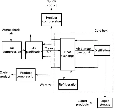
Figure 1 Basic steps in a cryogenic air distillation plant.
a wide range of industrial and medical applications. Typical industries using these gases include: ferrous and nonferrous metals, chemicals, petroleum, food, paper, glass, textile and electronics. Oxygen is gener-ally used as an oxidant while nitrogen and argon are used to provide inert atmospheres. Krypton is used in light bulbs, lasers, sputtering of electronic compo-nents and high energy physics. Neon is used inS uor-escent lighting, infrared detection equipment and ex-perimental physics at cryogenic temperatures. Xenon is used in electronicSashlights, as an anaesthetic and in a new application where an on-board xenon ion propulsion system is used for positioning a satellite. Helium is not generally recovered from air due to its low concentration.
The history of air distillation started with oxygen production followed by recovery of other constitu-ents. Therefore, the distillation processes to produce oxygen are describedRrst here followed by argon and then nitrogen. These topics are followed by liquefac-tion processes andRnally a brief description is given of the major equipment used in cryogenic air separ-ation and liquefaction processes.
Distillation
Distillation of Air to Recover Oxygen
Figure 2 A single column to produce oxygen.
Air isRrst compressed in a multistage compressor and cooled to near ambient temperature. Given the boiling point temperatures of nitrogen and oxygen in Table 1, it is clear that air has to be cooled to ex-tremely low temperatures before it can be distilled. It follows that a number of impurities present in air and which would freeze at such cryogenic temperatures must be removed to avoid plugging of heat exchange and separation equipment. Typical impurities that are not listed in Table 1 but are present in air include: water (after compression air is saturated); carbon dioxide (about 375 p.p.m.); hydrocarbons such as acetylene (0.1}1 p.p.m.), methane (2}10 p.p.m.) and some higher hydrocarbons in varying concentrations (ethylene, propylene, ethane, etc.); carbon monoxide; nitrogen oxides and sulfur compounds. Therefore, in the second step, compressed air is sent through a puri-Rcation system at least to remove impurities such as water, carbon dioxide, acetylene, nitrogen oxides and sulfur compounds.
In the third step, the compressed and cleaned air is cooled to near its dewpoint by heat exchange. Finally, the cooled air is sent to an appropriate distillation column system. Here air is distilled into at least two product steams } one stream is enriched in oxygen and the other is enriched in nitrogen. Both of these streams are then warmed to near ambient temper-ature by countercurrent heat exchange with the in-coming air. When a product stream is required at a higher pressure, it is further compressed. Liquid products such as liquid oxygen, liquid nitrogen or liquid argon can also be produced from the distilla-tion column system and sent to liquid storage for later distribution.
The heat exchanger and the distillation system are enclosed in a well-insulated enclosure called the cold box. Despite the insulation, there is heat leakage and therefore, refrigeration is provided to the cold box to keep the inside equipment cold. For this purpose, modern cryogenic plants employ turbo-expanders that are also enclosed in the cold box. These turbo-expan-ders produce work out of the cold box and keep all the equipment at the desired cryogenic temperatures. Now that the basic steps that are common to all the air distillation plants have been described, attention will be paid to the distillation of air after it is cooled to near its dewpoint temperature. The distillation of air is at the heart of an air separation plant and its arrangement varies with the number, quantity and purity of products being produced.
The early developments in air distillation to pro-duce oxygen were propelled by the invention of the oxyacetylene blow torch for welding and steel cut-ting. In 1902, Carl von Linde introduced theRrst air distillation process using a single distillation column.
A simpliRed sketch of this single column arrangement is shown inFigure 2.
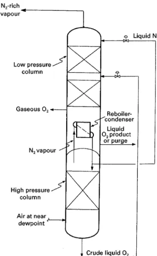
Figure 3 A double-column arrangement to produce oxygen.
ambient temperature by heat exchange against the incoming air stream (Figure 1). While the early plants produced oxygen at a purity of 80}90%, the single-column process can provide oxygen at any desired higher purity. Generally, the purity of oxygen used in metal welding and cutting is 99.5% or greater.
The problem with the single distillation column process shown in Figure 2 is that the recovery of oxygen is low. The reason is that the minimum con-centration of oxygen in the nitrogen-rich vapour stream leaving the top of the distillation column is limited to that value which is in equilibrium with the liquid air that is fed at the top. Since the concentra-tion of oxygen in air is fairly high, a sizeable fracconcentra-tion of the oxygen in the feed air leaves in the nitrogen-rich vapour stream. To illustrate this for a distillation column operating at 1.4 atm and producing 99.5% oxygen, the pressure of feed air is about 5 atm and a vapour stream in thermodynamic equilibrium with the liquid air stream (at 1.4 atm) will be 6.9% oxy-gen. A typical oxygen recovery from such a distilla-tion column would only be in the neighbourhood of 14 mol of oxygen per 100 mol of feed air.
It is clear that, for higher recoveries of oxygen, the concentration of oxygen in the nitrogen-rich vapour stream leaving the top of the distillation column must be low. In other words, both product streams should be relatively pure. This requires that the liquid reSux to the top of the distillation column should also be relatively pure. It seems that Georges Claude was the Rrst to provide the solution by using his dephlegma-tion equipment in 1903. However, it was Carl von Linde’s double distillation column of 1910 that revol-utionized the industry and is still the workhorse of the modern cryogenic oxygen plants.
A typical double distillation column conRguration is shown inFigure 3.
In this arrangement, compressed, cleaned and cooled air is now sent to a high pressure distillation column that operates at about 6 atm. As the vapour rises up this high pressure column, it is enriched in nitrogen and at the top of the column, the concentra-tion of oxygen has been reduced to an extremely low level. The nitrogen vapour is condensed by heat ex-change in a reboiler-condenser. Of this condensed nitrogen stream, about 60% is returned back to the top of the high pressure column as liquid reSux; approximately 40% of the Sow is sent to the top of a low pressure column that operates at around 1.4 atm. The liquid descending the high pressure col-umn becomes enriched in oxygen to produce crude liquid oxygen leaving the bottom (typically around 35% oxygen). This crude liquid oxygen is reduced in pressure across a valve and fed to an intermediate location in the low pressure column. In the low
pres-sure column, crude liquid oxygen is distilled to pro-duce a nitrogen-rich vapour stream at the top and an oxygen product stream at the bottom. The boil-up at the bottom of the low pressure column is provided by vaporizing the liquid oxygen stream in the sump by heat exchange against the condensing nitrogen vapour stream from the top of the high pressure column. A portion of the vapour from the reboiler-condenser is recovered as gaseous oxygen product while the rest rises to perform distillation in the low pressure column. When needed, some liquid oxygen can also be recovered from the sump as product.
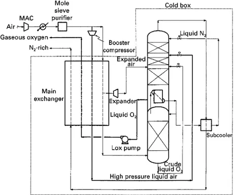
Figure 4 Pumped liquid oxygen flowsheet.
often be reduced to p.p.m. level. Therefore, the con-centration of oxygen in the nitrogen-rich vapour stream from the top of the low pressure column is reduced to extremely low levels. This not only allows the potential to recover the nitrogen-rich vapour stream as a useful product stream, but also makes very high recoveries of oxygen possible. For a double-column process, production of 99.5% oxygen in ex-cess of 20.5 mol per 100 mol of feed air (maximum oxygen content being 20.95 mol) is quite common.
For most uses, gaseous oxygen is needed at sures greater than atmospheric pressure. This pres-sure can range from about 2 atm absolute prespres-sure for glass-making to pressures in the range of 30}80 atm for the gasiRcation of hydrocarbons such as coal and petroleum residuum. One obvious method to deliver pressurized oxygen is to compress gaseous oxygen to the desired pressure after it exits the cold box. However, safety considerations tend to make the equipment associated with oxygen com-pressors expensive. In certain applications, where both oxygen and nitrogen are needed at higher pres-sures, one has the option of increasing the pressure of the distillation columns and directly produce both products at elevated pressures. Unfortunately, the low pressure column is seldom operated at pressures greater than 8 atm absolute. This is because the pres-sure of the high prespres-sure column is typically greater than two to three times the pressure of the low pres-sure column and distillation in the high prespres-sure
col-umn must be conducted at a pressure that is sufR -ciently lower than the critical pressures of nitrogen and oxygen. A third method that is becoming more popular is the use of a pumped liquid oxygen process. This method is also sometimes referred as internal oxygen compression. A schematic of such a plant is shown inFigure 4.
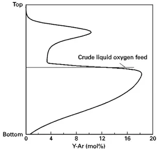
Figure 5 Vapour-phase composition in the low pressure column.
This increases the fraction of liquid in this stream as its pressure is reduced to that of the low pressure column. This technique, which is commonly used in any oxygen plant to increase liquid nitrogen reSux to the low pressure column, has the beneRcial effect of increasing the purity and recovery of products.
The second major difference is the withdrawal of oxygen product from the low pressure column as liquid and its subsequent vaporization. The liquid oxygen is pumped in a liquid oxygen pump to the desired oxygen product pressure. This pumped liquid oxygen is then vaporized in the main heat exchanger. In order to maintain refrigeration balance, it is essen-tial that another stream be condensed through heat exchange as the pumped liquid oxygen is being va-porized. For this purpose, about 30% of the cleaned air is further boosted to a higher pressure in a booster compressor. The pressure of the boosted air is chosen such that it would easily condense through heat ex-change with the vaporizing oxygen stream. Generally the pressure of the condensing air stream is much greater than the oxygen stream. The condensed liquid air from the main heat exchanger is appropriately fed to either one or both of the distillation columns. The warmed gaseous oxygen stream provides the desired pressurized oxygen product.
While the early oxygen plants produced only a few tons of oxygen per day, modern plants are capable of producing in excess of 3000 tons per day of oxygen in a single train.
Distillation of Air to Recover Argon
After nitrogen and oxygen, argon is the most abundant component in air. Its inert property is quite attractive for metals and several other material-processing applications. Within a very short time of the discovery of the double-column system, argon was distilled from air in 1913. The distillation ar-rangement to produce argon in modern plants was generally described in a German patent by 1935.
The arrangement for argon production starts with an examination of the argon concentration proRle in the low pressure column of a double-column process. From the normal boiling temperatures listed in Table 1, it is readily observed that the volatility of argon is between that of nitrogen and oxygen and, furthermore, it is closer to oxygen than nitrogen. As a result, the concentration of argon in the liquid nitrogen stream from the high pressure column (Fig-ures 3 and 4) is at p.p.m. level and virtually all the argon is contained in the crude liquid oxygen. There-fore, the bulk of the argon in air enters at an inter-mediate point on the low pressure column. When oxygen containing less than 0.5% argon is produced, argon is forced to escape from the top of the low
pressure column in the nitrogen-rich vapour stream. However, the liquid nitrogen reSux stream is virtually free of argon and tends to drive argon down the low pressure column. Consequently, the concentration of argon in the vapour phase at an intermediate location between the crude LOX feed and the oxygen product withdrawal point reaches levels approaching 20%. A typical vapour-phase argon concentration proRle in the low pressure column is shown inFigure 5. The build-up of argon provides an opportunity to with-draw a side vapour stream from near the location where a peak in argon concentration occurs and to distil it further in a side distillation column to pro-duce concentrated argon.
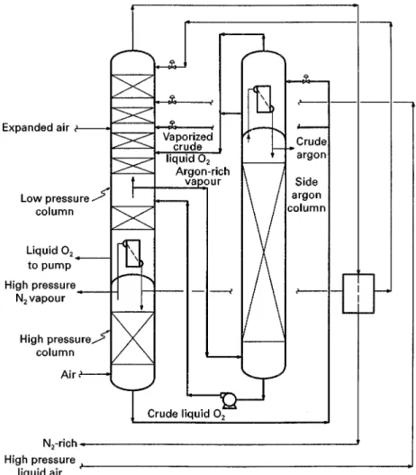
Figure 6 Distillation arrangement for argon separation from air for the process shown in Figure 4.
pumped back to the argon-rich vapour draw location of the low pressure column. Condensation at the top of the side argon column is provided by boiling a por-tion of the crude liquid oxygen at nearly the low pressure column pressure, as shown in Figure 6. The vaporized crude liquid oxygen stream is fed to the low pressure column a few stages of separation below the location where the unboiled crude liquid oxygen is fed. The recovery of argon from cryogenic air is easily in the range of 70}85% and occasionally, if needed, it can be as high as 95% of the total argon contained in the feed air.
While the concentration of oxygen in the crude argon recovered from the arrangement in Figure 6 is below 5}100 p.p.m., the nitrogen concentration is much higher, as nearly all the nitrogen contained in the argon-rich vapour stream shows up in the crude argon. Generally, the argon product speciRcation re-quires that the nitrogen concentration also be below 5 p.p.m. Therefore, the crude argon stream is sub-sequently distilled in a pure argon column with separ-ation stages both below and above the feed. Boil-up and condensing duties for this column are extremely
low and are easily provided by using side streams that are withdrawn from one or more appropriate process streams, shown inFigure 6, such as crude liquid oxy-gen, high pressure liquid air or high pressure nitrogen vapour. A waste vapour stream containing all the nitrogen is withdrawn from the top of the pure argon column and pure liquid argon product is collected and sent to a storage tank from the bottom of this column.
Distillation of Air to Recover Nitrogen
Figure 7 A single distillation column process for nitrogen production.
of the low pressure column can also be recovered as a useful product.
In the 1960s industrial demand for nitrogen in-creased, and this led to a need for plants that were designed solely for nitrogen with no co-production of oxygen. For most applications, nitrogen product is required at a pressure between 6 and 10 atm. There are two basic schemes for nitrogen separation from air: one uses a single column while the other uses two columns (similar to the double-column process for oxygen production). The single-column process is used for relatively small size nitrogen plants (up to about 500 tons per day of nitrogen) and two-column processes are used for larger size plants. Cold boxes can now be designed to produce as much as 10 000 tons per day of nitrogen in a single train.
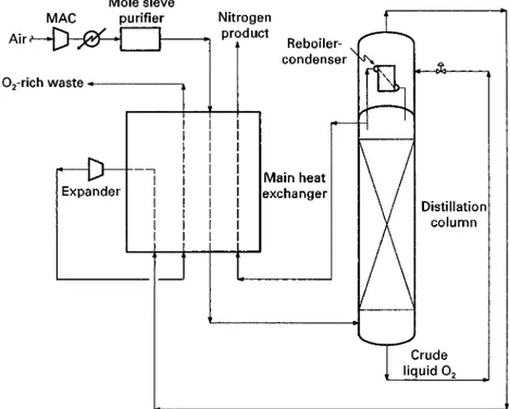
A single-column process for nitrogen separation is shown inFigure 7.
Feed air is compressed to a pressure in excess of about 5 atm absolute, cleaned of impurities in the molecular sieve puriRer and cooled to near its dew-point in the main heat exchanger by heat exchange against the returning streams. The cooled air stream is then fed to the bottom of a single column. SufR -cient separation stages are used in this column to attain the desired purity at the top of this column. A portion of the nitrogen vapour from the top is withdrawn and warmed in the main heat exchanger to provide the desired nitrogen product. The rest of
the nitrogen vapour stream is condensed in a reboiler-condenser and returned as reSux to the column. The ratio of liquid to vapourSow rates in the column is in the neighbourhood of 0.6. The crude liquid oxygen stream from the bottom of the column is reduced in pressure and vaporized in the reboiler-condenser. The vaporized stream is partially warmed in the main heat exchanger and then expanded in a turbo-expander to near atmospheric pressure to provide the needed refrigeration for the plant. The expanded stream is then warmed to near ambient temperature in the main heat exchanger and eventual-ly discharged as an oxygen-rich waste stream. The concentration of oxygen in the waste stream is ap-proximately 35%. TheSow rate of the nitrogen prod-uct stream is about 40}50 mol per 100 mol of the feed air.
The main problem with the single-column process is that the crude liquid oxygen leaving from the bot-tom of the column is at best, in thermodynamic equi-librium with the feed air. This means that there is a lower limit to the concentration of nitrogen in the crude liquid oxygen stream. This limits the recovery of nitrogen. For higher recoveries of nitrogen and more efRcient processes, it is essential that the crude liquid oxygen stream be further distilled to recover the contained nitrogen.Figure 8shows such a two-column process.
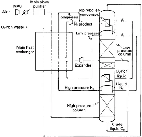
Figure 8 A two-column process fo nitrogen production.
crude liquid oxygen from the bottom of the high pressure column is fed to an intermediate location of a low pressure column for further distillation. A low pressure nitrogen vapour stream is recovered from the top of the low pressure column as a second prod-uct stream. Another portion of this low pressure nitrogen stream is condensed in the top reboiler-condenser and returned as the major reSux stream to the top of the low pressure column. Optionally, a mi-nor nitrogen reSux stream can also be provided to the low pressure column from the high pressure column. An oxygen-rich liquid stream containing about 70% oxygen is withdrawn from the bottom of the low pressure column, reduced in pressure and vaporized in the top reboiler-condenser. The vaporized stream is then warmed in the main heat exchanger and event-ually discarded as a waste stream. Note that the refrigeration for the plant is met by expanding a por-tion of the gaseous feed air stream to the low pressure column in a turbo-expander. In this process, the feed air is compressed to about 8}9 atm absolute and the pressure of the low pressure column is about 3 atm absolute. A nitrogen compressor is generally used to compress the low pressure nitrogen product stream and then it is combined with the high pressure nitro-gen product stream. The typical Sow rate of the
combined nitrogen product stream is about 72 mol per 100 mol of the feed air stream. This two-column nitrogen generator and its variations are particularly attractive for enhanced oil recovery where a very large quantity of nitrogen is injected in the wells to maintain pressure.
Ultrahigh Purity Nitrogen and Oxygen Production for the Semiconductor Industry
The fast-growing semiconductor industry uses bulk nitrogen and oxygen gases in the manufacturing of computer chips. The acceptable level of impurities in the supply of these bulk gases has been continually declining over the last decade. Currently, impurities are limited to few parts per billion (p.p.b.) and levels are expected to drop down to parts per trillion levels as wafer sizes increase. The cryogenic distillation pro-cess is the only known method of present that, in conjuction with other adsorption and catalytic pro-cesses, can meet the stringent demands of ultrahigh purity (UHP) gases.
Figure 9 A UHP nitrogen scheme.
impurities that are heavier than oxygen } methane and higher hydrocarbons and nitrogen oxides are all present in p.p.m. concentrations. When nitrogen is distilled in one of the typical processes discussed earlier, it contains almost all the hydrogen, helium and neon and a major fraction of the carbon monox-ide contained in the air. Similarly, a typical high purity oxygen contains all the unacceptable heavier impurities } krypton, xenon, methane and higher hydrocarbons, for example. Clearly the conventional distillation methods need modiRcation to be able to supply the UHP gases.
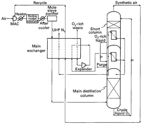
One early method used to produce UHP nitrogen was to pass the nitrogen from a typical cryogenic distillation process over a bed of a nickel supported on silica to remove the trace levels of oxygen, hydro-gen and carbon monoxide. This method is now used for back-up systems since the regular supply of UHP nitrogen is produced directly from the cold box. One distillation scheme to produce UHP nitrogen is shown inFigure 9.
The feed air is compressed to a pressure that is slightly greater than the pressure at which UHP nitro-gen is required. This is done to supply the UHP nitrogen product directly from the cold box to the semiconductor fabrication plant without any further compression. The pressure of the supply UHP nitro-gen is nitro-generally 8}10 atm absolute. The feed air after compression is heated to a temperature of about
2003C and passed over a noble metal catalyst such as platinum to oxidize all the carbon monoxide and hydrogen. The exhaust gas is then cooled and passed through the molecular sieve unit. In an alternative process, a separate noble metal catalyst is not used but instead, layers of adsorbent catalysts are supplied within the molecular sieve unit to remove hydrogen and carbon monoxide to p.p.b. level. The impurities-free air is then cooled in the main heat exchanger and distilled in a column similar to the one shown in Figure 7. A large number of separation stages (60}100) are used in this main distillation column to reduce the oxygen concentration in the resulting nitrogen product stream to a level of a few p.p.b.
the pressure energy, this stream is recycled after further boosting its pressure to that of the main distillation column. InFigure 9, synthetic air is fed to an interstage of the main air compressor. This conR g-uration saves the capital cost associated with a separ-ate booster recycle compressor.
Not all the liquid at the bottom of the short column is vaporized; instead, an oxygen-rich liquid contain-ing about 60}70% oxygen is withdrawn. The pres-sure of this liquid is reduced by 1}2 atm and then it is vaporized in a separate reboiler-condenser to produce another portion of the liquid nitrogen reSux for the main distillation column. A liquid purge stream is taken from this reboiler to prevent the accumulation of hydrocarbons to unsafe levels. The vaporized oxy-gen-rich stream is then expanded to provide the needed refrigeration for the plant and is eventually discharged as a waste stream.
The reason for modifying the distillation scheme of Figure 7to that ofFigure 9stems from the fact that, in a UHP nitrogen process, the distillation pressure is quite high. In Figure 7, high pressure distillation causes the waste stream to vaporize in the reboiler-condenser at a pressure greater than 4 atm. When a large portion of the feed air (in this case 60%) is sent to the turbo-expander at such a high pressure, excess refrigeration is produced. The consequence is that the pressure energy of the waste stream is not utilized effectively and the process becomes inef-Rcient. In constrast, the UHP nitrogen distillation scheme inFigure 9recovers nearly half of the crude liquid oxygen stream as a recycle synthetic air stream, thereby reducing the Sow to the turbo-expander. In other words, the production of excess refrigeration is avoided and efRcient operation is maintained by sending only that portion of the crude liquid oxygen stream needed for the refrigeration to the turbo-expander.
There are several other distillation schemes used for the production of UHP nitrogen. However, all the efRcient schemes are based on modiR ca-tion of the scheme in Figure 7, such as is shown in Figure 9.
Generally, UHP oxygen is required in much smaller quantities (generally 1}5% of the UHP nitrogen pro-duction rate). It is essential that not only the concen-tration of a lighter impurity such as argon be in the p.p.m. to p.p.b. level but also that the concentration of heavier impurities, such as krypton, xenon and hydrocarbons, be no more than a few p.p.b. in the UHP oxygen stream. In contrast to this, a standard-grade oxygen from the process shown in Figure 4 contains about 0.5% argon and all of the heavier impurities such as methane, krypton and xenon are contained in the feed air.
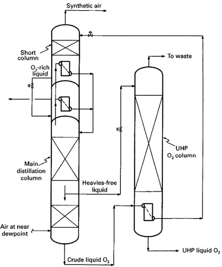
A UHP oxygen distillation scheme that is a modiR -cation to the distillation conRguration of Figure 9 is shown inFigure 10.
This modiRcation results from an observation that, as the feed air ascends the main distillation column, all the impurities that are heavier than oxygen are rapidly reduced to nearly zero within a few separ-ation stages. The concentrsepar-ation of oxygen, however, is still at signiRcant levels. Thus, a heavies-free liquid stream is withdrawn from about 10}15 separation stages above the vapour feed air location of the main distillation column. This heavies-free liquid stream contains about 10}20% oxygen and, after pressure reduction to near atmospheric pressure, is fed to the top of the UHP oxygen column. Since the feed to this column only contains components that are more vol-atile than oxygen, the purpose of the column is essen-tially to distil off these components from oxygen. Depending on the desired purity of UHP oxygen, 60}100 separation stages are used. Since the amount of UHP oxygen to be produced is low compared to the amount of UHP nitrogen, the boil-up at the bot-tom of the UHP oxygen column is met by cooling crude liquid oxygen in the sump of this column. The vapour from the top of this column is typically mixed with the discharge stream from the turbo-expander. About 25% of the heavies-free liquid feed to the UHP oxygen column is recovered as UHP liquid oxygen product from the bottom of the column. It is a true credit to the cryogenic distillation industry that the stringent purity demanded by the semiconductor industry can be met without post-treatment.
Liquefaction
Liquid nitrogen and liquid oxygen are produced and stored in a back-up system to supply gases (after vaporization of the stored liquid) in the event of the cryogenic air separation plant shut-down. Liquid may also be supplied in tankers from a central plant loca-tion to an end-use site where the consumploca-tion of nitrogen and oxygen is not high and economically it is not justiRable to build a dedicated plant. Liquid nitro-gen is also used as a source of refrigeration in such applications as food freezing.
Figure 10 A distillation scheme for UHP oxygen production.
Georges Claude demonstrated that it was possible to lubricate a piston expander with petroleum ether at cryogenic temperatures. He then built an air liqueRer using his piston expander. Since this liqueRer did not rely on a JT valve to supply all the refrigeration, it was much more efRcient than the liqueRer built seven years earlier by Linde. In 1935, Kapitza built a piston expansion engine with gas lubrication and in 1939 he built an air liqueRer with an expansion turbine. Most modern liqueRers use expansion turbines. Although the early ‘masters’ of cryogenics were interested in liquefying air, the focus of modern liqueRers is mainly to liquefy nitrogen. This is due to the dominant use of liquid nitrogen for refrigeration supply. Liquid oxygen is generally produced by sup-plying some liquid nitrogen as reSux to the low pres-sure column of a double-column process and by with-drawing an equivalent amount of liquid oxygen from the bottom of this column. The gaseous nitrogen needed for the nitrogen liqueRer is provided by any of the suitable air distillation processes described earlier.
LiqueRers that are capable of producing in excess of 1000 tons per day of liquid nitrogen and oxygen are now in operation.
A two-expander nitrogen liqueRer is shown in Figure 11.
Figure 11 A nitrogen liquefier.
portion of the high pressure nitrogen stream exits the cold end of the heat exchanger at a temperature below!1703C and is sent to an optional denseSuid expander. The pressure drop across this dense Suid expander is maximized, subject to the constraint that very little vapour forms in the exhaust. The pressure of this stream is further reduced to about 6 atm in a JT value and the resulting two-phase stream is separated in separator I. The vapour from this separ-ator and the exhaust streams from the cold and warm expanders are mixed at appropriate temperatures, warmed and returned to the recycle compressor. The liquid from separator I is further cooled and reduced to near atmospheric pressure through another JT valve. The resulting liquid is collected as liquid nitrogen from separator II and the vapour is recycled to the make-up compressor.
The liqueRer shown in Figure 11 is quite efR -cient. The use of a denseSuid expander contributes to increased efRciency but its use is optional. The working pressure range of the modern brazed plate andRn aluminium heat exchangers now approaches 100 atm. For increased efRciency, the pressure of the high pressure nitrogen steam is increased to max-imum feasible values. Recently, processes using more than two gaseous expanders have been suggested for incrementally higher efRciencies.
InFigure 11, if none of the expanders are used then the liquefaction process reduces to the one proposed by Carl von Linde. On the other hand, if the warm expander and the denseSuid expander are removed, then the resulting process is similar to the one used by Georges Claude.
Equipment
Machinery
The selection of a compressor depends on the volu-metric Sow rate, the operating pressures, the com-pressor efRciency, its capital cost and the cost of energy. Because of their lower installation cost, cen-trifugal compressors are chosen over reciprocating compressors when volumetricSow rates and pressure allow their use. Axial compressors are used for large volumetric Sow rates. Reciprocating machines are used at very high pressures and small volumetric Sows.
Figure 12 A front-end system for air purification.
is condensed in these interstage coolers. Most of these compressors are electrically driven; however, steam or gas turbines are occasionally used when economi-cally justiRed. Air is passed through one or two stages of Rltration to remove particulates prior to entry in a MAC. For plants that are larger than 3000 tons per day of oxygen, a combination of axial and centrifugal compressors is used. At the other end of the scale, for small size plants in the size range of less than 30 tons per day of oxygen, inexpensive screw compressors are used. These guidelines for oxygen plants can easily be translated to nitrogen plants, because for the same production rates, a nitrogen plant requires only 30}50% of the feed airSow required by an oxygen plant.
When gaseous oxygen is to be compressed, a centri-fugal compressor is used for low to moderate pres-sures while a reciprocating compressor is used for higher pressures. When oxygen is needed at fairly high pressures, the initial stages of compression may be centrifugal. The design of an oxygen compressor requires careful selection of materials and seals, and total prevention of rubbing contacts to avoid ignition in the presence of high pressure oxygen. Furthermore, an oxygen compressor is generally enclosed in a building with an external barrier to increase the safety of plant personnel. Special test and start-up procedures are also used for oxygen compressors.
Expanders are used to provide refrigeration by ex-tracting work from an expandingSuid. In the expan-sion process, the temperature of the expandedSuid is reduced. An air separation or a liquefaction plant generally uses a single-stage radial inSow turbine as a standard. For small plants, the work energy from the expander is either dissipated in an oil brake or through an ambient air blower. For medium to large size separation plants and liqueRers, it is essential that the work energy from an expander be recovered to increase process efRciency. This is done by either loading an expander with an electric generator or a compressor for some other processSuid. When an expander is directly coupled to a compressor, the arrangement is called a compander. As seen from Figure 11, companders are widely used in liqueRers. Expanders used in the cryogenic air separation and liquefaction industry typically have isentropic ef-Rciencies in the range of 85}90%. The dense Suid expanders are essentially reverse-running liquid pumps (Figure 11).
Front-end Puri\cation
The compressed air from a main air compressor must be cleaned of impurities such as water, carbon diox-ide and some hydrocarbons to avoid plugging at
cryogenic temperatures. The original plants used re-cuperative heat exchangers which were later replaced by regenerators in 1930 upon their invention by Mat-thias FraKnkl. Around the mid-1950s, owing to the introduction of large brazed aluminium plate andRn heat exchangers, the regenerators were replaced by reversing heat exchangers. Recuperators, regener-ators and reversing heat exchangers all operated to freeze the impurities within the device } complete removal of these trace components was never achieved. Beginning in the early 1980s, reversing ex-changers were replaced with ambient temperature adsorption beds. Today almost all cryogenic air sep-aration plants use molecular sieve vessels to remove impurities.
stream. The dry gas used for regeneration is generally a portion of the gas exiting the cold box. Regenera-tion gasSow rate is typically in the range of 10}20% of the feed airSow. For oxygen plants, the regenera-tion gas is a porregenera-tion of the nitrogen stream.
Heat Exchangers
Around the mid-1950s, large brazed aluminium plate and Rn heat exchangers were commercially intro-duced. They readily became the heat exchangers of choice for cryogenic air separation and liquefaction plants. In this type of heat exchanger, corrugatedRns are sandwiched between plates to form a passage for gasSow. The use of Rns provides increased surface area for heat transfer. Typical Rn heights range be-tween 5 and 9 mm;Rn spacing can be as low as 1Rn per mm. A heat exchanger block is formed by stack-ing passages. Generally,Sow through individual pas-sages is countercurrent with a warming stream in one passage and a cooling stream in the adjacent passage. A heat exchanger block can easily handle multiple warming and cooling streams. Plate andRn heat changers are applied in virtually all the heat ex-changer services of an air separation plant. They are used as main heat exchangers, reboiler-condensers and subcoolers. The maximum size and pressure rat-ing of these heat exchangers depend on the manufac-ture; however, heat exchangers 1200 mm wide by 1200 mm stack height by 6000 mm long with a pres-sure rating up to 50 atm can easily be found. For large size plants, multiple heat exchangers are used in par-allel and careful attention is paid to theSow distribu-tion in the manifolds.
Distillation
Until the 1980s almost all air distillation was per-formed in columns containing sieve trays. Due to the close relative volatility between argon and oxygen and the purity of the products, columns with over 100 separation stages are not uncommon. Therefore, tray spacing is generally 150 mm or less. Pressure drop across a large number of trays in the low pressure column increases the pressure of the boilingSuid in the low pressure column sump. This increases the pressure of the condensing nitrogen at the top of the high pressure column. In turn, the pressure of the air at the discharge of the main air compressor is increased. This leads to an increase in power consumption. As a result, there is an incentive to use a liquid}vapour contact device with lower pressure drop.
Today, most modern cryogenic air separation plants use low pressure drop structured packing in one or more of the distillation columns. The pressure drop through structured packing is only one-Rfth to one-tenth that of a trayed column. The use of
struc-tured packing has led to more than 3% power savings for a typical oxygen plant. It has also allowed the use of over 175 stages of separation in the side argon column of Figure 6 for the production of argon with less than 5 p.p.m. oxygen through distillation. This eliminates the need for a second deoxidation (Deoxo) process using hydrogen and a catalyst, thereby mak-ing pure argon production much simpler.
Cold Boxes
The cryogenic equipment is enclosed in an insulated enclosure termed a cold box. A rectangular cold box consists of a steel frame with panels of sheet metal. It also provides structural support for the equipment. Cylindrical cans with insulation are also used in cer-tain applications. Mineral wool was used for insula-tion prior to the late 1940s. Starting around 1948, a powdered insulation called perlite was increasingly used. The advantage of perlite is that installation costs are lower and cold boxes can be insulated with greater uniformity, leading to reduced heat leak and improved plant efRciency.
Materials of Construction
Early plants used copper or copper alloys to fabricate vessels and piping. Austenitic stainless steels were occasionally used. In the later 1950s, with the devel-opment of welding techniques for aluminium, its use became the most popular. This occurred because alu-minium and aluminum alloys are easily available and are low cost and light weight. Cryogenic liquid con-tainers are also constructed from low carbon 9% nickel steel.
Safety
Many materials react with pure oxygen, so great care is taken in the selection and clean-up of materials that come into contact with oxygen. Potential ignition sources must be minimized. All impurities that come into contact with oxygen, especially unsaturated hy-drocarbons, must be reduced to safe levels. To avoid hydrocarbon build-up, generally a small purge stream is taken from the sumps where oxygen-rich liquids are being boiled. The combustion hazard increases as pure gaseous oxygen is compressed to higher pres-sures and therefore, special care should be taken in the compression and handling of high pressure oxy-gen gas.
Further Reading
Agrawal R (1995) Production of ultra high purity oxygen: a distillation method for the co-production of the heavy key component stream free of heavier impurities. Indus-trial Engineering Chemical and Research34: 3947. Agrawal R and Thorogood RM (1991) Production of
me-dium pressure nitrogen by cryogenic air separation.Gas Separation and PuriTcation5: 203.
Agrawal R and Woodward D (1991) EfRcient cryogenic nitrogen generators}an exergy analysis.Gas Separation and PuriTcation5: 139.
Agrawal R, Woodward DW, Ludwig KA and Bennett DL (1992) Impact of low pressure drop structure packing on air distillation. In:Distillation and Absorption. IchemE Symposium Series no. 128, A125.
Isalski WH (1989)Separation of Gases. Oxford: Oxford Science Publications Clarendon Press.
Latimer RE (1967) Distillation of air.Chemical Engineer-ing Progress63: 35.
Linde W and Reider R (1997) How it all began. In:The Invisible Industry. Cleveland, Ohio: The International Oxygen Manufacturers Association.
McGuinness RM (1998) Oxygen Production. In: Baukal CE (ed.) Oxygen-enhanced Combustion, Ch. 3. Boca Raton: CRC Press.
Scott RB (1988)Cryogenic Engineering. Boulder, Colora-do: Met-Chem Research.
Scurlock RG (1992) History and Origins of Cryogenics. Oxford: Clarendon Press.
Springmann (1977) The planning of large oxygen plants for steel works.Linde Report in Science and Technology25: 28.
Thorogood RM (1986) Large gas separation and liquefac-tion plants. In: Hands BA (ed.)Cryogenic Engineering, Ch. 16. London: Academic Press.
Timmerhaus KD and Flynn TM (1989)CryogenicProcess Engineering. New York: Plenum Press.
Venet FC, Dickson EM and Nagamura T (1993) Under-stand the key issues for high purity nitrogen production.
Chemical Engineering Progress89: 78.
Wilson KB, Smith AR and Theobald A (1984) Air puriR ca-tion for cryogenic air separaca-tion units.IOMA Broad-casterJanuary, pp. 15d20.
AIRBORNE SAMPLES: SOLID PHASE
EXTRACTION
D. J. Eatough, Brigham Young University,
Provo, Utah, USA
Copyright^ 2000 Academic Press
Introduction
Organic material in the atmosphere may exist in either the gas phase or in particles. For the purposes of this chapter, atmospheric organic material will be divided into three classes, deRned by the phase distri-bution of the organic material in the atmosphere. Gas phase compounds will include those organic com-pounds which are present only in the gas phase. This will include essentially all non-aromatic organic ma-terial with fewer than about 12}14 carbon atoms. Nonvolatile organic material will include those com-pounds which are present in particles and whose concentrations in the gas phase are negligible com-pared to the particulate material. Semi-volatile or-ganic material includes those compounds which are present in equilibrium between the gas and parti-culate phases in the atmosphere and for whom the concentrations in both phases are signiRcant. The collection of gas phase and nonvolatile organic material is relatively straightforward. However, the
accurate determination of the phase distribution of semi-volatile organic material requires the use of dif-fusion denuder technology.