Abstract— Electrical service design is an important aspect of modern building constructions. The purpose of this paper is to give a convenient and economical approach to electrical service design in order to save energy. This paper designed and analyzed the internal electrical services of a duplex that included the lighting, generator power source and inverter sizing design which has been absent in most designs. The design parameters were modeled to meet the economic standards; hence specific values were given to different equipment. The result of the whole analysis and design was depicted in an AutoCAD format and it is seen that the design resulted in lesser energy consumption as compared to previous works done. Though internal electrical services design might be a tedious process, but with this approach the process was made less demanding and easy.
Index Terms- opto-coupler, faults network, protection, power system, solid state relays
I. INTRODUCTION
Energy efficiency improvement can be clearly seen in the energy consumed homes in developing Countries like Cameroon, Nigeria, etc just to name a few. The improper electrical installation in buildings today is causing problems to the end users. This is very risky and can lead to loss of life and property and needs to be prevented. Due to these issues, there is a need for appropriate design of electrical installation for all purposes (residential, commercial and industrial purposes) to be adhered to, in order to help in the eradication.
The energy efficiency has proved to be a cost-effective strategy for residential buildings without necessarily increasing energy consumption. Modern appliances such as freezers, ovens, dryers etc, use significantly less energy than older appliances. Currently, energy efficient refrigerators, for example, use forty percent less energy than conventional models did in 2001. For this reason, if all households in Europe changed ten-year old and above appliances to new ones, 20 billion kWh of electrical energy would be saved annually [1]. Equipment/facilities that might be found in homes include air conditioners, fans, adequate lighting, refrigerators, electric cookers, water heaters etc. For all of
Manuscript received March 31, 2019; revised April 04, 2019.
M. J. Mbunwe is with the Department of Electrical Engineering, University of Nigeria, Nsukka, Enugu, 410001 Nigeria (corresponding author to provide phone: +2348036675952; e-mail: muncho.mbunwe@ unn.edu.ng).).
B. O. Anyaka is with the Electrical Engineering Department, University of Nigeria, Nsukka, Enugu, 410001 Nigeria (e-mail: boniface.anyaka@ unn.edu.ng).
U. C. Ogbuefi is with the Department of Electrical Engineering, University of Nigeria, Nsukka, Enugu, 410001 Nigeria (e-mail: uche.ogbuefi@ unn.edu.ng).
these equipment/facilities to be put into use, adequate electric power supply has to be available in the building with proper sizes of conductors and accessories [2]. Electrical designs are implemented according to the type of building needed.
The engineer carries out design calculations that would help in drawing an electric plan for the structure, showing the fittings and also provide protection schemes for the building and equipment. It also gives the types of materials to be used and the cost of the whole installation. This paper gives a proper design modeling for energy efficiency, aimed at designing electrical serving for a duplex that would be cost effective.
The objectives of the study are as follows:
To show the location of different loads in the building and to calculate the estimated total load drawn by a building.
To carry out calculation for alternative power supply that can be used in case of power outage.
To conduct a standard inverter sizing for the design.
To install smart systems that will automatically turn off some appliances when not in use to save energy.
To compute a comprehensive BEME for the installation.
It is important to note that this paper is limited to a duplex in Binshua Village in Donga Mantung Division of Cameroon and may not be used for any other type of building such as a church or industrial building. This is because every designed project has different features and different regulations might apply. Also, this paper is restricted to the use of Computer Aided Design (CAD) and not the conventional paper and pencil drawing. The design software to be used is the AUTOCAD 2016 version.
II. RELATED WORKS
Since the inception of electricity as a means to ease life and also as a result of damage to life and property that emanates from improper electrical installation, electrical design has been in existence to guide electrical engineers in the electrical installation process. Electrical design has evolved over the decades from using scratch paper, to draft schematics, to the use of CAD software.
a) The handmade diagram age: The original wiring diagram was simply a crude graphical diagram with every component visually represented on drafting paper. This allowed the engineer to see the outline of the entire design and how they are interconnected [3].
b) The digital age with CAD Software: The digital age’s progression has developed CAD software,
An Effective Energy Saving Design to Maximize
The Use of Electricity in Developing Country
with advanced features, to help aid electrical engineers in their design process. The development of CAD programs has even made virtual modeling for components much easier than traditional old school drafters making blue prints [3].
A. Review of Past Works
According to Ejele [4], a hostel designed about forty years ago in the University of Nigeria, Nsukka was redesigned using AutoCAD because the building was old and needed some renovation work. A BEME was made after the design. The number of lightening points were calculated and shown in the design. The work did consider the use of energy saving equipment hence the total load drawn was very high.
According to Adeshina [5], a two bedroom twin flat residential building was designed. The work only included the calculations for the lighting points and the voltage drop in the cable. The work however did not make provision for the sizing and load balancing of the distribution board. Also there was no design for the rating of the generator to be used in the work. In a work carried out by Eze [6], a 2-storey office building was designed using the AutoCAD software and the calculations for the total load and lighting point was done. Also, calculations were done to choose the correct rating for a choice of generator in case of power failure. However, the design did not account for the use of an inverter and the rating of the inverter in case a generator is not selected as the choice of alternative power supply.
In summary, it is seen that the reviewed works, the calculations for the number of lighting points were done correctly and that is the formula to be used in the proposed design. Also in the designs, the correct sizes of cables and distribution boards were used and the BEME was done correctly. But, hardly was any reference made to the IEE regulations to further stress the need for obeying regulations during electrical installation. Also, the works that included inverters did not show how the inverter can be properly sized, they just stated only the ratings of inverters to be installed. These are the gaps that will be exploited in this design. Also, the proposed design will include a smart design for the duplex such that when some appliances are not in use, they will be automatically turned off.
B. Design Related Modeling of Cable Selection
A cable is a length of insulated single conductor or two or more of such conductors, each provided with its own insulation which are laid up together. There are different types of cables, some of which are discussed below:
a) Poly vinyl chloride (PVC) cable: this cable is a thermo plastic cable as its insulation softens at temperatures above about 700C. The insulation (PVC) is manmade, tough, incombustible, and chemically none reactive and does not deteriorate with age. Thus, it is recommended for this paper. b) Multi-core cable: This cable is made up of two or
more insulated conductors with protective covering.
c) Tough rubber sheathed (TRS) cable: This is made of specially toughened rubber which is resistant to acid and alkaline.
d) Neoprene cable: Its insulation is similar to TRS and capable of withstanding direct sunlight and most weather conditions.
e) Heat resisting, oil resisting and flame retardant cable: These are used in conditions damaging to PVC cables [7].
Cables can carry loads according to the size and proper sizing of the cables to be used in electrical design is very important for the reliability of the entire network. Once the load current is known, using an ambient temperature of 300C, the size of the cable can be determine as shown in Table I [8].
To ensure that the heat generated by the load during operation is properly dissipated without damage to the cable, it is also important to multiply the current carrying capacity of the cable by the temperature factors given in Table II [9].
If the ambient temperature of the area where the cable is used is below or above 300C, the current rating of the Table is multiplied by the correction factor to give a new current rating IC:
k
I
I
nc
oc
(1)Where:
nc
I
=New current ratingoc
I
= Old current ratingk
= Correction factorFinally, the voltage drop in the cable is calculated. The voltage drop at any point of supply between the power supply terminal and installation should not be more than 2.5% of the supply voltage. This means that for a 240V supply the voltage drop should not be more than 6V. Voltage drop, VD is calculated using equation (2):
nc
DM
C
D
L
V
I
Where:
D
V
= Voltage DropC
L
= Length of circuitDM
V
= Voltage drop per meternc
I
= New current ratingIf the voltage drop gotten is less than less than or equal to 6V, the cable can be used but if it is greater than 6V, another cable must be used. Despite the formulas used to calculate cable sizes, lighting is always carried out using 1.5mm2 cables and power circuits to socket outlets using 2.5mm2 or 4mm2 cables. Cooker circuits, water heaters, and other large current-using equipment use 6.0mm2 or 10mm2 or 16mm2 cables [6]. This is a standard that has been accepted generally and will be used in the proposed design.
C. Design Related Modeling of Illumination and Lightning
Light is that radiant energy which produces a sensation of vision upon the human eye. Illumination can be defined as the luminous flux received per unit area and luminous flux is the light energy radiated per second from a luminous body. Different buildings/rooms have different illumination levels as shown in Table III [10]. This is to prevent glare or dark areas and to ensure that activities are carried out properly without endangering the human eye and preventing accidents.
In order to adhere to the recommended lightening levels when designing illumination for buildings, a suitable color of light should be chosen and also the number and wattage of bulbs to be used per room and the spacing of the bulbs is calculated. The formula for calculating the total output lumen required in a room is as shown in equation (3):
u f
L
C
M
A
I
L
(3)
Where:
L = Lumen
L
I
= Illumination (lux)A = Area of working space (m.sq)
f
M
= Maintenance Factoru
C
= Co-efficient of UtilizationThe formulas for calculating the total number of lamps needed in a room is as shown in equation (4) and (5):
f u L p
M
C
L
A
I
L
(4)L t P
P
P
L
(5)
Where:
Lp = Number of lamps Pt = Total lamp power (watts) PL= Power of each lamp (watts)
The different brightness levels for different types of bulbs and the power they consume can be seen from Table IV. This Table is very instrumental in the choice of bulb to be used in any electrical design.
Light Emitting Diode (LED) bulbs will be used in this paper, as they have higher lighting efficiency, generate less heat and consume less energy than other indoor lamps.
D. Design Related Modeling of Selection of Distribution Board
F
P
V
P
I
73
.
1
(6)Where:
P = power in watts
V = Voltage
PF = power factor of 0.8
E. Design Modeling for Device Protection
Circuit Breakers- A circuit breaker (CB) is a device which has a rating similar to that of a fuse and is about the same physical size as a fuse carrier of the same rating. Circuit breakers are preferred to fuses because it resets to its initial state after tripping without the use of special tools. The CB has a toggle switch by which it can be operated manually. This switch is thrown into the off position when the overload device trips the breaker, and the CB is reset by the same switch. CBs can, therefore, combine the functions of switch and fuse, and in some cases this is a very useful and economical. The rating of circuit breaker to be used should be at least 100% greater than or equal to the design current of the circuit which it is connected to.
Lightening Protectors- Over voltages can occur in an installation due to lightning strikes. A simple lightening protector system consists of an air terminal and a down conductor. The lightening protection system should be able to capture the lightning strike, channel it to the earth and dissipate the energy properly.
Earthing- Earthing is the means by which parts of electrical circuits and accessible conductive parts of electrical equipment in the vicinity of an electrical installation are connected to the earth. Earthing protects people from electric shock as it provides a discharge path for fault current and also protects equipment from surges due to lightning strike. A solid copper grounding rod, also called grounding electrode, driven into the soil outside of the house and connected to the main electrical panel by a single earth-grounding wire is the primary method of earthing modern household electrical systems.
F. Design Modeling for Alternative Power Source and Diversity Factor
It is necessary for houses to have an alternative source of power due to the unreliability of the Nigerian power system. It is important to use an alternative power supply with the correct ratings to ensure that all the equipment in the building would be accommodated. To get the current rating of the alternative source, equation (6) will be used where P will be the total power of the building. To get the power rating, the total power would be divided by a power factor of 0.8.
The diversity factor is the probability that a particular piece of equipment will come on at the time of the facility's peak load. It is very costly to add all connected loads when calculating full load current in an installation as not all the
loads will be used at the same time. The formula for diversity factor is as shown in equation (7):
%
100
.
L L
T
A
F
D
(7)Where:
D.F = Diversity Factor
AL= Actual connected load TL = Total load
The diversity factor for some circuits is shown in Table V [5]. This may be modified by the engineer responsible for the design or installation:
G. Rules and Regulations guiding Electrical Installations
There are regulations to which electrical installation must conform. This is to ensure that the installation is safe and reliable. The regulations used in Nigeria are produced by the Institution of Electrical Engineers (IEE) and are known as the IEE regulations. These regulations are neither elements of a statutory document nor would a criminal charge be brought for compliance failure. However, it would be unwise to neglect these guidelines as that might suggest incompetence on the part of the designer [12].
H. Electrical Design Systems and Wiring Methods
There are various arrangements of circuit and socket outlets that can be used in electrical design such as:
Ring Circuit
It starts at one distribution board, runs through a number of outlets and returns to the distribution board it started from [6].
Radial Circuit
This circuit starts at the distribution board, runs through a number of outlets and does not return to the distribution board.
The recommended types of internal wiring usually used are:
Wooden casing and capping wiring: Casing and Capping wiring system was famous wiring system in the past but, it is considered obsolete this days because of Conduit and sheathed wiring system. The cables were carried through the wooden casing enclosures. The casing is made up of a strip of wood with parallel grooves cut length wise so as to accommodate the cables.
Tough rubber sheathed (TRS) or poly vinyl chloride sheath wiring: Single core or double core or three core TRS cables with a circular oval shape cables are used in this kind of wiring. Mostly, single core cables are preferred. TRS cables are chemical proof, water proof, steam proof, but are slightly affected by lubricating oil. The TRS cables are run on straight teak wood batten with at least a thickness of 10mm.
Lead sheathed or metal-sheathed wiring: The type of wiring employs conductors that are insulated and covered with an outer sheath of lead aluminum alloy containing about 95% of lead. The metal sheath gives protection to cables from mechanical damage, moisture and atmospheric corrosion. The whole lead covering is made electrically continuous and is connected to earth at the point of entry to protect against electrolytic action due to leaking current and to provide safety. The cables are laid on wooden batten and fixed by means of link clips just as in tough rubber sheathed wiring.
Conduit wiring: There are two types of conduit wiring according to pipe installation; Surface conduit wiring and concealed conduit wiring. If conduits are installed on the roof or wall, it is known as surface conduit wiring and if the conduit is hidden inside the wall slots with the help of plastering, it is called concealed conduit wiring [13]. The concealed conduit wiring method is the method that will be employed in this design.I. Energy Saving Techniques
The following are some of the energy saving techniques that can be employed in electrical service design:
1. Smart Thermostats: A step beyond the programmable thermostat, the new smart thermostats learn how and when the family uses the heating and air-conditioning system and follows the patterns for smartest energy savings. Since forty percent of home’s overall energy bill comes from heating and cooling, this system is a great way to make a huge difference with a little investment.
2. LED Lighting: Of all the energy-efficient lighting available, LED bulbs offer the brightest light for the least price. Halogen and Compact fluorescents are not well received among consumers for several reasons. LED is a good alternative, providing a consistent light for little money and they are safe. 3. Energy Management Systems: These systems allow
one to control the entire home via remote control. The lights, stereo, heating and air system, appliances and security system can all be controlled from his/her remote or smart phone.
4. Charging Stations: One common cause of energy waste around the home is phantom power. This
results from electronics that are plugged in but not turned on, sucking as much as eight percent of a home’s power for nothing. Charging stations are available which automatically turn off and stop phantom power leaks when phones or other associated devices are fully charged.
5. Smart Power Strips: Instead of having to unplug umpteen appliances and electronics around the house every night, consider a smart power strip that cuts phantom power from anything plugged into it. This is ideal for hard to reach plugs on the floor, in the back of the kitchen counter, under the computer desk and behind the television [14].
These gadgets vary in price, but all are able to save the owner enough money on the power bill to justify the purchase price. All the above techniques will be applied in this design except the energy management system.
III. DESIGN METHOD IMPLIMENTATIOM
The total load demand of the proposed building is estimated and this is used to design the distribution boards on each floor and also the load is balanced in the distribution board. The number of lighting points in each room is calculated. The estimated total load is used to determine the rating of the alternative source of power supply to be used. This could be a generator or an inverter. The proposed building, duplex, has two floors (ground and first floor). The ground floor has 2 rooms, 2 toilets, the kitchen, laundry room, living room, store room and dining. The first floor has 6 bedrooms (4 bedrooms, 2 master bedrooms), 4 toilets and a sit-out.
A. Interior Illumination
For the lighting, the 24watt LED bulb which produces 3700 lumens is used. The number of lighting points is calculated using equation (4).
f u
L p
M
C
L
A
I
L
(4)The length and width of each room in Appendix I is measured using the dimension tool in AutoCAD. The area is hence calculated using equation (8):
B
L
A
(8)
Where:
A = Area of the room
L = Length of the room
B = Width of the room
B. Ground Floor Illumination
The following calculations are done to determine the number of lighting points in each area in the ground floor.
1. Bedroom:
Area = 3.7×3.8 = 14.1
Maintenance Factor = 0.8 Utilization Factor = 0.5
lamps
L
P2
5
.
0
8
.
0
3700
1
.
14
200
2. Laundry and Store Rooms:
Area = 1.5×3.2 =4.8 Maintenance Factor = 0.8 Utilization Factor = 0.5
Recommended Illumination level = 150
lamp
L
P1
5
.
0
8
.
0
3700
8
.
4
150
3. Stairwell:Area = 2.0×3.6 =7.2 Maintenance Factor = 0.8 Utilization Factor = 0.5
Recommended Illumination level = 200
lamps
L
P1
5
.
0
8
.
0
3700
2
.
7
200
4. Kitchen:Area = 3.3×3.5 =4.8 Maintenance Factor = 0.8 Utilization Factor = 0.5
Recommended Illumination level = 500
lamps
L
P4
5
.
0
8
.
0
3700
2
.
11
500
5. Dining Room:
Area = 3.2×3.6=11.5 Maintenance Factor = 0.8 Utilization Factor = 0.5
Recommended Illumination level = 200
lamps
L
P2
5
.
0
8
.
0
3700
5
.
11
200
6. Living Room:
Area = 4.2×5.9 =24.8 Maintenance Factor = 0.8 Utilization Factor = 0.5
Recommended Illumination level = 250
lamps
L
P4
5
.
0
8
.
0
3700
8
.
24
250
7. Lobby:Area = 6.5×1.4 =9.1 Maintenance Factor = 0.8 Utilization Factor = 0.5
Recommended Illumination level = 150
lamps
L
P2
5
.
0
8
.
0
3700
1
.
9
200
C. First Floor Illumination
1. Bedrooms:
Area = 3.9×3.3=12.9 Maintenance Factor = 0.8
Utilization Factor = 0.5
Recommended Illumination level = 200
lamps
L
P2
5
.
0
8
.
0
3700
9
.
12
200
2. Toilets:Area = 1.3×2.1=4.0 Maintenance Factor = 0.8 Utilization Factor = 0.5
Recommended Illumination level = 200
lamp
L
P1
5
.
0
8
.
0
3700
0
.
4
200
3. Master Bedrooms:
Area = 3.9×4.2=16.4 Maintenance Factor = 0.8 Utilization Factor = 0.5
Recommended Illumination level = 200
lamps
L
P2
5
.
0
8
.
0
3700
4
.
16
200
4. Lobby:Area = 3.3×5.8=19.1 Maintenance Factor = 0.8 Utilization Factor = 0.5
Recommended Illumination level = 200
lamps
L
P3
5
.
0
8
.
0
3700
1
.
19
200
5. Sit-out:Area = 3.3×2.1=6.9 Maintenance Factor = 0.8 Utilization Factor = 0.5
Recommended Illumination level = 200
lamp
L
P1
5
.
0
8
.
0
3700
9
.
6
200
D. Exterior Illumination
For the exterior lighting, the 11watt LED flood light which produces 700 lumens is to be used. The maintenance factor is assumed to be 0.8 while the coefficient of utilization is assumed to be 0.5. The illumination level is 15lux and the measured area of the building is 210m2. The number of lighting points is calculated using equation (4).
lamps
L
P10
5
.
0
8
.
0
700
210
12
E. Distribution Board Selection
The distribution board rating is given by equation (9):
PF
V
T
DB
L LD R
3
(9) Where:DBR = Distribution Board Rating
TLD = Total Load
VL = Line Voltage
PF = Power Factor
Amps
DB
R26
8
.
0
415
3
815
,
14
Hence, a 30A distribution board can be used for the ground floor.
Amps
DB
R22
8
.
0
415
3
454
,
12
Hence, a 30A distribution board can be used for the first floor.
For the MCCB, the rating to be used is 30A + 30A = 60A For the design, a 30A, 6-way distribution board is for each floor. The load is evenly balanced among the phases in the distribution board. This is done to avoid over-loading of any of the phases.
F. Calculation For Alternative Power Source
To know the rating for the alternative source of energy, the total power demand for the whole building must be ascertained. The total power demanded for the whole
building can be gotten from adding the power demand from each floor as seen in Table 8. The alternative power source could be a generator or an inverter.
GENERATOR
The rating of the generator can be gotten from by using the value of the total load of the building. The total load is gotten by summing the loads of the ground and first floors.
1000
PF
T
GR
LDWhere:
GR = Generator Rating (KVA) TLD = Total Load
PF = Power Factor
KVA
GR
34
1000
8
.
0
269
,
27
INVERTER
The rating for the inverter can be gotten using the total load of the house excluding the power (15A) sockets using equation (10).
)
6
.
0
(
s
F
LL
IL
T
T
T
T
(10)Where:
IL
T
= Total inverter loadLL
T
= Total Lighting loads
T
= Total 13A socket loadF
T
= Total power drawn by fansW
T
IL
850
770
(
0
.
6
2700
)
4320
Hence; a 4500W inverter is required. But giving an allowable tolerance of 11%, a 5000W inverter is selected.
1) Solar panel array sizing
[image:7.595.58.273.52.223.2]A suitable solar panel datasheet is analyzed as shown in Table IX. The datasheet shows the electrical characteristics of the solar panel and equation (11) can be used to
F R
IL Panel
I
P
T
N
(11) Where:Panel
N
=Total number of solar panelsR
P
= Power rating of each panel
= EfficiencyF
I
= Illumination factorUsing an efficiency of 75% and an illumination factor of 0.7, the total number of solar panels is given by
panels
N
Panel22
7
.
0
75
.
0
435
5000
The number of panels in series is given by equation (12):
mpp T S
V
V
N
(12)Where:
NS = Number of panels in series VT = Total Array Voltage
Vmpp = Maximum solar panel voltage
3
9
.
72
220
S
N
The number of panels in parallel is given by the equation (13):
s panel p
N
N
N
(13)Where:
p
N
= Number of solar panels in parallel.Panels
N
p7
3
22
Hence, in sizing the solar panels, 21 panels of 435W, 72.9V are cascaded. This consists of 3 series string of panels, with each string containing 7 panels connected in parallel.
1) Battery Bank Sizing
Battery bank sizing is the process of determining the number of batteries to be installed in the battery bank as shown in equation (14) and (15).
hours
T
T
Wh/day
IL
24
(14)Where:
day Wh
T
/ = Total watt hour per dayIL
T
= Total inverter loadday
Whr
T
Wh/day
5000
24
120
,
000
/
BB day Wh day
Ah
V
T
T
/
/(15)
Where:
day Ah
T
/ = Total watt hour per dayBB
V
= Battery bank voltageTaking the battery bank voltage to be 48V;
day
Ah
T
Ah day2
,
500
/
48
000
,
120
Assuming the expected number of days in a row without sunshine to be 1 day and the battery should not discharge more than 50%, the total Ah per day is given by:
day
Ah
T
Ahday5
,
000
/
5
.
0
1
500
,
2
Then numbers of batteries are determined by equation (16)
B
T
T
Ah day Ah
B
(16)Where:
B
T
= Total number of batteriesAh
B
= Ah of selected battery Using a 12V, 530Ah battery;
T
B9
batteries
530
000
,
5
In battery connection, when the batteries are connected in series, the effective voltage is the sum of individual battery voltages, whereas in parallel connection, the battery voltage is unaffected, while the total Ah is the sum of the individual Ah of the battery. The number of batteries in series is given by equation (17):
B BB S
V
V
N
(17)The number of batteries in parallel is given by equation (18):
S T p
N
N
Where:
S
N
= Number of batteries in seriesBB
V
= Battery bank VoltageB
V
= Voltage of selected batteryNp
= Number of batteries in parallelT
N
= Total number of batteriesbatteries
N
S4
12
48
batteries
N
P2
4
9
Hence, in sizing the battery bank, 8 batteries rated 12V, 530Ah are cascaded. 4 strings are connected in series; each string contains 2 batteries connected on parallel.
IV. RESULTS AND DISCUSSIONS
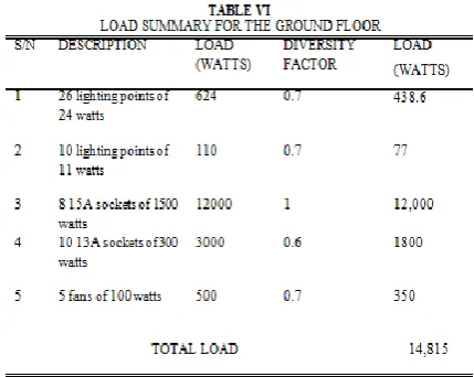
A. Load Description
At the completion of the design, it is discovered that the ground floor requires 36 lighting points, eight 15A sockets, ten 13A sockets and 5 fans. The first floor requires 20 lighting points, six 15A sockets, 6 fans and fifteen 13A sockets. This results in a total of 56 lighting points, fourteen 15A sockets, twenty-five 13A sockets and 11 fans.
The total estimated load demand for the ground floor is 14.8kW, while that of the first floor is 12.5kW. The total estimated load demand for the whole building is 27.3kW. For proper load scheduling, the recommended distribution board to be used for both floors is the 6-way, 30A T.P.N (Three phase and neutral) distribution board. The 60A Molded case circuit breaker (MCCB) is recommended for the design, to serve as over-current protection for the whole building.
For the alternative power supply source, a 34KVA generator is recommended to power the entire load in the building. A 5kW inverter is also recommended to power only the lighting points, fans and 13A sockets. In sizing the solar inverter to be used in the building; 21 solar panels of 435W, 72.9V are cascaded. This consists of 3 series strings of panels, with each string containing 7 panels connected in parallel. Also, the battery bank sizing resulted in cascading 8 batteries rated 12V, 530Ah. 4 strings are connected in series; each string contains 2 batteries connected on parallel.
B. Bill of Engineering Measurement and Evaluation (BEME)
The bill of engineering measurement and evaluation provided in Table X is a list of the quantity and cost of materials needed for the implementation of the design. It also includes the cost of labour and contingency cost.
From, the above analysis, the total cost for the whole design is estimated to be about N1, 130,000 only, which is about $3138.9 only.
V. CONCLUSION AND RECOMMENDATION
A. Conclusion
This paper strictly adheres to the governing rules and regulations of electrical services design. The design was carried out using the AutoCAD software from which the estimated total load drawn by the building was calculated to be 27.3kW. The total load was used to propose a 34kVA generator or a 5000kW inverter for the building. The key point of this design is the use of energy saving equipment and techniques in designing to consume far less energy compared to other designs of similar nature using other non-energy saving techniques. After preparing the bill of quantities, it is seen that the design is more expensive than its counterparts; this is because energy saving techniques requires a very high initial cost, but in the long run it is more economical than other techniques.
B. Recommendations
required calculation for any electrical installation directly from the drawings, and thus producing all the results, calculation sheets, bill of material and costs, and also the technical report as well as the final drawing (i.e. panel drawing, plan views, etc). This will surely simplify and eliminate error occurring by reading values directly from produced drawings. Also, home automation can be included in future designs such that appliances in the building can be controlled remotely using a smart phone.
REFERENCES
[1] M. Eric, “Efficient energy use”, Wikipedia [Online]. Available: http://en.m.wikipedia.org/wiki/efficient_energy_use. [Accessed 15 March 2018].
[2] N. Kaseke, S. Hosking, “Sub-Saharan African Electricity Supply Inadequacy: Implications”. East African Social Science research,
2013.
[3] B. Jones, “History of electrical design”, Modern electrical engineering blog, [Online]. Available: http://www.cim-team.com.br/modern- electrical-engineering-blog/recap-over-the-history-of-electrical-design. [Accessed 25 March 2018].
[4] C. Ejele, “Electrical services redesign of Alvan-Ikoku hostel in UNN using autocad”, unpublished final year project, the Department Of Electrical and Computer Engineering, Ahmadu Bello University, Zaria, 2015.
[5] M. A Adeshina, “A proposed one storey two bedroom twin flat residential building”, published final year project, Department Of Electrical Engineering, UNN, 2014.
[6] U. Eze, “Electrical services design of a two storey office building”, unpublished final year project, Department of Electrical Engineering, UNN, 2017.
[7] V. Sabrosa, “Cable sizes”, [Online]. Available: http://diydoctor.org.uk/projects/cablesizes.htm. [Accessed 4 April 2018].
[8] CSE, “Technical tables”, [Online]. Available: https://www.cse-distributors.co.uk/cable/technical-tables-useful-info/table-4e1a/. [Accessed 18 May 2018].
[9] “Electrical technology, how to find the suitable size of cable & wire”, [Online]. Available: http://www.electricaltechnology.org/2013/10/How-to-determine-the- suitable-size-of-cable-for-Electrical-Wiring-Installation-with-Solved-Examples-in-both-British-and-SI-System.html. [Accessed 2 May 2018].
[10] NOAO, “Recommended Light Levels”, New York.
[11] J.M Lahoria, S.L Uppal, “Elecrical Wiring Estimating and Costing”, India: Khanna publishers, 1987.
[12] W. Steward, A. Stubbs, “Modern Wiring Practice”, Oxford: B-H Newnes, 1995.
[13] “Wiring Methods”, [Online]. Available: http://www.electrical4u.com/system-of-wiring/. [Accessed 4 April 2018].